Smart Cover HHO EFIE User manual

Installation and Operation Manual

HEC Chip - Installation
guide
2
Contents
Disclaimer...........................................................................................................................3
Safety precautions.............................................................................................................3
Parts list..............................................................................................................................3
Installation..........................................................................................................................4
Locating the OBD-II Port..............................................................................................................4
Populated pins in the OBD-II Port...............................................................................................5
Protocol verification and wire connections..................................................................................5
Making the wire connections ........................................................................................................7
Calibration..........................................................................................................................7
Initial Calibration ..........................................................................................................................7
Recalibrating ..................................................................................................................................7
Resetting..........................................................................................................................................8
LED states...............................................................................................................................8
Stand-by Mode ...............................................................................................................................9
Power Mode....................................................................................................................................9
Calibration......................................................................................................................................9
HEC Chip - Installation
guide
3
Disclaimer
When purchasing this device, you are held responsible for any damage that may occur during
installation or operation of this device. The manufacturer or seller are not held liable and holds no
responsibility for any personal harm or property damage. Thank you for purchasing the HEC Chip -
Dynamic Soft-Flash Performance Chip. Please read the contents below carefully in order to
understand the installing and operation procedures before getting started.
Safety precautions
Read and follow these safety precautions to avoid hazards. If you do not understand these
instructions or do not like to work on vehicles, please have a qualified mechanic do the installation
for you. Incorrectly installing or using the HEC Chip and/or the HHO System may result in serious
damage to you and/or your vehicle. It should take approximately 20 minutes to install this device, so
ensure that you have enough time to complete the installation. Be sure to work outside and make
sure the engine is off. Be sure to wear goggles and rubber gloves and only use professional tools;
use common sense and general safety procedures used for any work carried out on automotive
installations and maintenance.
Parts list
The HEC Chip package includes the following items :
•1 Dynamic Soft-Flash Performance Chip with 4 wires for connection
•4 Red Scotchlock Terminals.
HEC Chip - Installation
guide
4
Installation
Thank you for purchasing the HHO EFIE Chip. Please take the time to read through this manual to
understand the installation and operation procedures before getting started. The Dynamic Soft-
Flash Performance/Fuel Chip is a new concept developed by the HHO Plus Team, and is not
offered anywhere else. It works by dynamically changing the values in the ECU. Each HEC Chip
comes pre-programmed with a set of EPROM addresses that directly affect efficiency and
performance. When the ECU attempts to read the specific EPROM address, the HEC Chip patches
the factory value with one from its on-board performance tuned map, allowing you to unleash your
engine's full potential.
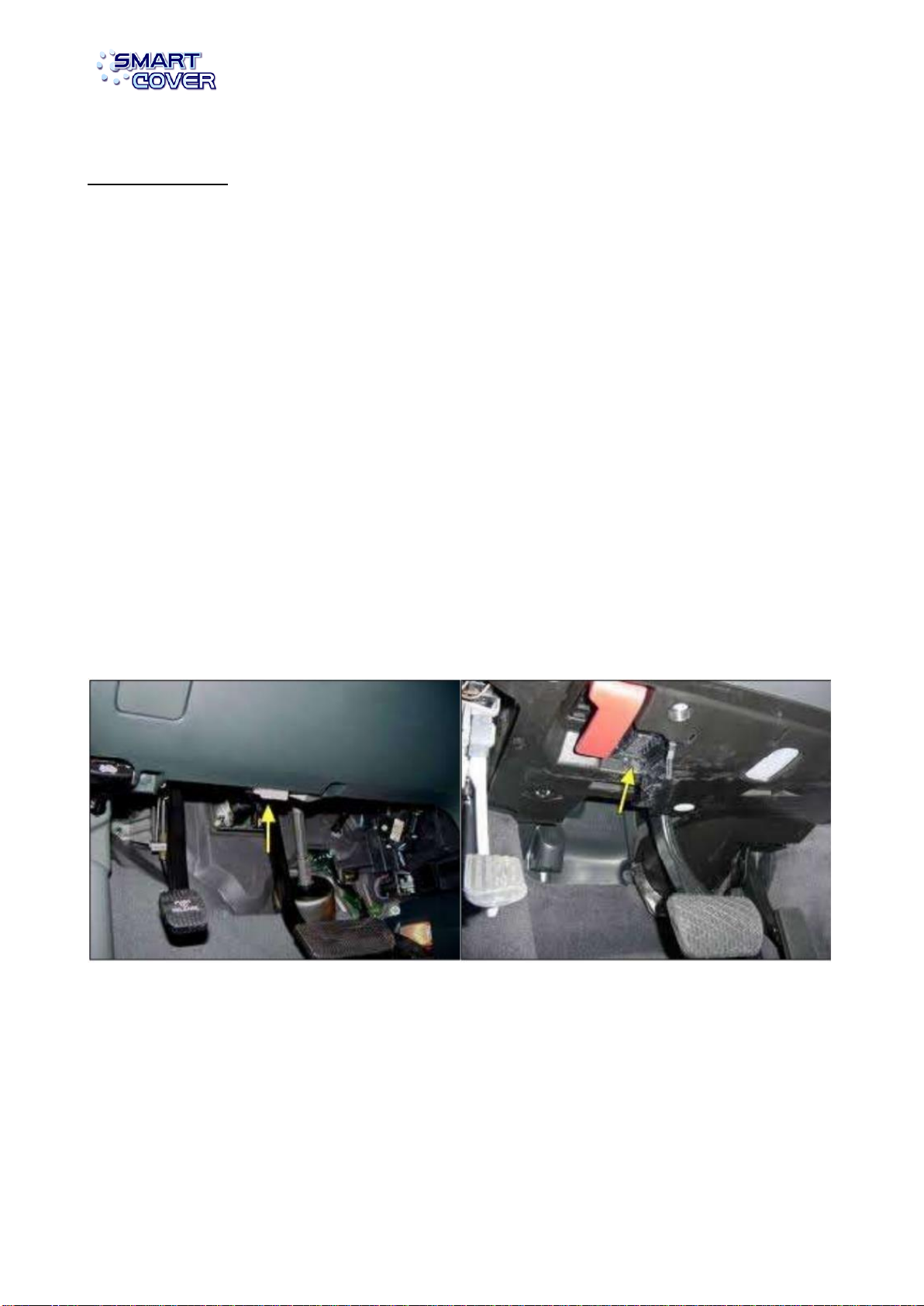
Locating the OBD-II Port
On-board diagnostics, or OBD, is an automotive term referring to a vehicle's self-diagnostic and
reporting capability. OBD systems give the vehicle owner or a repair technician access to state of
health information for various vehicle sub-systems. Start by locating your OBD II Port. If you don't
know where it is, go to http://www.obdclearinghouse.com/index.php?body=oemdb and enter
your year, make, and model. Normally the OBD II Port is located in the compartment located
underneath the steeringwheel:

HEC Chip - Installation
guide
5
Populated pins in the OBD-II Port
The OBD-II Port has 16 pins arranged in a numerical order. Please refer to the illustrations below
for typical configuration of the OBD-II pins according to the position of the port in the car:
As you can verify the numeration is exactly the same whatever is the position of the port. Use a
paper to write down the pin numbers populated in the OBD-II port. Look at the examplebelow:
The populated pins are: 1, 4, 5, 7, 11, 13 and 16 If you are not sure, take out the OBD-II port and
check the wires connected on the back.
Protocol verification and wire connections
The 4 wires of the HEC Chip will connect to the wires on the back of the OBD-II port. The Red wire
will always connect to the wire coming from pin 16 (+12V Power) and the Black wire will always
connect to the wire coming from pin 4 (Ground). The Green and White wires will be connected
according to the protocol in your car:
PWM - If pins 2 and 10 are populated, then connect White to pin 2, and Green to pin 10.
VPW - If pin 2, but not pin 10 is populated, then connect White to pin 2, and Green to pin 5.
ISO - If pin 7 is populated, then connect White to pin 7. Connect Green to pin 15 if populated or pin
5 if not.
CAN - If pins 6 and 14 are populated, then connect White to pin 6, and Green to pin 14.

HEC Chip - Installation
guide
6

HEC Chip - Installation
guide
7
Making the wire connections
Open the blue box and use the Red Scotchlocks Terminals to make the wire connections to the
cables, in the back of the OBD-II port, coming from the pins selected according to the protocol in
your car.
Calibration
Initial Calibration
After installing for the first time, start the car's engine. The HEC Chip will determine which protocol
you have and calibrate its on-board map and communication baud rates. This calibration should
take around 1-3 minutes, depending on the vehicle. During calibration the LINK LED will flash
rapidly. Once the LINK LED becomes solid green, then calibration is complete. Do not drive
or accelerate the engine during calibration. Allow engine to idle until calibration complete. In
addition to calibration, most vehicles will require around 150 kms adjustment period for maximum
gains.
Recalibrating
In the event you make any changes to your vehicle you must reset the Chip for optimum gains. If
you feel the chip is no longer functioning properly, a reset will return it to normal. Changes include
anything that affects engine performance or efficiency, such as new engine components, or
replacing defectiveparts.

HEC Chip - Installation
guide
8
Resetting
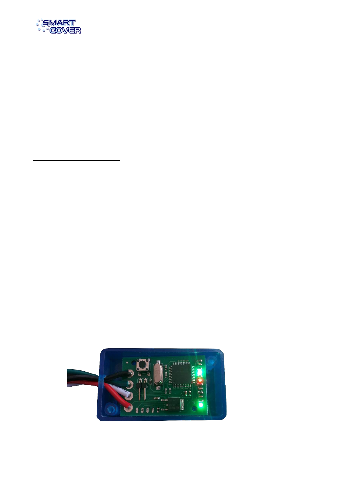
Turn the vehicle off. Open the blue case and press button inside the chip. Both LEDs will come on,
then the RED LED may flash up to 20 times, then the Chip will enter Standby Mode. The Chip will
now recalibrate the next time the vehicle is started.
Reset Button
LEDstates
The HEC Chip has 3 information LEDs. They will provide you all the information necessary
regarding the performance of the chip.

HEC Chip - Installation
guide
9
Stand-by Mode
STBY LED blinks every 5-10 seconds. There is no signal from the car’s computer. The device may
not enter stand-by on some cars in which the ECU remains active after engine shut-off. This is
normal and will not adversely affect operation.
Power Mode
PWR and LINK LEDs are solid green. This indicates the device is
connected and functioning properly.
Calibration
PWR LED is solid Green. Link LED is flashing. ECU LED is solid or
flashing. The device is in AutoCalibration mode. During this time, your
engine will begin evaluation to generate an offset map. This allows
the device to tune better the car for optimum performance.

Table of contents
Popular Computer Hardware manuals by other brands


Oracle
Oracle 1.6TB NVMe SSD user guide

D-Link
D-Link Express EtherNetwork DFE-670TXD Specifications

AudioSource
AudioSource SS Five owner's manual

NXP Semiconductors
NXP Semiconductors NavQPlus 8MPNAVQ-8G-G quick start guide

Cincoze
Cincoze DC-1000 user manual

Ashly
Ashly Keyboard Input Processor SC-44 operating instructions