Smart Dedicated Design STR7202 User manual

Installation Manual STR7202 TAG3 & SFM7704 TAG1
DBCI-0512-0052-V008
STR7202 2-Side Trimmer & SFM7704 Square Fold Module
V008
RI01
13-09-2012
DBCI-0512-0052-V008
1 - 48
2-SIDE TRIMMER STR7202
&
SQUARE FOLD MODULE SFM7704
INSTALLATION MANUAL

Installation Manual STR7202 TAG3 & SFM7704 TAG1
DBCI-0512-0052-V008
STR7202 2-Side Trimmer & SFM7704 Square Fold Module
V008
RI01
13-09-2012
DBCI-0512-0052-V008
2 - 48
About this manual
Machines have much in common but there are differences because they can be mirrored, have different
colours or additional options. Therefore the machine on the pictures in this manual may be different.
This machine must be installed by a qualified technician.

Installation Manual STR7202 TAG3 & SFM7704 TAG1
DBCI-0512-0052-V008
STR7202 2-Side Trimmer & SFM7704 Square Fold Module
V008
RI01
13-09-2012
DBCI-0512-0052-V008
3 - 48
Contents
TITLE PAGE
ABOUT THIS MANUAL.................................................................................................................................... 2
CONTENTS....................................................................................................................................................... 3
1. SAFETY.................................................................................................................................................. 4
2. GENERAL .............................................................................................................................................. 5
3. BASIC INFORMATION .......................................................................................................................... 6
4. INSTALLATION...................................................................................................................................... 7
4.1 REQUIREMENTS.......................................................................................................................................... 7
4.1.1 Tools.................................................................................................................................................. 7
4.1.2 Parts (Supplied)................................................................................................................................. 7
4.2 PREPARING CANON BOOKLET TRIMMER C1 &D1 ........................................................................................ 8
4.3 PREPARING THE STR ............................................................................................................................... 10
4.4 PREPARING THE SFM............................................................................................................................... 13
4.5 PREPARING THE BELT STACKER................................................................................................................ 14
4.6 MECHANICAL INSTALLATION ...................................................................................................................... 15
4.6.1 STR behind Canon Booklet Trimmer C1/D1................................................................................... 15
4.6.2 SFM behind STR............................................................................................................................. 19
4.6.3. Belt Stacker on STR....................................................................................................................... 21
4.6.4. Belt Stacker on SFM ...................................................................................................................... 22
4.7 ELECTRICAL INSTALLATION........................................................................................................................ 23
4.7.1 Tapping STR Transformer............................................................................................................... 23
4.7.2 Tapping SFM Transformer .............................................................................................................. 24
4.7.3 Connecting STR to Canon Booklet Trimmer C1............................................................................. 25
4.7.4 Installing Start/Stop Interface in Canon Booklet Trimmer D1 ......................................................... 26
4.7.5 Connecting STR to Canon Booklet Trimmer D1............................................................................. 30
4.7.6 Connecting SFM to STR ................................................................................................................. 31
4.7.7 Connecting Belt Stacker to STR...................................................................................................... 33
4.7.8 Connecting Belt Stacker to SFM..................................................................................................... 34
4.8 SECURING CABLES IN STR &SFM............................................................................................................ 35
4.9 FINALIZING INSTALLATION.......................................................................................................................... 36
4.9.1 With Canon Booklet Trimmer C1..................................................................................................... 36
4.9.2 With Canon Booklet Trimmer D1..................................................................................................... 37
4.9.3 Belt Stacker Outfeed Cover setting................................................................................................. 38
4.9.4 STR on External Power................................................................................................................... 39
5. SYSTEM SETUP.................................................................................................................................. 40
5.1 SYSTEM SETUP ........................................................................................................................................ 40
5.2 LANGUAGE............................................................................................................................................... 41
5.3 THICKNESS DETECTION SETUP ................................................................................................................. 42
6. JOB TESTING...................................................................................................................................... 44
7. TECHNICAL INFORMATION............................................................................................................... 45
7.1 STR7202 2-SIDE TRIMMER ...................................................................................................................... 45
7.2 SFM7704 SQUARE FOLD MODULE............................................................................................................ 47

Installation Manual STR7202 TAG3 & SFM7704 TAG1
DBCI-0512-0052-V008
STR7202 2-Side Trimmer & SFM7704 Square Fold Module
V008
RI01
13-09-2012
DBCI-0512-0052-V008
4 - 48
1. Safety
Contents
Carefully read the Safety Instruction Document (DBCH-0512-0000-V000) before installing,
operating or servicing your equipment.

Installation Manual STR7202 TAG3 & SFM7704 TAG1
DBCI-0512-0052-V008
STR7202 2-Side Trimmer & SFM7704 Square Fold Module
V008
RI01
13-09-2012
DBCI-0512-0052-V008
5 - 48
2. General
Contents
With the addition of the 2-Side Trimmer STR to the SDD product range, a cost effective full-bleed solution is
available which has a small footprint and is easily to operate. This machine is designed with high reliability in
mind resulting in cost effective operation due to long production with minimal service requirements.
The 2-Side Trimmer, further referred to as STR, is used for trimming the bleed off a booklet. Booklets with a
maximum thickness of 5 mm can be trimmed from 2mm to 35mm on each short edge of the booklet, to a
minimum of 200mm and a maximum of 320mm finished size. It is also possible to trim asymmetrical.
Operating the STR and adjusting the trim settings is achieved via the User Interface (UI) on the STR.
In the schedule below some results are shown which are possible with the STR by using a different Centre
Offset (symmetrical or asymmetrical):
Centre Offset:
15mm
Centre Offset:
-15mm
Centre Offset:
0mm
33,5mm Waste
33,5mm Waste
3,5mm Waste
18,5mm Waste
3,5mm Waste
Finished Size:
260.0mm
Infeed Size:
297.0mm
18,5mm Waste

Installation Manual STR7202 TAG3 & SFM7704 TAG1
DBCI-0512-0052-V008
STR7202 2-Side Trimmer & SFM7704 Square Fold Module
V008
RI01
13-09-2012
DBCI-0512-0052-V008
6 - 48
3. Basic information
Contents
Study the picture below to become familiar with the main components.
Orientation is based on the paper flow direction.
No.
Description
1.
Top Cover STR
2.
Trim Waste Bin
3.
Operator Side (Left)
4.
User Interface (UI)
5.
Power switch (inside)
6.
Top Cover SFM7704
7.
Square Fold Module SFM7704 (Option)
8.
Belt Stacker
Front
Rear
Left
Right
Top
2
5
Bottom
8
1
3
4
6
7

Installation Manual STR7202 TAG3 & SFM7704 TAG1
DBCI-0512-0052-V008
STR7202 2-Side Trimmer & SFM7704 Square Fold Module
V008
RI01
13-09-2012
DBCI-0512-0052-V008
7 - 48
4. Installation
Contents
4.1 Requirements
4.1.1 Tools
Description
Wrench 7mm
Wrench 24mm
Allen key 5mm
Cutting plier
Screwdriver PZ1
Software Loading Cable
4.1.2 Parts (Supplied)
Description
Qty
Tie wrap 16cm (small)
10
Label Disconnects only BLT7202 230VAC 50Hz
1
Label Disconnects only BLT7202 120VAC 60Hz
1
Label Disconnects only SFM7704 230VAC 50Hz
1
Label Disconnects only SFM7704 120VAC 60Hz
1
Taptite hex flange screw M4x8
2
Washer M4 (Toothed)
2
Additional Interface Cable for Canon Booklet Trimmer C1
1
Start/Stop Interface Cable for Canon Booklet Trimmer D1
1
Power Cord EU
1
Power Cord US
1
Power Cord GB
1

Installation Manual STR7202 TAG3 & SFM7704 TAG1
DBCI-0512-0052-V008
STR7202 2-Side Trimmer & SFM7704 Square Fold Module
V008
RI01
13-09-2012
DBCI-0512-0052-V008
8 - 48
4. Installation (continued)
Contents
4.2 Preparing Canon Booklet Trimmer C1 & D1
Fig. 4.2.1 Fig. 4.2.2
Fig. 4.2.3 Fig. 4.2.4
Step
Action
Remarks
1.
Disconnect Canon Belt Stacker.
Disconnect Belt Stacker from Booklet Trimmer[A] (Fig.
4.2.1).
2.
Remove Canon Belt Stacker.
Remove bolts [B] on both sides (Fig. 4.2.2), lift off Belt
Stacker and set unit aside.
3.
Remove two Booklet Guides [C].
(Fig. 4.2.3).
4.
Remove Sensor Reflection Plate
[D].
Remove from inside (Fig. 4.2.3 & 4.2.4).
C
D
D
B
A

Installation Manual STR7202 TAG3 & SFM7704 TAG1
DBCI-0512-0052-V008
STR7202 2-Side Trimmer & SFM7704 Square Fold Module
V008
RI01
13-09-2012
DBCI-0512-0052-V008
9 - 48
4. Installation (continued)
Contents
4.2 Preparing Canon Booklet Trimmer C1 & D1 (continued)
Fig. 4.2.5
Step
Action
Remarks
5.
Remove two Plastic Bolts [E].
(Fig. 4.2.5)
E
Installation Manual STR7202 TAG3 & SFM7704 TAG1
DBCI-0512-0052-V008
STR7202 2-Side Trimmer & SFM7704 Square Fold Module
V008
RI01
13-09-2012
DBCI-0512-0052-V008
10 - 48
4. Installation (continued)
Contents
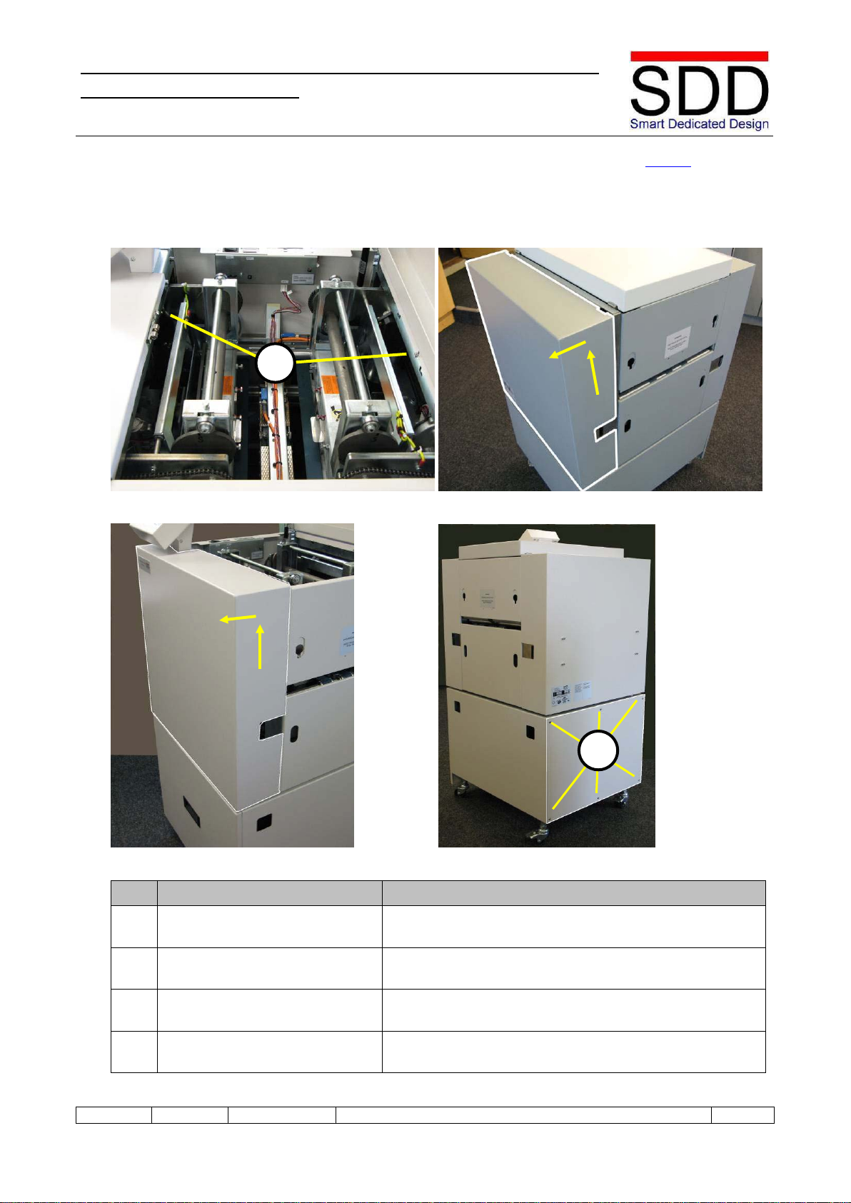
4.3 Preparing the STR
Fig. 4.3.1 Fig. 4.3.2
Fig. 4.3.3 Fig. 4.3.4
Step
Action
Remarks
1.
Loosen Upper Covers.
Open Top Cover, loosen Hex Bolts [A] and close Top
Cover (Fig. 4.3.1).
2. Remove Upper Right Cover. Slightly lift Right Cover, disconnect grounding wire and
remove Cover (Fig. 4.3.2).
3. Remove Upper Left Cover. Slightly lift User Interface and Left Cover, disconnect
grounding wire and remove Cover (Fig. 4.3.3).
4.
Remove Lower Right Cover.
Loosen and remove 6x M4 Hexagon bolts [B] and remove
Cover (Fig. 4.3.4).
B
A

Installation Manual STR7202 TAG3 & SFM7704 TAG1
DBCI-0512-0052-V008
STR7202 2-Side Trimmer & SFM7704 Square Fold Module
V008
RI01
13-09-2012
DBCI-0512-0052-V008
11 - 48
4. Installation (continued)
Contents
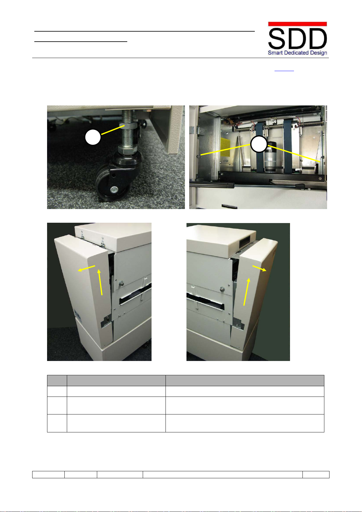
4.3 Preparing the STR (continued)
Fig. 4.3.5 Fig. 4.3.6
Fig. 4.3.7
Step
Action
Remarks
3.
Loosen Upper Nuts.
Loosen nut [C] on the left and right front wheel (Fig. 4.3.5
& 4.3.6).
4.
Adjust STR Infeed Height.
Adjust STR Infeed Height by turning wheelnut [D] on both
front wheels (Fig. 4.3.5 & 4.3.6).
5.
Set STR Height
Initially set height to approximately 86 cm (Fig. 4.3.7).
D
C
≈86cm
Installation Manual STR7202 TAG3 & SFM7704 TAG1
DBCI-0512-0052-V008
STR7202 2-Side Trimmer & SFM7704 Square Fold Module
V008
RI01
13-09-2012
DBCI-0512-0052-V008
12 - 48
4. Installation (continued)
Contents
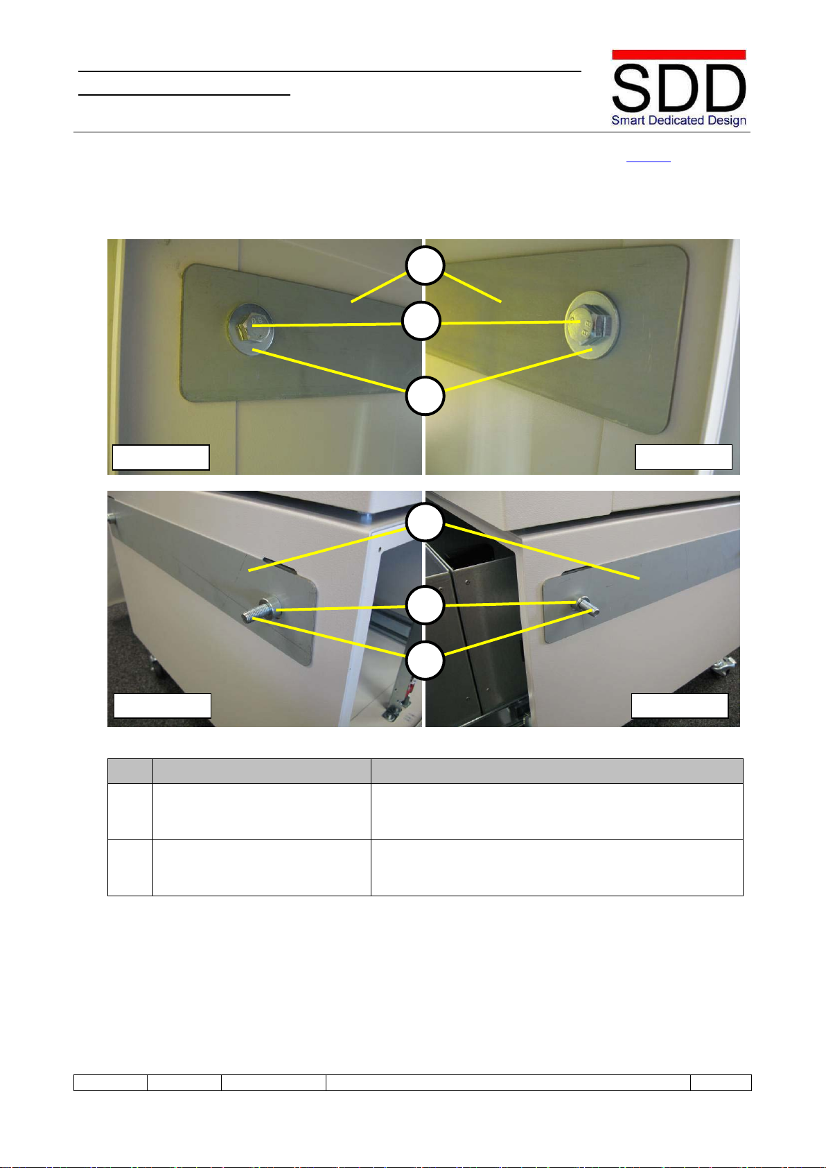
4.3 Preparing the STR (continued)
Fig. 4.3.8 Fig. 4.3.9
Fig. 4.3.10 Fig. 4.3.11
Step
Action
Remarks
6.
Mount Inside Connection Plate.
At the Infeed Side open Waste Bin and mount Inside
Connection Plate by placing Bolt [F] with washer [G]
through Connection Plate [E] (Fig. 4.3.8 & 4.3.9).
7. Mount Outside Connection
Plate. At the Outfeed Side mount Connection Plate [H] by
placing it with washers [I] over Bolts [F] (Fig. 4.3.10 &
4.3.11).
Inside - left
Inside - right
Outside - right
Outside - left
E
G
F
I
H
F
Installation Manual STR7202 TAG3 & SFM7704 TAG1
DBCI-0512-0052-V008
STR7202 2-Side Trimmer & SFM7704 Square Fold Module
V008
RI01
13-09-2012
DBCI-0512-0052-V008
13 - 48
4. Installation (continued)
Contents
4.4 Preparing the SFM
Fig. 4.4.1 Fig. 4.4.2
Fig. 4.4.3 Fig. 4.4.4
Step
Action
Remarks
1.
Loosen Upper Nuts
Loosen Upper Nuts [B] of all wheel bolts (Fig. 4.4.1).
2. Loosen Covers Open Top Cover and loosen bolts [B] but do not remove
them (Fig. 4.4.2).
3.
Remove Covers
Lift the Covers slightly up, swing from the top outward
and remove both from the machine (Fig. 4.4.3 & 4.4.4).
A
B
Installation Manual STR7202 TAG3 & SFM7704 TAG1
DBCI-0512-0052-V008
STR7202 2-Side Trimmer & SFM7704 Square Fold Module
V008
RI01
13-09-2012
DBCI-0512-0052-V008
14 - 48
4. Installation (continued)
Contents
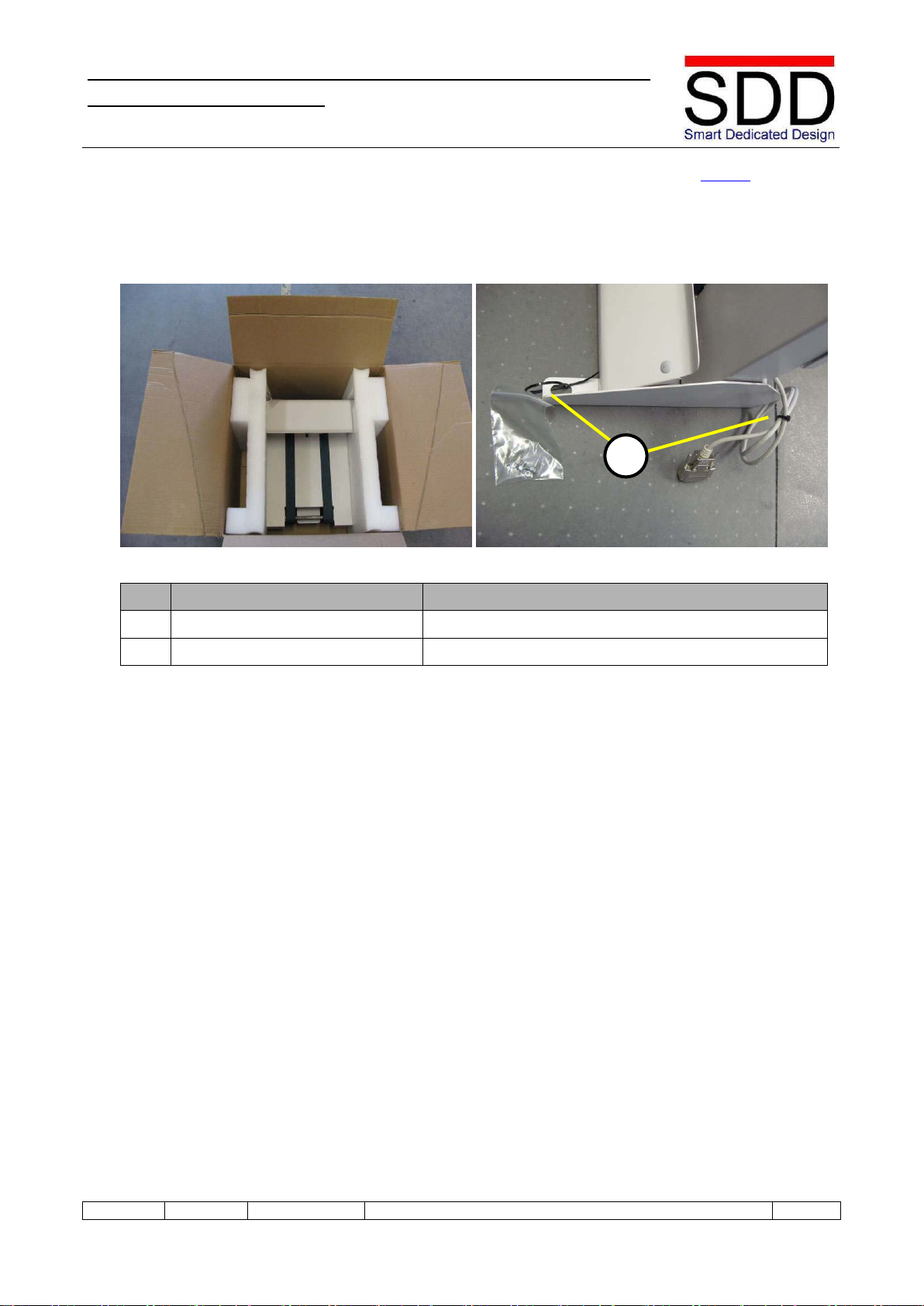
4.5 Preparing the Belt Stacker
Fig. 4.5.1 Fig. 4.5.2
Step
Action
Remarks
1.
Unpacking Belt Stacker
(Fig. 4.5.1)
2.
Remove tiewraps
Remove the tiewraps (A) with a cutting plier. (Fig. 4.5.2)
A

Installation Manual STR7202 TAG3 & SFM7704 TAG1
DBCI-0512-0052-V008
STR7202 2-Side Trimmer & SFM7704 Square Fold Module
V008
RI01
13-09-2012
DBCI-0512-0052-V008
15 - 48
4. Installation (continued)
Contents
4.6 Mechanical Installation
4.6.1 STR behind Canon Booklet Trimmer C1/D1
Fig. 4.6.1
Fig. 4.6.2
Step
Action
Remarks
1. Positioning STR. Position STR behind Canon Booklet Trimmer (Fig. 4.6.1)
and align units as per following steps.
2. Horizontal alignment Horizontally align the lower edge of the STR Infeed slot
on the lower edge of the Canon Booklet Trimmer Outfeed
slot (Fig. 4.6.2).
3.
Adjust STR height.
If necessary adjust STR height as per 4.3 Preparing STR
STR
C1/D1

Installation Manual STR7202 TAG3 & SFM7704 TAG1
DBCI-0512-0052-V008
STR7202 2-Side Trimmer & SFM7704 Square Fold Module
V008
RI01
13-09-2012
DBCI-0512-0052-V008
16 - 48
4. Installation (continued)
Contents
4.6 Mechanical Installation (continued)
4.6.1 STR behind Canon Booklet Trimmer C1/D1 (continued)
Fig. 4.6.3 Fig. 4.6.4
Fig. 4.6.5
Step
Action
Remarks
4.
Vertical alignment
Vertically center align the STR Infeed slot and Canon
Booklet Trimmer Outfeed slot.
=
=
=
=

Installation Manual STR7202 TAG3 & SFM7704 TAG1
DBCI-0512-0052-V008
STR7202 2-Side Trimmer & SFM7704 Square Fold Module
V008
RI01
13-09-2012
DBCI-0512-0052-V008
17 - 48
4. Installation (continued)
Contents
4.6 Mechanical Installation (continued)
4.6.1 STR behind Canon Booklet Trimmer C1/D1 (continued)
Fig. 4.6.6 Fig. 4.6.7
Fig. 4.6.8 Fig. 4.6.9
Step
Action
Remarks
5.
Align Booklet Guide.
Booklet Guide [A] (Fig. 4.6.6) should not touch STR
Upper Infeed Roller [B] (Fig. 4.6.7) but be 2 to 5 mm
below the roller (Fig. 4.6.8. & 4.6.9).
6.
Adjust STR height.
If necessary adjust STR height as per 4.3 Preparing STR
A
B
A
B
A

Installation Manual STR7202 TAG3 & SFM7704 TAG1
DBCI-0512-0052-V008
STR7202 2-Side Trimmer & SFM7704 Square Fold Module
V008
RI01
13-09-2012
DBCI-0512-0052-V008
18 - 48
4. Installation (continued)
Contents
4.6 Mechanical Installation (continued)
4.6.1 STR behind Canon Booklet Trimmer C1/D1 (continued)
Fig. 4.6.10 Fig. 4.6.11
Fig. 4.6.12 Fig. 4.6.13
Step
Action
Remarks
7. Connect Units Open Waste Bin and connect STR to Canon Finisher by
gently fastening Bolts [C] two or three turns (Fig. 4.6.10).
8.
Check Height.
Check Booklet Guide position and that STR is level left to
right. If necessary adjust STR height with bolts [E] as per
4.3 Preparing STR.
9.
Level STR.
Check that STR is level front to rear. If necessary adjust
STR height taking care not to change height on front.
10.
Set Height.
Tighten the Upper nuts [D] (Fig. 4.6.13) to set height.
C
E
D

Installation Manual STR7202 TAG3 & SFM7704 TAG1
DBCI-0512-0052-V008
STR7202 2-Side Trimmer & SFM7704 Square Fold Module
V008
RI01
13-09-2012
DBCI-0512-0052-V008
19 - 48
4. Installation (continued)
Contents
4.6 Mechanical Installation (continued)
4.6.2 SFM behind STR
Fig. 4.6.14 Fig. 4.6.15
Fig. 4.6.16 Fig. 4.6.17
Step
Action
Remarks
1.
Positioning SFM
Open the SFM Top cover and lower the Locking Bracket [A]
by loosening Hex Nuts [B] (Fig. 4.6.15) and position the SFM
behind the STR (Fig. 4.6.14).
2.
Adjust height SFM
Adjust the height of the SFM by turning all wheel bolts [C]
(Fig. 4.6.16).
3.
Check Fitting
Make sure the Positioning Studs [D] of the STR fit in the
Locking Bracket of the SFM (Fig. 4.6.17).
C
D
B
A

Installation Manual STR7202 TAG3 & SFM7704 TAG1
DBCI-0512-0052-V008
STR7202 2-Side Trimmer & SFM7704 Square Fold Module
V008
RI01
13-09-2012
DBCI-0512-0052-V008
20 - 48
4. Installation (continued)
Contents
4.6 Mechanical Installation (continued)
4.6.2. SFM behind STR (continued)
Fig. 4.6.18 Fig. 4.6.19
Step
Action
Remarks
4. Check height SFM. The top cover of the SFM is at the same height as the STR
and both units are level (Fig. 4.6.18)
5.
Setting the SFM parallel to
the STR.
Make sure that the SFM is parallel to the STR. If necessary,
adjust the SFM by turning nuts (C) on the outfeed side wheels
of the SFM (Fig. 4.6.18 & 4.6.19).
6. Tighten Upper Nuts When the height of the SFM is correct, tighten the Upper Nuts
[E] (Fig. 4.6.19).
E
C
Other manuals for STR7202
1
This manual suits for next models
1
Table of contents
Popular Trimmer manuals by other brands


Havener Enterprises
Havener Enterprises e40 Parts and owners manual

Makita
Makita DUR368A instruction manual

Gardener's Choice
Gardener's Choice GCT-260 user manual

Worx
Worx WG286E Safety and operating manual

Husqvarna
Husqvarna 233RJ Operator's manual

Craftsman
Craftsman WEEDWACKER 358.799250 Operator's manual


