SmartBridges airPoint XO2 User manual

airPoint XO™Series
Wireless Access Points
Quick Install Guide

airPoint XO Series Page 2 of 24
Professional Installation
airPoint XO and airPoint XO2 require installation by professional installer.
Steps:
• Choose the antenna from the antennas certified with airPoint XO /
airPoint XO2
• The RF cable should be of 1 meter length, LMR 400 cable with
N male connectors at both ends.
• Set the power output of airPoint XO / airPoint XO2 using the
procedure shown in "Configuring airPoint XO" / “ Configuring
airPoint XO2 “. The RF output power can be adjusted to a
maximum of +17dBm.
• Keep safe distance of 32 centimeters away from the antenna.
• Professional installation is required for all antennae.
RF Safety Precaution
airPoint XO , airPoint XO2 gives out electromagnetic Radiation
through the antenna . . It is harmful to be in contact with the
antenna or to be in close proximity when the airPoint XO or
airPointXO2 when it is powered ON . The safe distance is 45
centimeters from the antenna . The indication for RF radiation is the
lighting up of Blue LED on the device .

airPoint XO Series Page 3 of 24
Table of Contents
1. airPoint XO™ Series.................................................................. 4
2. Package Contents ..................................................................... 6
3. Hardware Installation................................................................. 6
4. Installing the airPoint XO™ Series ............................................ 8
4.1 Pole Mounting...................................................................... 9
4.2 Mounting the Antenna........................................................ 10
4.3 Cabling............................................................................... 11
4.4 LEDs Status....................................................................... 12
4.5 Protection........................................................................... 12
5. Service and Support ................................................................ 13
6. Frequently Asked Questions.................................................... 14
Appendix A – Specifications ........................................................ 16
Appendix B –Warranty, License and Copyrights ......................... 18
Appendix C -Declaration of Conformity ....................................... 19

airPoint XO Series Page 4 of 24
1. airPoint XO™ Series
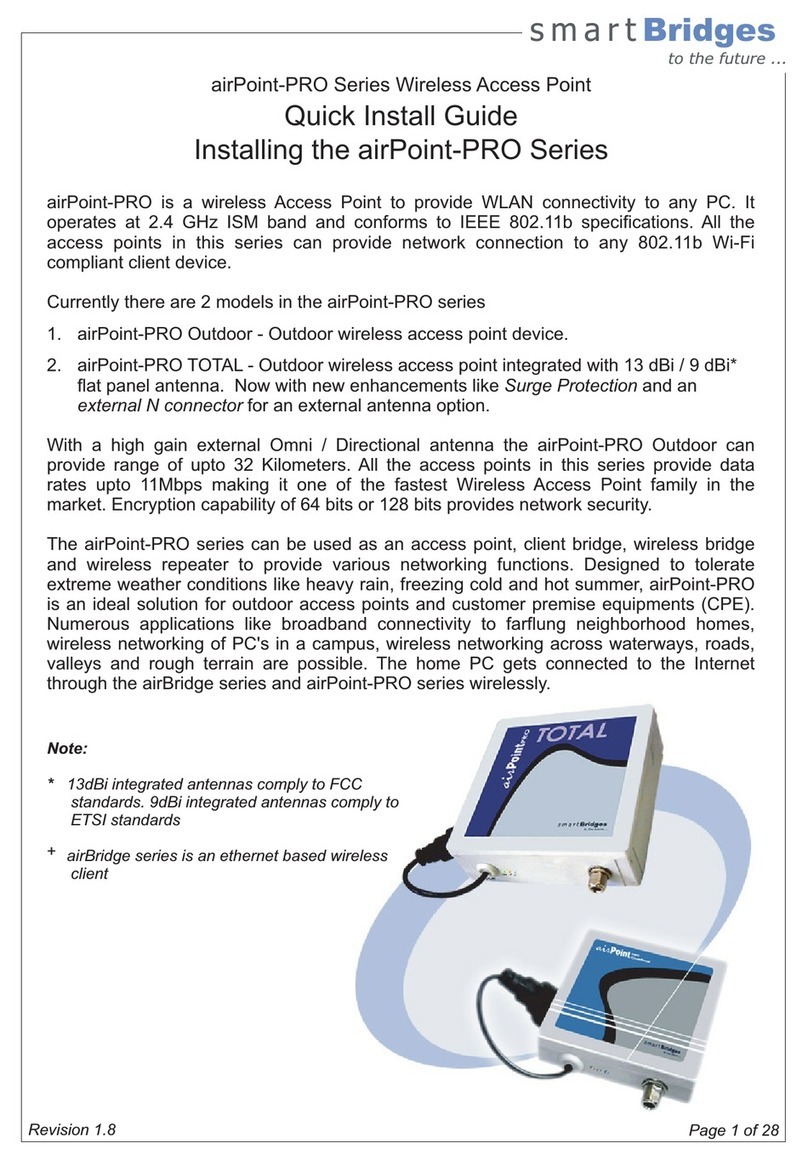
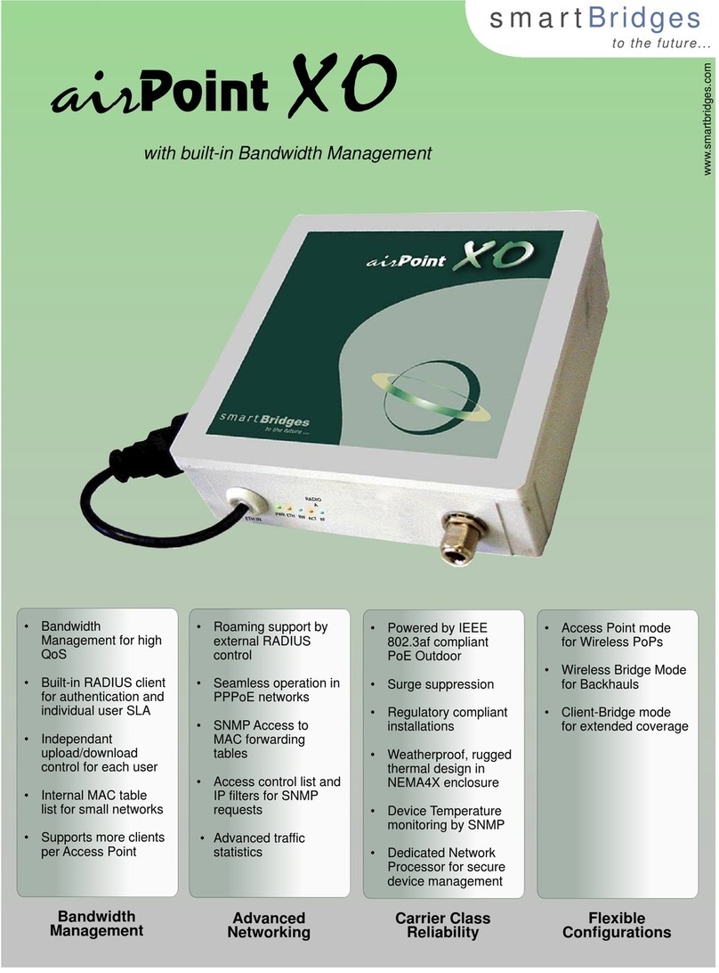
The smartBridges airPoint XO™ products are LongRange™, IEEE
802.11b compliant Access Point devices for deployment of Wireless Wide
Area Networks (WWANs). The airPoint XO™ products deal with four key
areas that are of vital importance in any WWAN network: Subscriber
Bandwidth Management, Advanced Networking Capabilities, Remote
Infrastructure Management and, Carrier-Class Reliability.
Currently there are 2 models in the airPoint XO™ series
1. airPoint XO™ - Outdoor wireless
access point with Bandwidth
Management
2. airPoint XO2™ - Dual radio outdoor
wireless access point with Bandwidth
Management
With a suitable external Directional antenna
the airPoint XO™ series can provide range of up to 32 Kilometers. All the
access points in this series provide data rates up to 11Mbps making it one
of the fastest Wireless Access Point family in the market. Encryption
capability of 64 bits or 128 bits provides network security.
The airPoint XO™ series can be used as an access point, client bridge,
wireless bridge and wireless repeater to provide various networking
functions. The dual radio XO2™ can be configured to work in Full
Repeater mode, Dual Access Point mode, Cell Extender mode and High
Reliability Access Point mode. Designed to tolerate extreme weather
conditions, the airPoint XO™ series provides a two-layered protection,
through the IEEE 802.3af compliant, PoE Outdoor™ (Power over
Ethernet) accessory for regulatory compliant installations. The radios are
supported by multiple Network Processing Elements to handle heavy
network loads. These devices can be remotely configured, monitored
upgraded, reset and even power cycled, thus allowing ease of
maintenance. Numerous applications like broadband connectivity to far
flung neighborhood homes, wireless networking of PC's in a campus,
wireless networking across waterways, roads, valleys and rough terrain
are possible. The home PC gets connected to the Internet through the

airPoint XO Series Page 5 of 24
airBridge series (Client devices) and the airPoint XO™ series (access
points) wirelessly.
Application Diagram for airPoint XO™
airPoint
XO
Access Point with Bandwidth Management
Client
Client
Client
Client
Client
Client
Internet
Backbone NOC
airPoint XO
Bandwidth limit of
512 kbps
Bandwidth limit of
128 kbps
Bandwidth limit of
256 kbps
Bandwidth limit of
128 kbps
Bandwidth limit of
512 kbps
Bandwidth limit of
1 Mbps
airPoint XO
Internet
Backbone
Network Management
Traffic

Backhaul
Connectivity
NOC
Internet
Backbone
airPoint
XO2
in Full Repeater mode
airPoint XO2
Client
Client
Client
airPoint XO Series Page 6 of 24
Application Diagram for airPoint XO2™
2. Package Contents
lairPoint XO™ or XO2™ Unit
l Power over Ethernet (PoE) Outdoor™, with 48 V power adapter and
Wall Plate Unit (standard accessories provided with airPoint XO™ series)
l Grounding Tag
l Pole Mounting Kit : U Bracket, Nuts, Washers
l Wall Mounting Kit : Wall plugs , Screws
l airPoint XO™ Setup Software and User Manual CD
l Quick Install Guide

airPoint XO Series Page 7 of 24
3. Hardware Installation
For airPoint XO™ and airPoint XO2™
•Connect an outdoor rated shielded Ethernet CAT 5 / 5e cable to
the RJ45 connector of the airPoint XO™ ( Located inside the
weather proof connector ) to the ETH OUT of PoE Outdoor™
(Refer to the PoE Outdoor™ user guide for detailed instructions)
•Connect the ETH IN RJ45 connector of the PoE Outdoor™ to the
ETH Out of the Wall Plate Unit with proper CAT 5 / 5e cable .
•Connect the ETH in of the Wall plate to the LAN port of the
PC or network through CAT 5 / 5e cable
•Connect the DC output ( RJ 11 Plug ) of the AC adapter to the
PWR in of the Wall plate unit
•Confirm that the AC input to the AC adaptor is 110V AC (+/-5%),
60Hz in US and 240V AC (+/-5%), 50 HZ in EU. Make sure the AC
input is clean of any surges or spikes. It is recommended to use a
use a Spike and a surge suppressor, buster or a UPS to make sure
that the power supply is clean. The UPS or buster should be of the
correct voltage and current rating. Make sure that the AC supply
has a proper Ground available to the surge suppressor, spike
protector or UPS.
•Use only smartBridges Power over Ethernet Outdoor™ with a 48V
AC adaptor.
•The specification for smartBridges AC adaptor :
Current Ratings 570 mA @ 48V
Type of Plug RJ 11 4p4c
Plug Polarity Pins 1, 2 Positive
Pins 3, 4 Negative
AC Input 90 ~ 267 V AC 40 ~ 60 Hz
•Connect the AC Adapter to the mains outlet.

airPoint XO Series Page 8 of 24
•Verify that the PWR , ETH and RF LEDs are ON .
•airPoint XO™ with its Factory Default Settings will serve the nearby
wireless clients
4. Installing the airPoint XO™ Series
Grounding :
•Crimp an AWG # 10 grounding wire to the Tag provided.
•Place this Tag on the grounding Stud at the bottom side of
the aP XO™ .
•Fasten it with the M6 nut tightly to the grounding Stud .
•Connect the other end of the earth wire to the Power Ground
on the premises .
Note : Grounding has to be done before mounting the aPXO™ on
the wall or pole .

airPoint XO Series Page 9 of 24
4.1 Pole Mounting

airPoint XO Series Page 10 of 24
Select the most appropriate place on the roof which will provide a direct
view to the Access Point. Secure a 1.5 inch steel pipe vertically and insure
that it cannot come off with wind force. Attach the bracket of the airPoint
XO™ or XO2™ unit with the 2pcs of U bolts to the pipe. Make sure to
tighten both top and bottom mounting plates to the pipe with U bolts, nuts
and spring washers. Tighten the nuts so that the bracket does not rotate
on the pipe. The mounting should be such that the antenna socket, LED's,
Ethernet cable outlet face downward.
Note:
1. Do not mount the unit upside down with RF connectors facing up.
2. There are no user adjustable parts inside and it is recommended
that the unit is used in the same way it is shipped.
3. Make sure that the unit is mechanically well secured to the
mounting tower, pole, mast or wall.
4. Radio communications requires Radio Line of Sight (RLOS) or
Visual Line of Sight. Therefore, it is essential that the antennas
connected to the airPoint XO™ or XO2™ and the Access Point
Clients, are in line of sight without any obstruction.
4.2 Mounting the Antenna
Antenna should be mounted on the same pipe as the airPoint XO™ or
XO2™and positioned above it. The height of the antenna and direction
should be in the direction of the Client devices. The antenna socket of the
airPoint XO™ or XO2™ and the antenna input have to be connected by an
RG 8 N Male to N Male cable.
Note:
1. Use a low loss coaxial cable, such as LMR400 (times microwave),
with not more than a 2 meter length connecting the device to the
antenna.
2. Use good quality N (male) connectors on the coaxial cable from
sources such an Amphenol.

airPoint XO Series Page 11 of 24
3. Seal the RF connectors both at the antenna and the SB device side
from the natural elements using weatherproofing tape provided. Do
not skimp or skip on this.
4. Choose the antenna of the correct gain and radiating angle to meet
the requirements for the system setup. Avoid using channels which
are already in use. Use the IEEE 802.11b recommended non-
overlapping channels: 1, 6 & 11 only or any other non-overlapping
channel combo. The antenna polarity (vertical / horizontal) should
be consistent for all the stations in the network.
5. It is illegal to use an amplifier with this device.
For more details, follow the mounting instructions provided by the antenna
manufacturer.
4.3 Cabling
The airPoint XO™ and XO2™ provides a weatherproof RJ45 female
connector for outdoor use. Use an outdoor rated, shielded, Ethernet CAT5
cable, such as OSP category 5 (BBDN) cable from Superior Essex. Route
the cable to the outdoor devices, away from any strong electromagnetic
radiation sources, such as, radio or TV transmitters, power line
transformers or any other strong Electromagnetic Interference or
Transmission source. Preferably, the Ethernet cable has to be routed
through a pipe to the tower on which the unit is mounted.
Note:
1. Make sure not to use an unnecessarily long Ethernet cable.
2. Make sure the weather proof connector is correctly used as per the
instructions enclosed with it. The cable entry gland nuts of the
weather proof connector should be tightened so that no water
seepage takes place. Do not strain the weather proof connector.
Make sure to crimp the shield of the cable to the metallic shield of
the RJ45 connector.

airPoint XO Series Page 12 of 24
3. Suitable cable ties should be used to hold the cable rigidly along its
path. Make sure that the cable does not pull or cause strain on the
weather proof connector on the airPoint XO™ devices.
4. Do not make sharp bends. Provide bending radius of minimum 2
inches (50mm).
Refer to the cable and connector installation instructions placed inside the
weatherproof connector for more detailed information.
4.4 LEDs Status
1. Power : Green
2. Ethernet (Link, Activity) : Amber, Amber Blinking
3. BW Controller (Link, Activity) : Blue, Blue Blinking
4. RF (Link, Activity) : Blue, Blue Blinking
4.5 Protection
The product has reliable surge suppression capability. RJ45 data lines are
clamped to 7.5V and the Transient Voltage Suppressor (TVS) provides
protection against High Voltage transients. Grounding is achieved through
the grounding stud at the back. The Gas Discharge Tube (GDT) is also
provided to handle large surges. The airPoint XO™ devices, used along
with the PoE Outdoor™, are extremely robust outdoor devices for WISPs.
The airPoint XO™ series complies with CE and FCC standards for
wireless installations.
The airPoint XO™ products are housed in a NEMA 4X weatherproof
casing which is built to perform reliably under all climatic conditions,
withstanding temperatures anywhere between -40°C and +60°C (-40°F to
140°F).
Multi-feature security, 128-bit WEP encryption and a built-in RADIUS
client for authentication offer high security across the network. The
airPoint XO™ has a special Timer Function to set time for next radio reset
and a built-in temperature sensor.

airPoint XO Series Page 13 of 24
5. Software and Device Configuration
Please refer to the online help in the enclosed simpleMonitor software CD
for the device configuration.
6. Service and Support
This User Manual provides comprehensive information on Installation and
Configuration of airPoint XO™ series. If, however, you still have problems
or need further support, you can visit our website at:
http://www.smartbridges.com
Please register airPoint XOTM on our product registration page.

airPoint XO Series Page 14 of 24
7. Frequently Asked Questions
How does the airPoint XO™differs from some other available products?
The airPoint XO™ is designed to provide Bandwidth Management function from the
Access Point box, which houses the radio, rather than the commonly used method of
managing bandwidth from the NOC.
Why is this a better way of handling Bandwidth Management?
Doing bandwidth control at the Point of Service (at individual access points) (A) obviates
the need to bring back all the backhaul from multiple access points in the WISP network to
the central NOC and process it there. This frees up valuable network resources. (B)
Distributing the bandwidth management function also ensures that incidental bandwidth
throttling failure at NOC does not cripple bandwidth management across the entire
network.
Does one have to buy additional software to use Bandwidth Management with
airPoint XO™series?
No. WISPs no longer need to buy additional software to do bandwidth management; this
now comes built-in with airPoint XO™ products.
If an airPoint XO2™is used at the NOC, will the receiving radio have to be an airPoint
XO™to be able to use all XO™series features or would an airPoint Pro Outdoor™
be sufficient? If yes, what would be a typical scenario?
The airPoint XO2™is built to work with all standard client devices and the airPoint Pro
Outdoor™. For instance, an airPoint XO™can provide bandwidth limiting to airPoint
Outdoor™access point, deployed further down the network tree.
Can minimum and maximum bandwidth be set?
Yes. Bandwidth can be throttled in steps of 64Kbps, till a maximum of 5 Mbps, to suit the
WISP’s requirement. The airPoint XO™ series allows upstream as well as downstream
bandwidth control. The service provider can set up different categories based on
bandwidth purchased. Users can be grouped by profiles, based on allowed bandwidth
limits. This allows customer segmentation and optimal pricing possibilities.
Can radius authentication be done using usernames and passwords (not on IP or
MAC address)?
Yes. The airPoint XO™ series supports RADIUS based authentication. This is based on
MAC address. Support for authentication based on IP address will soon follow.

airPoint XO Series Page 15 of 24
Is bandwidth throttling based on radius profiles possible?
Dynamic RADIUS based control is supported for large networks. Bandwidth control can be
implemented using static IP lists for small networks.
In airPoint XO2™, does each radio have independent WEP key, ESSID, and channel.
Is it possible to set it differently?
Yes. Each radio parameter can be set differently. This significantly enhances the flexibility
of configurations that the airPoint XO2™ can provide.
What is built-in temperature sensor used for?
The built-in temperature sensor helps to monitor the device temperature, at any point of
time. This is extremely useful in maintenance/ management and troubleshooting when
required.
Can different speed limits be set for upstream and downstream connectivity?
Yes. Asymmetrical bandwidth control is possible with the airPoint XO™ series.
Is multi-mode functionality supported?
Yes. The airPoint XO™ series supports multi-mode functionality. The aP XO™ can be
configured as an access point, wireless bridge, client-bridge or repeater. The aPXO2™ can
be configured as a twin access point, access point- backhaul, full-repeater or access point-
standby.
Does the airPoint XO™Series lock the radios at different speeds or does it throttle
the speed via IP?
Bandwidth control is done using the MAC address. A static table can be used in the unit
(similar to MAC authentication table) or an external RADIUS can be used as well to
authenticate as well as provide the rate control information for each client.
How is the radio protected with grounding?
Grounding studs are provided on the back of the radio case as well as on the PoE
Outdoor, which is supplied with the product.
Can the existing airPoint Pro Outdoor be upgraded to airPoint XO™?
No. The existing airPoint PRO Outdoor is essentially different from the airPoint XO™. The
latter uses a 48V power supply and supports bandwidth management. Hence, the airPoint
Pro Outdoor cannot be upgraded to an airPoint XO™.

airPoint XO Series Page 16 of 24
Appendix A – Specifications
Model No SB5100 (airPoint XO2™) ; SB5200 (airPoint XO™)
Network Standard IEEE 802.11b
Data Rates Supported Can be adjusted in steps of 64Kbps, up to max
throughput
Frequency Band 2400 to 2483.5Mhz
Wireless Medium Direct Sequence Spread Spectrum (DSSS)
Media Access Protocol Carrier sense multiple access with collision avoidance
(CSMA/CA)
Modulation DSSS with CCK / DQPSK / DBPSK
Operating Channels 11 FCC, 13 ETSI, 14 Japan, 4 France, Other
countries 3 non-overlapping channels
Non-overlapping Channels 3
Receive Sensitivity -92dBm at 1Mbps / -83dBm at 11 Mbps
Number of Outputs(radio) 2 (airPoint XO2™) ; 1 (airPoint XO™)
Transmitter Output Power
(Device/Radio)
+17 dBm max at the N-Connector, adjustable to
11.5dBm min using software control "Dial a Power"
Range Up to 34 km (21miles) with proper antenna
Antenna Connector, Impedance N (Female) Bulkhead Mount, 50 ohms
Compliance Europe: ETSI 300-328, CE Marked
Under Certification USA: FCC 47 CFR Part 15C, Section 15.247 - FCC
Certification- ID: PWG SPEEDTRAP
SNMP Compliance MIB I and MIB II
Management SNMP ver 1 (MIB, Traps); TFTP (FW download),
simpleNMS
Encryption Key Length 64-bit & 128-bit WEP
Remote Configuration Support simpleMonitor, simpleDeploy, simpleNMS*
Dimension (W x D x H) 180 mm x 180 mm x 60 mm
(7.08 inches x 7.08 inches x 2.36 inches)
Unit Weight aPXO2~ 1.2 Kg (2.6 lbs); aPXO ~ 1Kg (2.23lbs)
Shipping Weight aPXO2~ 2.0 Kg (4.4 lbs); aPXO ~ 1.85Kg (4.08lbs)

airPoint XO Series Page 17 of 24
Operating Temperature -40 deg C to +60 deg C (-40 F to +140 F)
Relative Humidity Operating: 0 to 70% (non-condensing)
Storage: 10 to 90% (non-condensation)
Mounting Pole or wall mount via 2 pc U-Bolts & clamps (supplied)
Power Consumption 400 mA @ 48V (airPoint XO2™); 300 mA @ 48V
(airPoint XO™)
LEDs Power, Ethernet, BW Controller, Activity, RF
Power Supply 48V Input , through PoE Outdoor (IEEE 802.3af
compliant)
LAN Interface 10/100BaseT Ethernet Auto MDX cross-over- 1 foot
outdoor rated CAT5 cable connected to the device and
terminated into a weather-proof connector

airPoint XO Series Page 18 of 24
Appendix B –Warranty, License and Copyrights
Warranty Information
smartBridges warrants product to be free of defects, and agrees to repair or replace the
product that proves defective. airPoint XO™ is warranted for one year from date of
purchase. This warranty does not cover accidents, misuse, neglect, unauthorized product
modification, or acts of nature.
Please visit customer support area of smartBridges web site for making warranty claims.
smartBridges may elect to exchange the product or refund the full purchase price of the unit.
Except as expressly provided above, smartBridges makes no warranties or conditions,
express, implied, or statutory, including without limitation, the implied warranties of
merchantability and fitness for a particular purpose or infringement of any patent, copyright
or other intellectual property right. smartBridges shall not be liable for damage to other
property caused by any defects in this product, damages based upon inconvenience, loss of
use of the product, loss of time or data, commercial loss, or any other damages, whether
special, incidental, consequential, or otherwise, whether under theory of contract, tort
(including negligence), indemnity, product liability, or otherwise. smartBridges products are
not intended for use in medical, life saving, or life sustaining applications. In no event shall
smartBridges' liability exceed the normal purchase price for this product.
Software License
No license, express or implied, by estoppels or otherwise, to any intellectual property rights
is granted by this document. The setup software is licensed for use with the airPoint-PRO
Wireless Access Point only. The software may be copied only for backup purpose.
Copyright & Trademarks
Copyright © 2003 smartBridges. All Rights Reserved. airPoint XO™ is a trademark of
smartBridges. All other trademarks and brand names mentioned in this Manual are
registered trademarks or trademarks of their respective owners.

airPoint XO Series Page 19 of 24
Appendix C -Declaration of Conformity and Regulatory Information
DECLARATION OF CONFORMITY TO FCC REGULATIONS, Part 15
FCC ID - PWG SPEEDTRAP
smartBridges declares that the equipment described in this document is within the
requirements of the Code of Federal Regulations - Title 47 Part 15, Subpart B, Class B for a
digital device. This declaration is based upon the compliance of the airBridge Wireless
Ethernet Client to the above standards. smartBridges has determined that airBridge has
been shown to comply with the applicable technical standards if no unauthorized changes
are made to the equipment and if the equipment is properly maintained and operated. These
units are identical to the units tested and found acceptable with the applicable standards.
Records maintained by smartBridges continue to reflect that the units being produced under
this Declaration of Conformity, within the variation that can be expected due to quantity
production and tested on a statistical basis, continue to comply with the applicable technical
standards.
FCC Rules and Regulations - Part 15
This device complies with Part 15 of the FCC rules. Operation is subject to the following two
conditions: 1. This device may not cause harmful interference and, 2. This device must
accept any interference received, including interference that may cause undesired operation.
This equipment has been tested and found to comply with the limits for a Class B digital
device pursuant to Part 15 of the FCC rules. These limits are designed to provide reasonable
protection against harmful interference in a residential installation. This equipment
generates, uses, and can radiate radio frequency energy and, if not installed and used in
accordance with the instructions, may cause harmful interference to radio communications.
However, there is no guarantee that interference will not occur in a particular installation. If
this equipment does cause harmful interference to radio or television reception, which can be
determined by turning the equipment off and on, the user is encouraged to try to correct the
interference by one or more of the following measures:
•Reorient or relocate the receiving antenna.
•Increase the separation between the equipment and the receiver.
•Connect the equipment into an outlet on a circuit different from that to which the
receiver is connected.
•Consult the dealer or an experienced radio/TV technician for help.
Changes or modifications not expressly approved by the manufacturer or registrant of this
equipment can void your authority to operate this equipment under Federal Communications
Commission rules.
In order to maintain compliance with FCC regulations, standard network cables must be
used with this equipment. Operation with non-approved equipment or non-standard cables is
likely to result in interference to radio and TV reception. This equipment has been tested and
found to comply with the limits for a Class B digital device, pursuant to Part 15 of the FCC
Rules. These limits are designed to provide reasonable protection against harmful
interference in a residential installation.

airPoint XO Series Page 20 of 24
CANADIAN DEPARTMENT OF COMMUNICATION, INDUSTRY CANADA STATEMENT
This digital apparatus does not exceed the Class B limits for radio noise emissions from
digital apparatus set out in the Radio Interference Regulations of the Canadian Department
of Communications.
Le présent appareil numérique n'émet pas de bruits radioélectriques dépassant les limites
applicables aux appareils numériques de Classe B prescrites dans le règlement sur le
brouillage radioélectrique édicté par le Ministère des Commu-nications du Canada.
EUROPEAN COMMUNITY CE MARK, DECLARATION OF CONFORMITY
smartBridges Pte. Ltd. declares that the equipment described in this document is in
conformance with the requirements of the European Council Directives - 73/23/EEC, Low
Voltage Directive with Amendment 93/68/EEC and 89/336/EEC, EMC Directive with
Amendments 92/31/EEC and 93/68/EEC. This declaration is based upon compliance of the
product to the following standards: EN 55022 (CISPR 22B), RF Emissions Control and EN
50082-1 (IEC 801-2, 3, 4) Immunity to Electromagnetic Disturbance.
SAFETY NOTICE
This product is intended for use with UL 1950/EN60950/IEC950 (or other NRTL) listed ITE
computer that contains operator-accessible Ethernet ports. This being an electromagnetic
radiating device we recommend keeping the equipment at least 32 cm away from the human
body. Radiating levels are within safety limits set by FCC
This manual suits for next models
1
Table of contents
Other SmartBridges Wireless Access Point manuals
Popular Wireless Access Point manuals by other brands
GEOSAT
GEOSAT mobile wi-fi solution user manual
Tenda
Tenda W302A user guide

Video54
Video54 MediaFlex 2900 user guide
DCN
DCN WL8200-X10 Operation manual

Huawei
Huawei AP7050DE Hardware installation and maintenance manual
ZyXEL Communications
ZyXEL Communications 802.11g Wireless Access Point ZyXEL G-560 quick start guide

