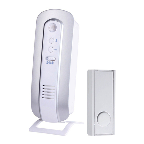
Smarti smartentry User manual

Wireless Video Doorphone
User Manual
Version 1.2
Designed & Engineered
in the United Kingdom
smartentry

Contents
Precautions ........................................................................................... 3
1. Product Overview ............................................................................. 4
1.1. Product Features ................................................................... 4
1.2. Contents ................................................................................ 4
1.3. Inserting the Battery .............................................................. 4
2. Using the smartentry ........................................................................ 8
2.1. Indoor Handset Monitor ......................................................... 8
2.2. Outdoor Camera ................................................................... 9
3. General Use ....................................................................................... 10
3.1. Observation View .................................................................. 10
3.2. Automatic Visitor Images ....................................................... 10
3.3. Tamper Alarm ........................................................................ 10
3.4. Pairing Handset & Door Bell ................................................. 11
3.5. Adding Multiple Units ............................................................. 12
4. Specifications .................................................................................... 13
5. Troubleshooting ................................................................................ 15

Thank you for purchasing the smartentry Door Entry System.
Before installing your new system, please read the instructions carefully.
3
Please charge the batteries for a minimum of 10 hours for the first time.
The smartentry accepts a power adapter and battery power, both can work at the same time.
When the smartentry is powered by the battery and power adapter at the same time, the
battery will automatically charge when the power is low.
Battery & Charger Warning
1.Only use the original charger and original batteries in your smartentry hardware.
2.Do not open the handset or outdoor phone as this may damage the product.
3.Do not crush or puncture the battery. Avoid exposing the battery to high external pressure,
which can lead to an internal short circuit and overheating.
4.Keep the battery away from extreme heat or fire
5.Keep the handset away from areas where there is high condensation and water environments.
1. Please install your system according to this manual to avoid any malfunctions or damage.
2. Never open the smartentry, please contact your installer or place of purchase in the event of
product malfunction.
3. Place the handset in a dust free, dry and well ventilated room and avoid direct sunlight.
4. Keep the handsets away from heat sources and water.
5. Never use any cleaning chemicals or wet cloth to clean the handset. Only use a dry, clean
and soft cloth/micro fibre coth.
6. Do not use the product in places where there are explosive hazards
7. Do not drop the handset or submit to heavy shaking
8. Keep chargers and power supplies away from liquids
9. Use your handset in temperature between -20 and 70° C
10. Storage temperature must be between -20 and 70° C
Safety Instructions
Precautions

1.1 Product Features
4
1. Product Overview
2.5” TFT LCD Monitor
Rechargable battery
Audio & Video transmission in real-time
Unlock Function
Anti-theft tamper alarm function
10 picture storage
Weatherproof Outdoor camera
IR LED’s for Night Vision
1.3 Inserting the Battery
1. Turn the smartentry unit around. 2. Place your finger over the arrow. Push
the back panel in and then slide down to
open.
Hand Set
1.2 Contents
1x Charging Station 2x Plug Adaptors
4x Screws
4x Wall Plugs
1x User Manual
1x Wireless Handset 1x Wireless Door
Entry Unit
1x 1m USB A
to USB Mini B Cable
(for Charging Station)
1x 1m USB
to Fly Lead
(for Outdoor Unit)
Wireless Video Doorphone
User Manual
Version1
Designed&Engineered
intheUnitedKingdom
smartentry

5
3. Locate the battery at the bottom of
the charging station.
4. Insert the battery with contacts facing
the top and insert at an angle (shown
above) and push in.
When inserted, put the back panel back
onto the handset.
1. Rear view of the base station showing
it’s USB connector. This can be used to
charge your handset’s battery.
2. If you look at the bottom of the base
station there is an Allen Key, this is used
to open the outdoor camera battey holder.
Back Wiring Diagram
You will need to drill a hole in your
mounting area for the cable to run
through.
Please note that the NO, NC and
Common are for an electric door release
(not provided) and will require additional
power. Please refer to the manual for
the electronic door release.
Charging Station
Outdoor Camera Installation & Power Lock Connection
P1: 5V Power Supply Positive P2: 5V Power Supply Negative P3: Relay Closed (NC)
P4: Common P5: Relay Open (NO)

6
1. Locate the mounting plate. Then, mark
out the holes to attach the unit and also a
centre hole where cables will run through.
2. Fix the mounting plate on the wall and
attached door entry camera to the
mounting plate using the screws provided.
How to change the battery on the Outdoor Camera
1. Front View 2. Using the allen key located in the bottom of the
charging station, open the bottom of the base of
the outdoor camera.

7
3. Slide the battery box out of the unit. 4. To re-insert the battery or a new one,
slide the battery back into the unit and
then lock the base of the unit using the
allen key.
Outside Camera Connection Guide
Input:
AC90-264V 50/60Hz
DC5V/1A
Power Adaptor
DC 5V
Unlock
Relay
Output
Lock Interface
Power On Unlock
Electronic Lock
AC 90-264V
50/60Hz
Unlock
Adaptor
DC12V 3A
Input:
AC90-264V 50/60Hz
DC5V/1A
Power Adaptor
DC 5V
AC 90-264V
50/60Hz
Unlock
Relay
Output
Power Adaptor
DC12V 3A
Lock Interface
Power O Unlock
Electronic Lock
1
2
+
-
3
4
5
NC
C
NO
1
2
+
-
3
4
5
NC
C
NO
-
+ + -

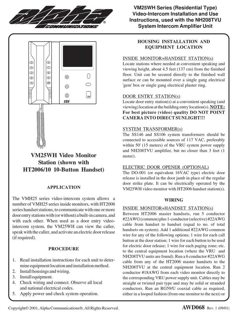
2.1 Indoor Handset Monitor
Handset Button Descriptions
On/Off/Call/Confirm
1. Answer the call of a visitor or end a conversation.
2. Press and hold this button for three seconds to power on or power off.
3. In any mode press and hold this button for 8 seconds to restore to factory default settings.
4. Once in the ‘Options’ menu, use this button to confirm selections.
8
2. Using the smartentry
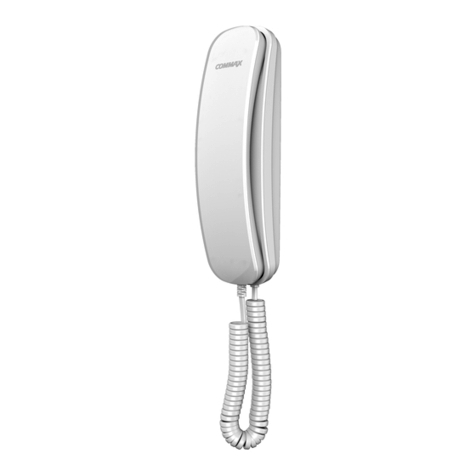
1. Speaker
3. Indicator Lamp
2. Power On
5. MIC
4. Monitor
6. Antenna
7. 2.5” Screen
8. Preview
9. Unlock
10. Charger Base
Monitor
1. In standby mode, press this button to view the outdoor monitor. Press the button for a second
time to cancel this view. Please note that the outdoor unit needs to be wired to a permanent power
source for this feature to work.
2. During a conversation, press this button to switch between ‘Video & Audio’ and ‘Audio Only’
mode.
3. After entering the ‘Options menu’, press this button to exit.
Preview
1. In standby mode, press this button to view the visitor history images.
2. When viewing image history, use this button to scroll up through the images.
Unlock
1. When a visitor calls, you can use this button to unlock the electronic lock on your door if you
have one pre-fitted.
2. When viewing image history, use this button to scroll down through the images.
3. When the handset is connected to the charging station or computer (using USB), press this
button to go to the ‘Options’ menu.

9
Handset Indicator Description
Standby: Blue light will flash every 4 seconds
Low Power: Blue light will flash every second.
Charging: Red light will flash every 4 seconds. The screen displays the battery charging symbol.
Full Power: Red light is on constant, the screen will display the battery full symbol.
Low Power of outdoor monitor: Screen will display ‘OUT LOW POWER’.
Calling: Both red and blue light will be on.
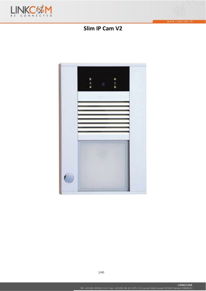
2.2 Outdoor Camera
1. Rain Cover
3. Speaker
2. Infrared Camera
5. Status Light
4. Call Button
6. Antenna
8. Tamper Alarm
7. Microphone
Camera Description
Call Button: Visitors can press this button to call the handset.
Infrared Camera: The camera will activate as soon as the visitor presses the button. The Infrared
LED’s on the camera will activate automatically when in low light.
Clear code button/
Stop tamper alarm
Outdoor Monitor Indicator Description
Standby: When supplied by external power, the blue light will flash 4 times per second. If
supplied by battery, the light will not flash.
Calling: Blue light will be on constantly.
Low Battery: Blue light will flash every second. The screen on the handset will display ‘OUT LOW
POWER’.

3.2 Automatic Visitor Images
The system will automatically save images of visitors when they call. In standby mode, press the
or buttons to view the image history.
The image indicates that you have a new visitor in the image history.
The unit will store 10 visitor images before overwriting the oldest one.
PLEASE NOTE: If you remove the battery or the battery runs out, you will lose all stored images.
10
1. When a visitor presses the outside doorbell, the internal handset will ring.
2. When the handset is ringing, press the button to answer the call within 40 seconds. If the
call is not answered, the unit will make one beep sound and save the visitor image. The
maximum talk time, if answered, is 120 seconds.
3. When you answer the call the handset will be in ‘Audio Mode’, you can press the button to
switch to ‘Video Mode’. The video call will last for 7 seconds.
4. During the conversation you can unlock the door by pressing the button. (This will only
work if you have connected an electronic door lock). (Not supplied)
5. Pressing the button will end the conversation and the system will return to standby mode.
3.1 Observation View
1. In standby mode, press the button to view outside through the camera, even when there is
nobody at the door. When doing this, the handset screen will display ‘MONITOR’.
2. Press the button to select ‘TALK ON’ or ‘TALK OFF’.
3. Press the button to exit.
3. General Use
3.3 Tamper Alarm
If the outdoor unit is tampered with, it will sound an alarm to alert you. You can clear this alarm in 2
ways:
1. Press the button.
2. Press the clear mode button on the base of the camera, shown on the base image on page 9.

11
3.4 Pairing Handset & Door Bell
The SMARTENTRY system has been setup and paired for you. However, should you purchase
any additional handsets or monitors or need to pair them again, please follow the steps below.
Clear Pairing Code (Handset)
1. Make sure the handset has at least 50% battery. The handset will need to either be in the
charging station, or powered by USB to enter the menu.
2. Press the button to enter the ‘Options’ menu and then press the or buttons to go
to the clear code menu. Then, press to confirm the ‘CLEAR CODE’ command.
3. Input the correct password (Default is 0000) by using the or buttons. When entering
the password, press the to move position.
4. Press the button to confirm clear code.
5. Once the screen displays ‘Clear code succeeded’, move on to the next section.
Clear Pairing Code (Outside Camera Unit)
1. Use the allen key found in the bottom of the charging station and remove the bottom panel from
the outside unit.
2. Remove the battery box.
3. Use the top of the allen key to press and hold the ‘Clear Code’ (shown on page 9) button for
about 10 seconds. At the same time, put the battery box back into the unit.
4. Keep the button pressed until you hear 2 double beep sounds and then you can release the
button.
5. After releasing the button, wait until the outside camera unit beeps 3 times. When it has done
this, you can move on to the next section.

3.5 Adding Multiple Units
Match Codes
1. Firstly, press the button on the handset to enter the main menu.
2. Press the or buttons to go to the match code menu. Then press the to confirm
the ‘Match Code’.
3. Press and hold the ‘clear code’ button of the outdoor camera unit. Press for around 5 seconds
until the unit beeps twice. Then release the button and the outdoor unit will automatically go to
‘Match Code’ mode.
4. If coding is successful, the outdoor unit sounds three times and the handset will go into the
standby mode. Then, reboot both units and they should be paired.
12
To add more handsets and outside cameras together, please follow the steps below.
Firstly, clear the codes on the new handset or camera. This is shown in the previous section.
ADD a new Handset
1. Access the ‘Options’ menu on the already paired Handset by pressing the button. Use the
button to navigate down to the ‘Give Code’ option and press the button to confirm. The
screen will show ‘Giving Screen Status’.
2. On the new handset, press the button to open the ‘Options’ menu. Use the button to
navigate down to the ‘Receive Code’ option and press the button to confirm. The screen will
display ‘Match Code Succeeded’, if it has found the other handset.
ADD a new Outdoor Monitor
1. Access the ‘Options’ menu on the already paired Handset by pressing the button. Use the
button to navigate down to the ‘Give Code’ option and press the button to confirm. The
screen will show ‘Giving Screen Status’.
2. On the new outdoor unit, press and hold the ‘Clear Code’ button under the screw flap. Please
note that the unit has to be powered, so please do not remove the battery.
Press the button for around 5 seconds until you hear a double beep sound. Release the button,
and the unit will automatically go to ‘Match Code’ mode.
If the above fails, please repeat the steps. If successful, power cycle all the units and test.

13
4. Specifications
smartentry (Indoor Monitor) Specifications
External Power
Li-ion Battery Power
Shutdown Current
Average Working Current
Standby Current
Receive Sensitivity
Charging Current
Charging Time
5V 1000mA
3.7V 1400mA
200UA
260mA
4-8mA
-100dBm
600mA
3 Hours
Operating Temperature -20~70°C
Working Voltage USB 5V (External Power)
3.7V-4.2V (Li-ion battery power)
Transmission Power 18-20dBm
Transmission Distance
(Line of Sight)
500m (Audio)
300m (Video & Audio)

14
smartentry (Outdoor Camera) Specifications
External Power
Li-ion Battery Power
Shutdown Current
Average Working Current
Standby Current
Receive Sensitivity
Charging Current
Charging Time
5V 1000mA
3.7V 1400mA
0mA
340mA
15-18mA (External Power)
0mA (Li-ion battery power)
-100dBm
600mA
3 Hours
Operating Temperature -20~70°C
Working Voltage DC 5V (External Power)
3.7V-4.2V (Li-ion battery power)
Transmission Power 18-20dBm
Transmission Distance
(Line of Sight)
500m (Audio)
300m (Video & Audio)
smartentry (Charging Station) Specifications
External Power
Charging Current
Operating Temperature
USB 5V
200mA
-20~70°C

15
5. Troubleshooting
Problem
Sound/Image
is intermittent
Check
Check if there is enough power
going to the unit.
Recharge or replace the
battery.
Solution
Check if the units are outside of
the workable range
Move the units within the
500/300m line of sight.
No
Communication
Check if there is enough power
going to the unit.
Recharge or replace the
battery or replace external
power.
Check if the codes are clear on
the units and they are paired.
Match the codes again.
Can’t unlock the
door
Check the connection of the lock
on the door.
Re-connect the door lock.
Check if the lock is faulty If faultly, replace the lock.
Radio Signal
Propagation of radio waves or radio frequency are used for wireless communication between
outdoor and indoor stations.
The performance of wireless communcation depends on the environment where it is installed.
Radio coverage quality will be affected by possible blockage between transmitter and receiver.
These can included walls, concrete, metal (Armored doors, elevator shafts etc), plasterboard,
wood and various other materials.
Please note that not only visible obstructions can affect the wirelss quality. Interference can
also come from electric or electromagnetic devices such as wireless routers, microwave ovens,
TV’s and similar devices. The smartentry operates on 2.4GHz frequency. You can help
minimize interference by changing the WIFI channel on your wireless router (Please refer to
your router’s user manual for information on this). We also recommend you to test the system
before deciding your final installation position
It is important to test the wireless coverage on site before installing the smartentry.
Please see the following page for some examples of materials how they affect the wireless
signal.

16
Plasterboard & Wood
10-30% signal reduction
Brick
30-50% signal reduction
Concrete & Building Blocks
50-70% signal reduction
Metal & Metal Cladding
70-90% signal reduction
PLEASE NOTE: Before mounting any piece of the smartentry, please test the unit.

17
Manufactured for:
Designed & Engineered
in the United Kingdom
Smart-i, Unit 2 Valley Point, Beddington Farm Road, Croydon Surrey CR0 4WP
Table of contents
