SMDT IoT-3399E User manual
Shenzhen Smart Device Technology Co.,Ltd
IoT-3399E
USER MANUAL
Modification History
Version Description Date
V1.0 Creation 2017-07-12
V1.1 Modify 2017-09-20
V2.0 Modify 2018-06-27

Shenzhen Smart Device Technology Co.,Ltd
Catalogue
Chapter 1. Production General Description ..................................................................... 3
1.1 Scope of Application....................................................................................... 3
1.2 General Description........................................................................................ 3
1.3 Features ......................................................................................................... 3
1.4 Appearance and Interface Sketch................................................................... 4
Chapter 2. Basic Function List.......................................................................................... 5
Chapter 3.PCB Measurement And Interface Layout........................................................ 6
3.1 PCB Measurement Chart................................................................................ 6
3.2 Interface Parameter Definition........................................................................ 8
Chapter 4. Electric Performance ......................................................................................21
Chapter 5 Assembly Using Notice ...................................................................................23

Shenzhen Smart Device Technology Co.,Ltd
Chapter 1. Production General Description
1.1 Scope of Application
IoT3399E belongs to android smart mainboard, generally applicable to smart display
terminal products, video terminal products, industrial automation terminal products,
such as: advertising machine, digital signage, smart self-service termina, smart retail
terminal, O2O smart device , Industrial control PC, robot device etc
1.2 General Description
IoT-3399E uses Rockchip RK3399 Big.Little architecture: Dual Cortex-A72 + Quad
Cortex-A53, 64-bit CPU,carries Android 7.1 system, main frequency 2.0GHz,
outstanding properties.Using Mali-T864GPU, support 4K, H.265 hard decoding.
Multi-channel video output and input for better performance, faster speed and richer
interfaces ,it is the best choice for your man-machine interactive,industrial projects.
1.3 Features
RK3399 super CPU with Android 7.1 system, faster speed, better performance.
Support 5G and 2.4GWIFI, independent dual antenna
Support 1000M ethernet port
Rich extension interface: 8 USB interfaces( 6 insert pin, 2 standard USB interface), 4
extensible serial port(3* RS232,1*TTL), 1*485 interfaces ,4*GPIO and ADC interface,
it can meet the requirements of various peripherals in the market.
High definition. Maximum support 3840x2160 4K decoding and all kinds of LCD
screen with LVDS/eDP/HDMI etc interface,support each size and different resolution
cropping screen, Support dual screen display.
Support Android system customized, provide system invocation interface API
reference source code, support clients upper application development perfectly.
Perfect support IR, optics,capacitive, resistance, touch foil etc multiple mainstream
touch screen,support non driver touch screen HID configuration without debugging.

Shenzhen Smart Device Technology Co.,Ltd
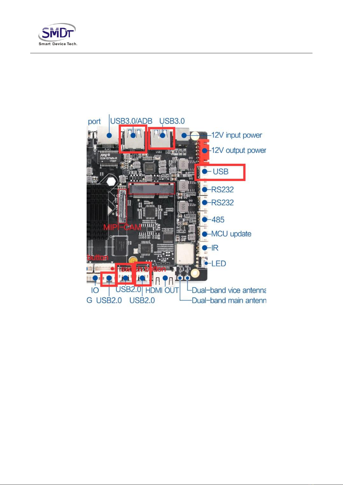
1.4 Appearance and Interface Sketch
Shenzhen Smart Device Technology Co.,Ltd
Chapter 2. Basic Function List
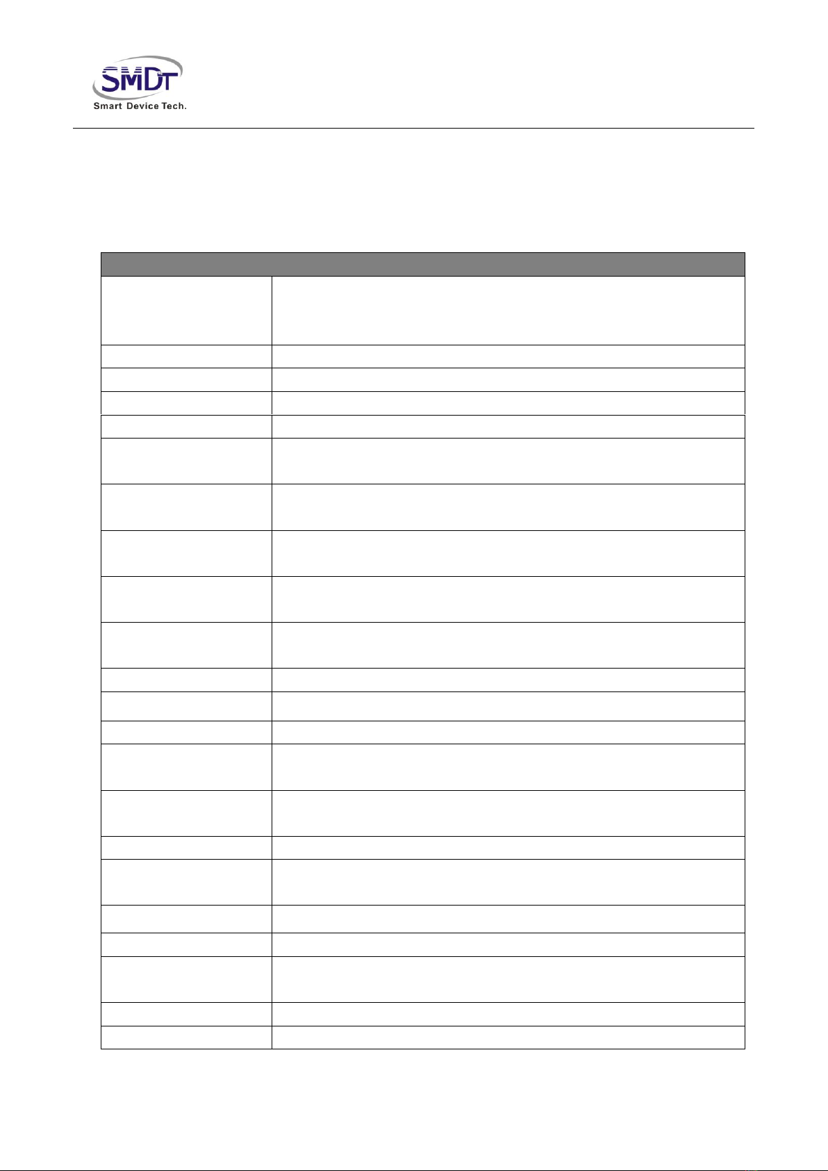
Main Hardware Index
CPU Rockchip RK3399 64-bit CPU, main frequency 2.0GHz
1.Big.Little architecture: Dual Cortex-A72 + Quad Cortex-A53
2.Built-in low power consumption MCU Cortex-M0
GPU Quad Cortex- Mali-T860MP4
Internal Memory Standard configuration 2G(4G optional)
Built-in Storage Standard configuration 8G(16/32/64G optional)
Built-in ROM 2KB EEPROM
LVDS output 1 single/double channel,can drive 50/60Hz LCD panel directly
eDP output Can drive many kinds of resolution LCD panel with eDP
interface
HDMI output 1,support 1080P@120Hz,4kx2k@60Hz output
HDMI input Support HDMI IN(can select TF card slot)
Audio and Video
ouput Support left and right channels output, built-in dual
4R/20W,8R/10W amplifier
Earphone Support one channel earphone interface
USB interface 2*USB 3.0, 6*USB Socket
Serial port 5 channels serial port (3*232,1*TTL,1*485)
Mipi Camera 30pin FPC interface,Support 1300w Camera
WIFI、BT Built-in WIFI, BT4.0(optional)
Ethernet 1000M self-adapting Ethernet
Video Playing Support wmv、avi、flv、rm、rmvb、mpeg 、ts、mp4, etc
Image Format Support BMP, JPEG, PNG, GIF
Operating System Android 7.1
RTC Real Time
Clock Support
Timing Switch Support
System Upgrade Support local SD,USB upgrade

Shenzhen Smart Device Technology Co.,Ltd
Chapter 3.PCB Measurement And Interface
Layout
3.1 PCB Measurement Chart

Shenzhen Smart Device Technology Co.,Ltd
PCB:8 layers
Measurement:146mm*100mm, thickness1.6mm
Screw hole specification:∮3.2mm x 4

Shenzhen Smart Device Technology Co.,Ltd
3.2 Interface Parameter Definition
◆Power Input Port
Use 12V DC power supply,only allowed from the DC power supply and power socket to power the
board system ,the plug of the power adapter DC IN specifications is D6.0,d2.0.
(outerΦ4.4mm,PINΦ1.65mm),without in a peripheral empty load cases,12V dc power supply to
support the minimum current 600 mA.
Power socket interfaces are defined as follows,can use power panel power supply,the socket
specifications is 6 pin 2.54 mm spacing.
NO. Definition Property Description
1 VCC input 12V input
2 VCC input 12V input
3 GND ground
electrode
ground electrode
4 GND ground
electrode
ground electrode
5 VCC-5V input standby 5V input
6 STB output standby signal output
Standby 5V input & standby signal output is used as standby power supply board,if want to do low
standby power consumption,the standby 5V input & standby signal output signal respectively
connected with the 5 v power supply board STB and PS_ON(the description of the two signals might
be different from different suppliers of power supply board,Please refer to the actual), If you don't
need to do low standby power consumption,then no need to connect the 2 pins.

Shenzhen Smart Device Technology Co.,Ltd
◆BAT1 RTC Battery Port
used to install the clock battery,supply power to the system clock when power outages.
NO. Definition Property Description
1 RTC input 3V input
2 GND ground
electrode
ground electrode
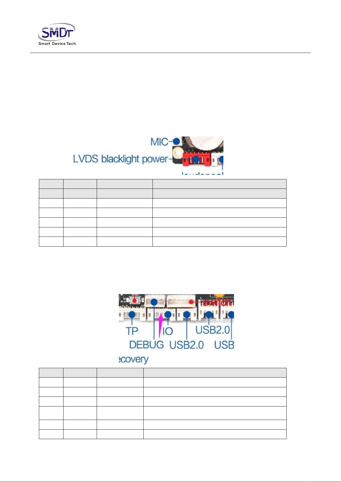
◆MIC Port
Please note that the MIC is positive negative connection,not reverse.
NO. Definition Property Description
1 MIC- input MIC-
2 MIC+ input MIC+
◆Port Of Receiving Remote Control
NO. Definition Property Description
1 IR input remote control signal input
2 GND ground
electrode
ground electrode
3 3V3 Power 3.3V output

Shenzhen Smart Device Technology Co.,Ltd
◆Work Indicating Lamps
The default support gongyang red blue double LED lights.
NO. Definition Property Description
1 LED_B Blue light Work light
2 VCC Power supply 3.3V output
3 LED_R Red light Standby lamp
◆LED/IR Port
The position of remote control receiving and indicating light is shared(can choose welding 2.54 mm
spacing of 7 pins socket).
NO. Definition Property Description
1 LED_B output work indicating lamp
2 VCC power 3.3V output
3 LED_R output standby indicating lamp
4 ADC ADC input ADC button input
5 IR input remote control signal input
6 GND ground
electrode
ground electrode
7 3.3V power 3.3V output
Shenzhen Smart Device Technology Co.,Ltd
◆Backlight Control Port
Use for LVDS screen backlight control,the 12V power supply current is not more than 1.5A,When
using more than 19 inch screen or screen backlight power in more than 20W,backlight power supply
electricity is taken from the other power plate,so as not to cause system instability. Backlight can make
voltage is 5V,if other voltage, please add IO level conversion circuit. The 12V power supply only as a backlight power
output, don't as a power input supply system.
NO. Definition Property Description
1 GND ground electrode ground electrode
2 GND ground electrode ground electrode
3 BL-ADJ output backlight brightness adjust control
4 BL-EN output backlight enable control
5 VCC power 12V output
6 VCC power 12V output
◆IO Interface
I/O used for provide peripherals with input/output for controlling signal. Electrical level is 3.3V.
NO. Definition Property Description
1 VCC power 3.3V output
2 I/O input/output GPIO-1
3 I/O input/output GPIO-2
4 I/O input/output GPIO-3
5 I/O input/output GPIO-4
6 GND ground electrode ground electrode
Shenzhen Smart Device Technology Co.,Ltd
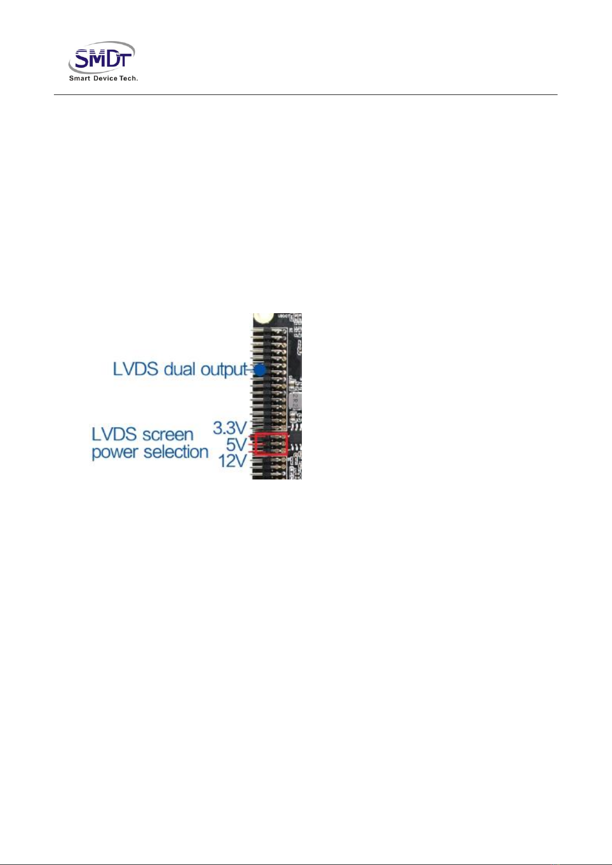
◆LVDS Port
Commonly used LVDS interface definitions,support single/ double channels,6/8/10 bits 1080P LVDS
screen. Screen voltage can be choosed by jumper cap,can choose to support 3.3V/5V/12V screen
power supply.
In order to avoid burning board and screen, please pay attention to the following:
1.Please make sure the specifications and power supply voltage of the screen is correct, the power
supply of the board can meet the maximum current screen work accordingly
2.Please confirm the power of the jumper cap is correct by multimeter.

Shenzhen Smart Device Technology Co.,Ltd
The selection of screen power supply with jumper cap in above photo, from top to bottom :3.3V/5V/12V.
NO. Definition Property Description
1
PVCC Power output LCD power output,+3.3v/+5V/ +12V Optional
2
3
4
GND ground electrode ground electrode5
6
7 D0N Output Pixel0 Negative Data (Odd)
8 D0P Output Pixel0 Positive Data (Odd)
9 D1N Output Pixel1 Negative Data (Odd)
10 D1P Output Pixel1 Positive Data (Odd)
11 D2N Output Pixel2 Negative Data (Odd)
12 D2P Output Pixel2 Positive Data (Odd)
13 GND ground electrode ground electrode
14 GND ground electrode ground electrode
15 CLK0N Output Negative Sampling Clock (Odd)
16 CLK0P Output Positive Sampling Clock (Odd)
17 D3N Output Pixel3 Negative Data (Odd)
18 D3P Output Pixel3 Positive Data (Odd)
19 D5N Output Pixel0 Negative Data (Even)
20 D5P Output Pixel0 Positive Data (Even)
21 D6N Output Pixel1 Negative Data (Even)
22 D6P Output Pixel1 Positive Data (Even)
23 D7N Output Pixel2 Negative Data (Even)
24 D7P Output Pixel2 Positive Data (Even)
25 GND ground electrode ground electrode
26 GND ground electrode ground electrode
27 CLK1N Output Negative Sampling Clock (Even)
28 CLK1P Output Positive Sampling Clock (Even)
29 D8N Output Pixel3 Negative Data (Even)
30 D8P Output Pixel3 Positive Data (Even)

Shenzhen Smart Device Technology Co.,Ltd
◆232 Serial port interface*2
Led out of the two sets of ordinary 232 serial port, can support the general market of the 232 serial
devices.
Remark:
1.Serial voltage matching, Cannot access directly TTL,485 serial device.
2.TX,RX whether the connection is correct.
NO. Definition Property Description
1 GND ground electrode ground electrode
2 232-RXn input 232-RX
3 232-TXn output 232-TX
4 VCC Power supply 5V output
◆TTL Wires Serial Socket Port*1
The board raises a common one wires of serial ports,can support general serial port devices on the
market,level of the serial port is 0V to 3.3V.If the abutting serial level higher than 3.3 V,must have the
isolating circuit or level conversion circuit, otherwise it will burn out master and equipment.
Notice:
1.If TTL serial port voltage can match or not, can't directly access MAX232,485 devices.
2.TX,RX connection if is correct.
Shenzhen Smart Device Technology Co.,Ltd
NO. Definition Property Description
1 GND ground
electrode
ground electrode
2 UART-RX input/output RX
3 UART-TX input/output TX
4 VCC Power supply 3.3V output
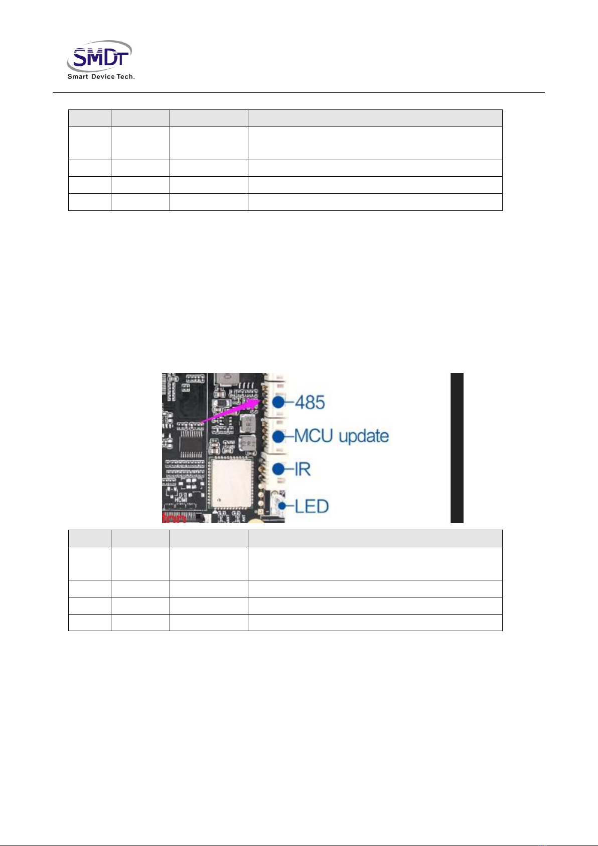
◆485
Support 1 set of 485 communication interfaces, It can support the common 485 interface devices
on the market, interface level is 3.3V, When the interface level is higher than 3.3v, there should be an
isolated circuit or a level conversion circuit, otherwise the main control and equipment will be burnt
out.
1.485 interface voltage is matched.
2.485A, 485B line sequence connection method is correct.
NO. Definition Property Description
1 GND ground
electrode
ground electrode
2 485B input/output RX
3 485A input/output TX
4 VCC Power supply 3.3V output
Shenzhen Smart Device Technology Co.,Ltd
◆USB
The board has 2 standard USB 3.0interface,including 6inbuilt USB socket,can be used for peripheral
expansion,default to HOST,each interface power supply current is not more than 500mA,for USB
OTG interface,can select the Host/Device by System settings.

Shenzhen Smart Device Technology Co.,Ltd
USB There are two kinds of sockets :One kind is single row pin ,Electrical definitions are as follows:
NO. Definition Property Description
4 VCC Power supply 5V output
3 DM input/output DM
2 DP input/output DP
1 GND ground
electrode
ground electrode
The other is a double row pin, electrical definitions such as J23 are as follows:
NO. Definition Property Description
1 VCC Power supply 5V output
2 DM input/output DM
3 DP input/output DP
4 GND ground
electrode
ground electrode
5 VCC Power supply 5V output
6 DM input/output DM
7 DP input/output DP
8 GND ground
electrode
ground electrode
◆Touch screen interface
Shenzhen Smart Device Technology Co.,Ltd
NO. Definition Property Description
1 VCC Power supply 3.3V output
2 SCK input/output I2C clock
3 SDA input/output I2C data
4 INT input/output interrupt
5 RST input/output reset
6 GND ground
electrode
ground electrode
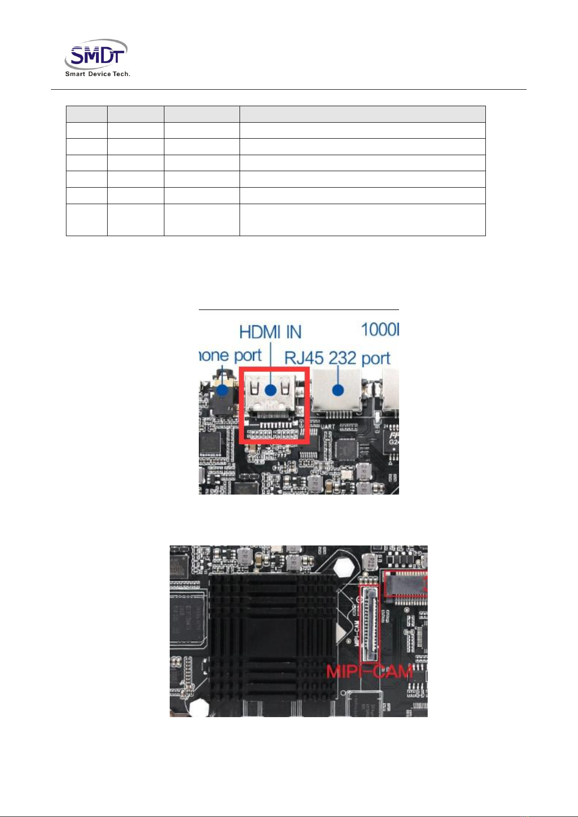
◆HDMI_IN Interface
HDMI_IN and TF card Alternative interface
◆Camera_IN Interface

Shenzhen Smart Device Technology Co.,Ltd
Board support 1400W pixel Mipi camera,Installed in jp26 socket ,the electrical definition of the socket is as follows:
NO. Definition Property Description
1 NC / /
2 VDD Power supply 2.8V output
3 DVDD Power supply 1.2V output
4 DOVDD Power supply 1.8V output
5 NC / /
6 GND ground electrode ground electrode
7 VDD Power supply 2.8V output
8 GND ground electrode ground electrode
9 I2C3_SDA input/output SDA signal
10 I2C3_SCL output SCL signal
11 RST output reset signal
12 PWDN output Power down control
13 GND ground electrode ground electrode
14 MCLK output Master clock
15 GND ground electrode ground electrode
16 D3P input/output mipi data channel3 plus
17 D3N input/output mip data channel3 minus
18 GND ground electrode ground electrode
19 D2P input/output mipi data channel2 plus
20 D2N input/output mipi data channel2 minus
21 GND ground electrode ground electrode
22 D1P input/output Mipi data channel 1 plus
23 D1N input/output Mipi data channel 1 minus
24 GND ground electrode ground electrode
25 CLKP input/output Mipi Clock channel plus
26 CLKN input/output Mipi Clock channel minus
27 GND ground electrode ground electrode
28 D0P input/output Mipi data channel 0 plus
29 D0N input/output Mipi data channel 0 minus
30 GND ground electrode ground electrode

Shenzhen Smart Device Technology Co.,Ltd
◆Speaker interface
NO. Definition Property Description
1 OUTP-L output Audio output left +
2 OUTN-L output Audio output left -
3 OUTN-R output Audio output right -
4 OUTP-R output Audio output right +
◆Other standard interfaces and functions :
Memory Port
SD card Data storage, maximum support 32G
USB Host port, support data storage, data input, USB,
mouse keyboard, camera, touch screen etc
Ethernet Port RJ45 port Support 1000M wire network
HDMI Port Standard port support HDMI data output, maximum support 1080P
Earphone Port Standard port 3.5mm standard port
Table of contents


