User's Guide
SLAU355A–July 2011–Revised March 2015
ADS5294, 8-Channel, Analog-to-Digital Converter
Evaluation Module
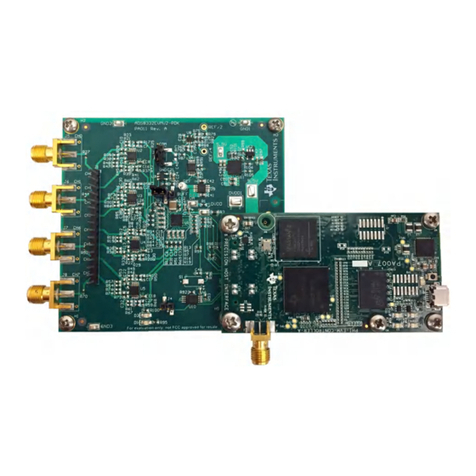
This user’s guide gives a general overview of the evaluation module (EVM) and provides a general
description of the features and functions to be considered while using this module. This manual is
applicable to the ADS5294 analog-to-digital converters (ADC), which collectively are referred to as
ADS529x. Use this document in combination with the respective ADC data sheet. The ADS529xEVM
provides a platform for evaluating the ADC under various signal, clock, reference, and power supply
conditions.
Contents
1 Quick View of Evaluation Setup ........................................................................................... 3
2 Default Configuration........................................................................................................ 4
3 Software Installation and Operation....................................................................................... 5
3.1 GUI Installation – Mandatory...................................................................................... 5
3.2 USB Interface Driver Installation.................................................................................. 5
4 Test Setup .................................................................................................................... 6
5 Power Up ADS5294......................................................................................................... 7
6 Launch ADS5294 GUI ...................................................................................................... 8
7 Launch TSW1400 GUI..................................................................................................... 11
8 TEST ADS5294............................................................................................................. 12
8.1 Step 2: Single Tone FFT ......................................................................................... 15
9 Board Configuration........................................................................................................ 17
9.1 Input/Output, Power Supply, and USB ......................................................................... 17
9.2 ADC Clock.......................................................................................................... 19
9.3 Light-Emitting Diodes............................................................................................. 21
9.4 Miscellaneous Test Points ....................................................................................... 22
10 EVM Schematics ........................................................................................................... 23
11 ADS5294EVM Bill of Materials ........................................................................................... 31
12 ADS5294EVM Printed-Circuit Board Layout............................................................................ 33
Appendix A High Speed Data Converter Pro (HSDCPro) GUI Installation............................................... 41
List of Figures
1 Evaluation Setup............................................................................................................. 3
2 ADS5294EVM Basic Configuration........................................................................................ 4
3 HW Setup With Connection Between TSW1400EVM and ADS5294EVM........................................... 7
4 Power-Up Indications........................................................................................................ 8
5 ADS5294 GUI Launch ...................................................................................................... 9
6 TSW1400 GUI Launch..................................................................................................... 11
7 ADS5294 Time Domain Setup ........................................................................................... 12
8 ADS5294 Test Pattern..................................................................................................... 13
9 User Interface: Time Domain Format.................................................................................... 14
10 User Interface: Single FFT Format....................................................................................... 16
11 I/O, PWR, and USB Connector........................................................................................... 17
12 ADS5294EVM Default Clock Jumper Locations ...................................................................... 19
13 ADS5294EVM LED Location ............................................................................................ 21
Windows, Microsoft are trademarks of Microsoft Corporation.
1
SLAU355A–July 2011–Revised March 2015 ADS5294, 8-Channel, Analog-to-Digital Converter Evaluation Module
Submit Documentation Feedback Copyright © 2011–2015, Texas Instruments Incorporated
