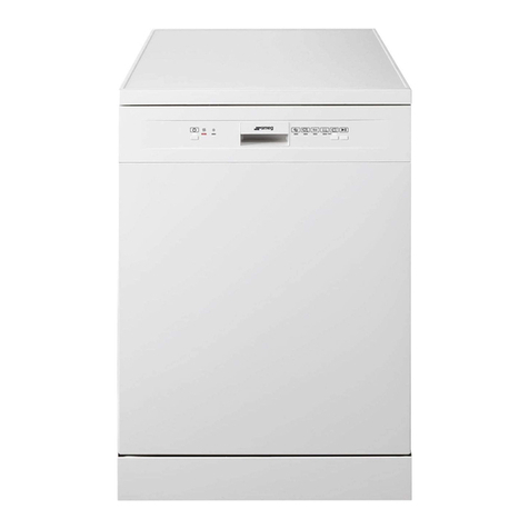
Smeg CW 420 User manual

PROFESSIONAL DISHWASHER

CONTENTS
1 PRECAUTIONS FOR SAFETY AND USE ........................................................................... 3
2 TECHNICAL DATA ......................................................................................................... 5
3 INSTALLATION AND POSITIONING................................................................................ 7
4 INSTRUCTIONS FOR TECHNICAL STAFF ......................................................................... 8
4.1 Plumbi g hookup ................................................................................................... 8
4.2 Electrical co ectio .............................................................................................. 9
5 FIRST START-UP.......................................................................................................... 11
5.1 Ri se aid dispe si g setti g (o models with diaphragm pump with ma ual
setti g o ly) .................................................................................................................. 12
5.2 Usi g the water softe er (o models with this feature o ly) ............................... 13
6 SET-UP ....................................................................................................................... 14
6.1 Dishwasher parameter modificatio procedure: ................................................. 14
6.2 Quit “ SET-UP “ me u .......................................................................................... 16
6.3 Ri si g temperature setup .................................................................................. 16
6.4 Washi g temperature setup ................................................................................ 16
6.5 Deterge t dispe si g setup (if featured) ............................................................. 17
6.6 Ri se aid dispe si g setup (if featured) ............................................................... 17
6.7 Autostart fu ctio ............................................................................................... 17
6.8 Rege eratio freque cy setup (models with softe er) ........................................ 18
6.9 tStP (mi imum ri si g temperature) fu ctio ..................................................... 18
6.10 Ri se aid pump (display a d if required reset duri g mai te a ce) (if featured)
19
6.11 Deterge t pump (display a d if required reset duri g mai te a ce) (if featured)
19
6.12 E ergy co sumptio – Display a d reset if required ......................................... 19
6.13 Service setti g (for After-Sales Service o ly) ..................................................... 19

- CW 420/430
2
6.14 Starti g the peristaltic pumps – rapid filli g of deterge t a d ri se aid delivery
circuit.(if featured) ........................................................................................................ 19
7 MALFUNCTIONS SHOWN ON THE DISPLAY (FOR THE TECHNICIAN) ........................... 20
8 INSTRUCTIONS FOR THE USER ................................................................................... 22
8.1 Co trol pa el ....................................................................................................... 22
8.2 Before washi g .................................................................................................... 22
8.3 First use each day (ta k a d boiler empty) .......................................................... 23
8.4 Cha gi g the Program ......................................................................................... 24
9 CHOOSING THE PROGRAM ........................................................................................ 25
10 SUPPLEMENTARY FUNCTIONS ................................................................................ 26
10.1 Selecti g the crys“glassware” fu ctio (available i P1-P2) .............................. 26
10.2 Selecti g the “extra ri se” fu ctio (available i P1-P2-P3-P4) ......................... 26
10.3 Selecti g the “sa itisatio ” fu ctio (o ly available i P3) ............................... 27
11 MAINTENANCE AND CLEANING .............................................................................. 29
11.1 Daily clea i g .................................................................................................... 29
11.2 Routi e i spectio of the spray arms ............................................................... 30
11.3 Le gthy periods out of use ............................................................................... 30
12 TROUBLESHOOTING ................................................................................................ 31
13 MALFUNCTIONS SHOWN ON THE DISPLAY (FOR THE USER) ................................... 33

- CW 420/430
3
SMEG thanks you for choosi g o e of its products.
Read all the i structio s i this ma ual carefully to become familiar with the right co ditio s for the
proper use of your dishwasher.
TECHNICAL INSTRUCTIONS
INSTRUCTIONS FOR THE USER
1 PRECAUTIONS FOR SAFETY AND USE
THE DISHWASHER IS INTENDED FOR PROFESSIONAL USE ONLY AND MUST ONLY BE USED BY
AUTHORISED STAFF. IT IS DESIGNED TO WASH TABLEWARE (PLATES, CUPS, BOWLS, OVEN DISHES
AND CUTLERY) AND SIMILAR ITEMS IN THE RESTAURANT AND INSTITUTIONAL CATERING SECTOR,
AND COMPLIES WITH THE INTERNATIONAL STANDARDS ON ELECTRICAL AND MECHANICAL SAFETY
(CEI-EN-IEC 60335-2-58/6 770) AND ELECTROMAGNETIC COMPATIBILITY (CEI-IEC-EN 550 4- /-2,
6 000-3;4, 50366).
These are i te ded for the qualified staff who are to i stall, commissio a d test
the applia ce a d carry out a y servici g a d repairs.
These provide recomme datio s for use, a descriptio of the co trols a d the
correct procedures for clea i g a d mai tai i g the dishwasher.
THIS MANUAL IS AN INTEGRAL PART OF THE DISHWASHER AND MUST ALWAYS BE
KEPT INTACT TOGETHER WITH THE APPLIANCE.
POSITIONING, HOOKUP, COMMISSIONING, TROUBLESHOOTING AND REPLACING THE
POWER CABLE MUST ALWAYS BE CARRIED OUT BY QUALIFIED STAFF.
THE APPLIANCE MUST BE GROUNDED AS REQUIRED BY ELECTRICAL EQUIPMENT
SAFETY STANDARDS.

- CW 420/430
4
THE MANUFACTURER DECLINES ALL RESPONSIBILITY FOR INJURY OR DAMAGE CAUSED BY FAILURE
TO COMPLY WITH THE INSTRUCTIONS IN THE MANUAL, BY INCORRECT USE, BY TAMPERING WITH
EVEN JUST ONE PART OF THE APPLIANCE AND BY THE USE OF NON-ORIGINAL SPARE PARTS .
THIS APPLIANCE IS TAGGED UNDER EUROPEAN DIRECTIVE 2002/96/EC ON WASTE ELECTRICAL AND
ELECTRONIC EQUIPMENT (WEE).
BY MAKING SURE THAT THIS PRODUCT IS DISPOSED OF CORRECTLY THE USER HELPS TO PREVENT
POTENTIAL DETRIMENTAL EFFECTS ON HEALTH AND THE ENVIRONMENT.
WHEN DECOMMISSIONING THE APPLIANCE COMPLY WITH THE LOCAL WASTE DISPOSAL
REGULATIONS.
FOR FURTHER INFORMATION ON THE TREATMENT, RECOVERY AND RECYCLING OF THIS PRODUCT,
CONTACT THE COMPETENT LOCAL OFFICE, THE DOMESTIC WASTE COLLECTION SERVICE, OR THE
SHOP WHERE THE PRODUCT WAS PURCHASED.
THE SYMBOL OF THE RUBBISH BIN WITH A BAR ACROSS IT ON THE PRODUCT OR IN THE
TECHNICAL DOCUMENTATION INDICATES THAT THIS PRODUCT MUST NOT BE TREATED
AS ORDINARY DOMESTIC WASTE BUT MUST BE CONSIGNED TO THE SPECIAL
COLLECTION POINT FOR THE RECYCLING OF ELECTRICAL AND ELECTRONIC EQUIPMENT.
NEVER PLACE SOLVENTS SUCH AS ALCOHOL OR TURPENTINE, WHICH MIGHT CAUSE AN
EXPLOSION, INSIDE THE APPLIANCE. NEVER LOAD DISHES DIRTY WITH ASH, WAX OR
PAINTS.
NEVER USE THE DISHWASHER OR ANY PART OF IT AS A LADDER, SUPPORT OR STAND
FOR PEOPLE, ANIMALS OR ANY OBJECT.
LEANING OR SITTING ON THE OPEN DOOR OF THE DISHWASHER MIGHT CAUSE IT TO TIP
OVER, PUTTING PEOPLE IN DANGER.
NEVER LEAVE THE DISHWASHER DOOR OPEN SINCE PEOPLE MIGHT TRIP OVER IT.
DO NOT DRINK ANY WATER LEFT IN THE DISHES OR DISHWASHER AT THE END OF THE
WASHING PROGRAM.
THE APPLIANCE IS NOT SUITABLE FOR USE BY JUVENILES OR PERSONS WITH REDUCED
PHYSICAL, SENSORIAL OR MENTAL CAPACITIES, OR THOSE WITHOUT THE NECESSARY
KNOWLEDGE AND EXPERIENCE. SUCH PERSONS MAY ONLY USE THE APPLIANCE UNDER
THE SUPERVISION OF A PERSON RESPONSIBLE FOR THEIR SAFETY.

- CW 420/430
5
2 TECHNICAL DATA
Supply voltage V 400V 3N ~
Co vertible to si gle-phase versio V 230V 1N ~
Freque cy Hz 50
Max. power absorptio at 400V 3N ~(3 bra ches of heati g
eleme t)
kW 4.8
Max. power absorptio at 230V 1N ~(2 bra ches of heati g
eleme t)
kW 3.3
Max. power absorptio at 230V 1N ~(1 bra ch of heati g
eleme t)
kW 1.8
Boiler heati g eleme t power at 400V 3N ~(3 bra ches of
heati g eleme t)
kW 4.5
Boiler heati g eleme t power at 230V 1N ~(1 bra ch of
heati g eleme t)
kW 1.5
Ta k heati g eleme t power kW 0.8
Water i take pressure kPa (bar) 100-600 (1 ÷ 6)
Water i take temperature °C 15°C – 60°C
Water hard ess (o models with softe er <60°f) °f <15°f
Ri se cycle water co sumptio l 2.3
Boiler capacity l 4
Ta k capacity l 7
Durée cycle sta dard avec alime tatio d’eau à 50°C s 90/150/240
Noise level dB(A) < 60
Degree of protectio IPX 4
Net weight Kg 44/48
Power supply cable type ◄HAR► H07RN-F
Fuse A 4
400V 3N ~ 230V 1N ~
C S C S C = Power Supply Cable S = master switch
1.8kW ---- ---- 3X2.5 16° 3P+N
3.3kW ---- ---- 3X2.5 16° 3P+N
4.8kW 5x2.5 16° 3P+N

- CW 420/430
6
CAVITY DIMENSIONS FOR BUILT-UNDER INSTALLATION
APPLIANCE DIMENSIONS AND CONNECTION POSITIONS
(**N.B. – VALUE “1000” WITH ASTERISK: max 600 if sipho with valve is used)

- CW 420/430
7
KEY TO LETTERS USED IN DIAGRAM
R LOWER BACK PANEL
C FILLER HOSE
Q EARTH TERMINAL
E ELECTRICITY SUPPLY CABLE
P PERISTALTIC HOSES
S DRAIN HOSE
3 INSTALLATION AND POSITIONING
INSTALLATION and POSITIONING
Bri g the dishwasher to the i stallatio site, remove the packagi g a d check the applia ce a d
compo e ts for damage; a y damage fou d must be reported to the tra sporter i writi g.
The packagi g compo e ts (plastic bags, expa ded polystyre e, ails, etc.) must ot be left withi reach
of childre a d pets si ce they are pote tially da gerous. All packagi g materials used are e viro me t-
frie dly. They ca be kept without co stituti g a y hazard, or may be disposed of at a specialist waste
disposal ce tre. The plastic compo e ts suitable for recycli g are marked as follows: PE polyethyle e:
exter al packagi g film, bag co tai i g the i structio s, protective bags. PP polypropyle e: straps. PS
expa ded polystyre e: cor er guards, top of packagi g. Woode a d cardboard compo e ts ca be
disposed of i accorda ce with the releva t regulatio s. Whe the product is decommissio ed it must
ot be dumped i the e viro me t; it must be disposed of i accorda ce with the releva t regulatio s.
All metal parts are i stai less steel a d ca be removed. The plastic parts are marked with the symbol
ide tifyi g the material used a d may be disposed of i accorda ce with the releva t regulatio s Whe
the product is decommissio ed it must ot be dumped i the e viro me t; it must be disposed of i
accorda ce with the releva t regulatio s. All metal parts are i stai less steel a d ca be removed. The
plastic parts are marked with the symbol ide tifyi g the material used.

- CW 420/430
8
POSITIONING:
4 INSTRUCTIONS FOR TECHNICAL STAFF
4.1 Plumbing hookup
Water supply and drain hookup
The water pipeli es a d electricity supply cable lead out of the bottom right-
ha d cor er of the applia ce. Co ect the water i take hose to a co ector
with ¾” gas threaded fitti g, fitti g the filter A provided (i models with
aquastop, the filter a d ri g- ut form a si gle u it).
The co ectio to the water mai s must o ly be made with ew hoses; the
use of old or wor hoses is ot permitted.
The dynamic water supply pressure must be betwee and 6 bar; if it is higher, i stallatio of a
pressure reducer is ecessary.
It is esse tial to fit a mai stop tap o the water i take deliver pipeli e; the tap must be accessible
after i stallatio of the applia ce, so do ot i stall it behi d the dishwasher. The stated cycle
duratio applies to applia ces supplied with hot water >50°C<60°C. If the dishwasher is supplied
with cold water, the cycle duratio might i crease depe di g o the i take water temperature. The
dishwasher is fitted with a drain pump a d ca operate with drai co ectio s o the floor or wall.
Refer to the co ectio diagram for the maximum permitted height of wall drai s – (see TECHNICAL
DATA)
Caution: make sure that the i take a d drai hoses are ot be t, co stricted or crushed
after i stallatio .
Whe i stalli g the drai hose to a sipho with valve, the maximum height of the drai outlet is
reduced to 600 mm.
Caution: the i door system a d premises i which equipme t for i stitutio s is i stalled
must comply with the releva t regulatio s.
The ma ufacturer decli es all liability for direct or i direct i jury or damage derivi g from failure
to comply with these regulatio s.
Before i stallatio , check that there are o objects or materials i the vici ity which may be
damaged by steam or splashes of washi g solutio , or that a y such items are suitably protected.
Place the dishwasher i the chose poi t a d remove the protective film.
Level the dishwasher (with the aid of a spirit level) o its adjustable feet to e sure that it is stable;
all other mou ti g solutio s must be approved by the ma ufacturer.

- CW 420/430
9
4.2 Electrical connection
The dishwasher and any additional equipment must be connected to the electrical
system by authorised, skilled staff, i accorda ce with the releva t regulatio s; also
comply with the tech ical i structio s for the co ectio .
The total rated power is stated o the applia ce’s tech ical data plate.
The electrical protectio devices fitted for the dishwasher must serve this applia ce
o ly.
The user must have a master switch and a differential safety breaker, with rating
suitable for the appliance’s characteristics, installed on the electricity supply line in
accordance with the relevant regulations.
These switches must be i stalled close to the dishwasher, be easily accessible after
i stallatio , a d provide complete disco ectio from the electrical mai s i
overvoltage class III co ditio s.
Warning !!!
The dishwasher is always powered up u less the master switch is tur ed off.
Co ect the applia ce to the user’s earth system. The termi al for the co ectio is
i the bottom right-ha d cor er of the applia ce.
The earth wire (PE) is yellow-gree i colour, the eutral wire (N) is blue a d the live
wires (L1, L2, L3) are black, grey a d brow .
I the eve t of si gle-phase co ectio (230V-1N~), the connection to the electrical
mains must be made usi g a cable with plug compliant with the relevant regulations.
THE POWER SUPPLY CABLE MUST BE REPLACED BY THE MANUFACTURER OR AN
AUTHORISED SERVICE CENTRE TO PREVENT ALL RISKS.

- CW 420/430
10
Figure 1 – Appliance electrical system diagram

- CW 420/430
11
5 FIRST START-UP
First start-up
The electrical protectio system must u dergo a fu ctio al test before the applia ce is put i to
operatio .
The applia ce must be i stalled a d/or i spected by qualified staff, who will start it up for the first
time a d provide the releva t operati g i structio s.
Preparing for use (important)
The ri se aid dispe ser is fitted o all models, the deterge t dispe ser o ly o some.
If both dispensers are present put the exter al deterge t a d ri se aid co tai ers i place a d
i sert the respective i take hoses o the rear of the applia ce i to them.
Red hose: deterge t
blue hose: ri se aid
Before i serti g the hoses i to the co tai ers, fit the weights ( eeded
to e sure that they always draw i liquid from the bottoms of the
co tai ers) a d the filters o to their e ds as show .
If the deterge t dispe ser is ot factory-fitted, it ca be retrofitted by
orderi g the relative kit.
As a alter ative a exter al dispe ser ca be fitted, maki g the electrical co ectio by mea s of
a H05 RN-F 2x0.5 mm electrical cable, which ca be laid alo g the route show i the TECHNICAL
DATA diagram a d co ected as show i the wiri g diagram supplied with the dishwasher.
The dispe ser must operate o 230V/50 Hz with maximum power absorptio of 5 W.
Co ect to the deterge t dispe ser outside the dishwasher usi g the red hose me tio ed above.

- CW 420/430
12
5.1 Rinse aid dispensing setting (on model with diaphragm pump with manual etting
only)
ote: If peri taltic rin e aid pump i in talled ee point 6.6
RB: Ri se aid dispe si g regulator screw
Adjustments are made usi g the adjuster screw
AS SHOWN. The quantity dispe sed is reduced by
tur i g clockwise a d increased by tur i g
anticlockwise.
RB Ri se aid dispe si g regulator screw
RV I spectio pa el removal screw

- CW 420/430
13
5.2 Using the water softener (on models with this feature only)
The qua tity of lime i the water (which i dicates its hard ess) causes whitish
marks o dry dishes a d dishes also te d to lose their shi e over time.
The dishwasher is equipped with a automatic water softe er which removes the
substa ces that cause hard ess from the water with the aid of rege erati g salt.
The first time the dishwasher is used, a litre of water must be poured i to the ta k
with the salt.
Whe ever the ta k is filled, always take care to e sure that the cap is firmly
closed.
The mixture of water a d deterge t must ot get i to the salt ta k, as this would
impair operatio of the rege eratio system.
I this case warra ty cover will be forfeited.
IMPORTANT:
Whenever the type of detergent or rinse aid is changed, it is ABSOLUTELY ESSENTIAL to flush out
the peristaltic pumps by placi g the exter al i take pipes i water for a few cycles.
Always use o ly products specifically recommended for use i a dishwasher.
Failure to comply with this recomme datio leads to forfeiture of the warranty entitlement o
the applia ce’s water system.
The internal pipes of the detergent and rinse aid pumps should be replaced by the After-Sales
Service every 2 months or 5,000 wash cycles a d operatio of the diaphragm ca be disposed
of i accorda ce with the releva t regulatio sri se aid pump should be checked.

- CW 420/430
14
6 SET-UP
6.1 Dishwasher parameter modification procedure:
I dicator lights showi g: off; gree ; ora ge; flashi g.
Access “programmi g mode” by pressi g the butto for
a few seco ds with the applia ce o with the door ope
a d the ta k empty. The display shows U Lo1:58; whe
the beep sou ds, release the butto a d press it agai at
o ce. Keep pressi g the butto agai to scroll through all
the modifiable parameters i the followi g order:
Ri si g temperature (boiler temperature)
Washi g temperature (ta k temperature)
Qua tity of deterge t dispe sed (if featured), the umber
i dicates the seco ds of peristaltic pump operatio )
Qua tity of ri se aid dispe sed (if featured), the umber
i dicates the seco ds of peristaltic pump operatio )
Set-up
Duri g first start-up, the fu ctio s/parameters listed below must be set or adjusted:

- CW 420/430
15
Start-o /start-off
Set at “o ” to start the cycle whe the door is closed.
Set at “off” for cycle start after co firmatio with the start
butto
Water hard ess setti g (if featured), o models with
softe er o ly
tStP o /off “o ” = minimum rinsing temperature as set,
regardless of i take water temperature.
If the i take water is ot hot; the cycle duratio might be a
few seco ds lo ger tha the omi al timi g, “off” = the
minimum rinsing temperature might be a few degrees
lower tha the setti g
Ri se aid pump total operati g mi utes display. (if
featured)
This value ca be reset duri g pump mai te a ce - see
below.
Deterge t pump total operati g mi utes display. (if
featured)
This value ca be reset duri g pump mai te a ce - see
below.
Energy consumption (kW) display
The Pc optio i dicates the total kW co sumed si ce
i stallatio of the dishwasher or si ce the latest reset.
Display of the number of cycles performed
Whe scrolli g through the applia ce parameters, the “tc
88888” item will also appear; this is the cou t of the total
cycles performed by the dishwasher si ce i stallatio .
This parameter cannot be modified or reset u less the
software is reprogrammed.

- CW 420/430
16
This subme u a d the relative fu ctio s ca o ly be
accessed with the aid of a password available o
SmegTech a d o ly by tech ical staff.
6.2 Quit “ SET-UP “ menu
Wait more tha 10 seco ds without pressi g a y butto a d the applia ce quits this me u
automatically,
or press the o /off butto to exit.
Indicator lights showing: off; green; orange; flashing.
Caution: the ta k a d boiler temperatures show o the display may be differ from the actual
temperatures by a few degrees, especially i tra sie t phases (just after the FILL is completed, just after
the e d of the cycle, etc.) due to the i ertia of the measureme t probe.
6.3 Rinsing temperature setup
Modify the value of the parameter by pressi g .
(Default value: 85°C)
Mi . 71°C – max. 85°C
6.4 Washing temperature setup
Modify the value of the parameter by pressi g .
(Default value: 62 °C)
Mi . 52°C – max. 62°C
I dicator lights showi g: off; gree ; ora ge; flashi g.

- CW 420/430
17
6.5 Detergent dispensing setup (if featured)
Modify the value of the
parameter by pressi g
.
DETERGENT
Delivery time
(s)
Delivery
quantity (c.c.)
0 0.0
2 0.8
4 1.7
* default value (factory preset)
6 2.5
8* 3.3
10 4.2
12 5.0
14 5.8
16 6.7
18 7.5
20 8.3
6.6 Rinse aid dispensing setup (if featured)
Modify the value of the
parameter by pressi g .
RINSE AID
Delivery time
(s)
Delivery
quantity (c.c.)
0 0,0
6 0.7
* default value (factory preset)
12 1.3
18 2.0
24 2.7
30* 3.3
36 4.0
42 4.7
6.7 Autostart function
Modify the parameter (ON/OFF) by pressi g .
Set at “o ” to start the cycle whe the door is closed.
Set at “off” for cycle start after co firmatio with the start
butto

- CW 420/430
18
6.8 Regeneration frequency setup (models with softener)
•(Default value: H03; modify the parameter to suit the mai s water hard ess.
•At first use, the salt ta k has to be filled. It is subseque tly sufficie t simply to fill up with
rege erati g salt whe ecessary.
•
Modify the
value of the
parameter by
pressi g .
Hardness
(°d German
degrees)
Hardness (°f
French
degrees)
Setting
level
Rege eratio
off
Rege eratio
off H00
8.5 15 H01
11 20 H02
17 30 H03
22.5 40 H04
28 50 H05
Rege eratio cycle duratio : 2 minutes 33.5 60 H06
With values over 60°dF a exter al water treatme t device must be used a d the rege eratio
freque cy must be set on H00.
6.9 tStP (minimum rinsing temperature) function
Modify the parameter (ON/OFF) by pressi g .
Set at “o ” for mi imum ri si g temperature as set; set at “off” for ri si g regardless of boiler
temperature.
If the parameter is set as “off” a d hot i take water is ot used, the mi imum ri si g temperature
might be a few degrees lower tha the setti g.
If the termostop device is set “off” the ri si g is o lo ger mo itored a d the user is respo sible
for e suri g that the mi imum correct T° are mai tai ed for the ta k a d boiler. It is particularly
importa t to check the i take water temperature.
Also refer to the i sufficie t washi g/dryi g / foam i ta k poi t of the “troubleshooti g” sectio :
restore T Stop ON a d/or co ect the applia ce to a hot water supply

- CW 420/430
19
6.10 Rinse aid pump (di play and if required re et during maintenance) (if featured)
To reset, press for 3 seconds.
6.11 Detergent pump (di play and if required re et during maintenance) (if featured)
To reset, press for 3 seconds.
6.12 Energy consumption – Display and reset if required
To reset, press for 3 seconds.
6.13 Service setting (for After-Sales Service only)
See i formatio o Smegtech
6.14 Starting the peristaltic pumps – rapid filling of detergent and rinse aid
delivery circuit.(if featured)
Perform after the parameter modification procedure explained in the previous point.
I dicator lights showi g: off; gree ; ora ge; flashi g.
With the dishwasher powered up, access “programmi g
mode” by pressi g the o /off butto for a few seco ds; at
the “beep”, release the butto a d press it agai quickly
within 0.5 seconds.
The peristaltic pumps co ti ue to operate u til the same
butto is pressed agai . The ri se aid a d deterge t symbol
This manual suits for next models
1
Table of contents
Other Smeg Dishwasher manuals

Smeg
Smeg STC700 User manual

Smeg
Smeg ST8650 User manual

Smeg
Smeg Dishwasher DWI409C User manual

Smeg
Smeg GM287-110 User manual

Smeg
Smeg Universale LVS533PXIN User manual

Smeg
Smeg ST317AT User manual

Smeg
Smeg DWD1 User manual

Smeg
Smeg PROFESSIONAL GLASSWASHER User manual

Smeg
Smeg ST215-9 User manual

Smeg
Smeg 19590 0661 User manual