Smeg GW2145 User manual

GW2145
GW1160, GW4060
GW4190
GW2145 - GW1160
GW4060 - GW4190
GLASSWARE WASHER
USER MANUAL

User Manual
GW2145 - GW1160 - GW4060 - GW4190
Page 2 - 86
READ THE USER MANUAL
This manual is an integral part of the appliance.
Take good care of it and keep it to hand throughout the appliance’s life cycle.
This manual and all the information it contains must be read carefully before using the appliance.
Failure to read, misunderstanding or incorrect interpretation of the instructions provided in this manual may lead to
misuse of the appliance, put the operator at risk and considerably reduce the appliance’s performance.
Installation, maintenance and any repairs must be carried out by authorised technical staff.
Repairs of the appliance performed by unauthorised staff may put the user's safety at risk, and
void the warranty cover.
Any components must always be replaced with genuine Smeg spare parts.
The use of the device in breach of the instructions provided by the manufacturer may jeopardise
the specified protection level (safety of the appliance) and the warranty cover for it (see point 5.4.4
of IEC 61010-1:2001).
The manufacturer declines any liability for uses other than those described in this manual.
Consumables (detergents, air filters, thermal printer paper, etc.) are not covered by the
warranty, except for any manufacturing defects.
The Warranty does not cover any parts found to be faulty due to negligent or careless use,
improper use, failure to comply with the appliance’s operating instructions, incorrect installation
or maintenance, maintenance or repairs performed by unauthorised staff or made with non-
genuine parts, damage during transport, or any circumstances in which the appliance’s defects
cannot be traced back to manufacturing faults. Any work relating to installation and connection to
the intake and drain systems, and the maintenance work described in the operator’s manuals, are
also excluded from the Warranty.
Any accessories may not be installed on the appliance by the user; this must be done by Smeg
authorised technical staff.
(ref. 5.4.4.c IEC61010-2-040:2005)
The information in this manual is provided for guidance only. The contents and the equipment described may be
subject to change without notice.
19 390 4630 04
08/02/2016
Manual Ed.
Date

User Manual
GW2145 - GW1160 - GW4060 - GW4190
Page 3 - 86
INFORMATION AND AFTER-SALES SERVICE FOR SMEG
INSTRUMENTS DIVISION PRODUCTS
Our Sales Department staff will be able to provide you with information about prices and special offers.
Our After-Sales Department will be able to provide you with guidance about keeping your appliance functioning
correctly and put you in touch with your nearest authorised Service Centre.
INTERNATIONAL CUSTOMERS
PLEASE CONTACT YOUR LOCAL DISTRIBUTOR
instruments@smeg.it
service.instruments@smeg.it
Our whole product offering can be viewed at:
www.smeg-instruments.com

User Manual
GW2145 - GW1160 - GW4060 - GW4190
Page 4 - 86
CONTENTS
1INTRODUCTION................................................................................................................................................... 6
1.1 GW FAMILY - INTENDED USE .............................................................................................................................. 7
1.2 DEFINTITION: “RESPONSIBLE AUTHORITY” IN RELATION TO THE DEVICE.......................................................... 7
1.3 WASHING TROLLEYS AND ACCESSORIES............................................................................................................. 8
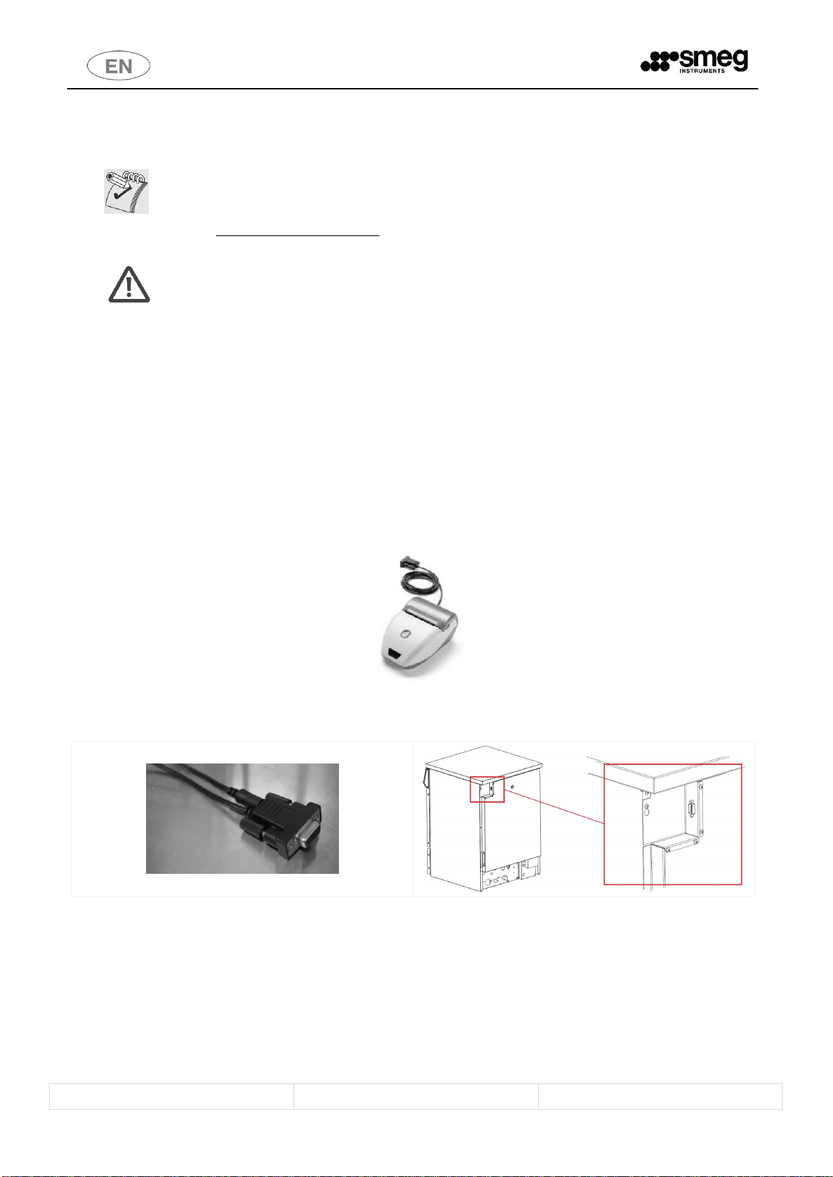
1.3.1 Smeg WD-PRINTE printer –GW2145, GW1160, GW4060 series................................................................ 8
1.3.2 Smeg WD-PRINT9 Printer –GW4190 Series .............................................................................................. 8
1.4 PERISTALTIC PUMP P3 (NOT INSTALLABLE ON GW2145) ................................................................................... 9
1.5 LIST OF MODELS................................................................................................................................................ 10
2KEY TO THE SYMBOLS USED IN THE MANUAL AND ON THE APPLIANCE .............................................................11
3GENERAL WARNINGS .........................................................................................................................................12
3.1 ACCESSING AND REUSING THE DEVICE AFTER AN INCOMPLETE CYCLE ........................................................... 13
3.2 DOOR OPENING ................................................................................................................................................ 14
3.3 MANUAL DOOR RELEASE PROCEDURE ............................................................................................................. 15
3.4 GW4190 OPENING THE DOOR OF THE SIDE CABINET - SERIES GW4190 ONLY ................................................ 15
4DESCRIPTION OF CONTROLS AND PROGRAMS...................................................................................................17
4.1 CONTROLS......................................................................................................................................................... 17
4.2 CONTROLS - DETAILED DESCRIPTION ............................................................................................................... 18
4.2.1 A0 PARAMETER DISPLAY........................................................................................................................... 19
4.3 INDICATOR LEDS - INTRODUCTION................................................................................................................... 20
4.4 INDICATOR LEDS - DETAILED EXPLANATION..................................................................................................... 21
4.5 SELECTING THE WASHING PROGRAMME ......................................................................................................... 23
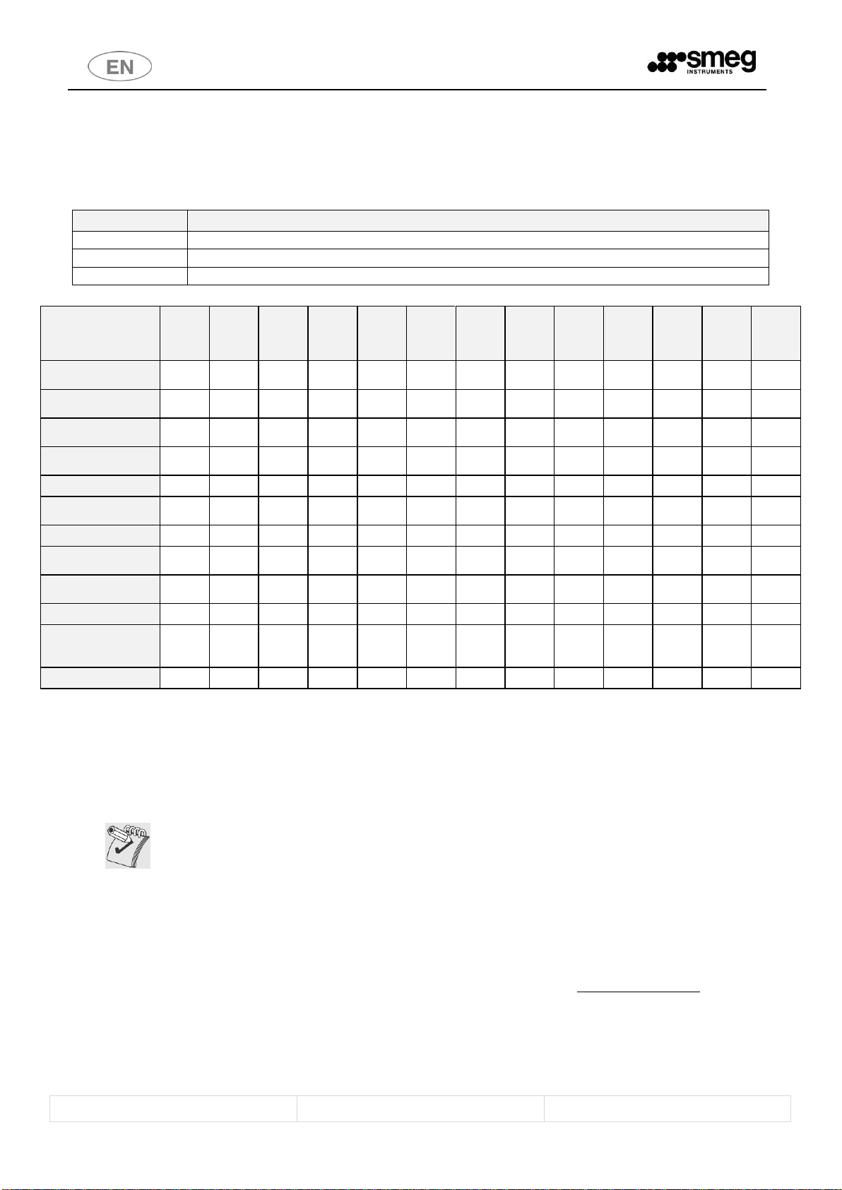
4.6 BRIEF TABLE OF THE PROGRAMS INSTALLED.................................................................................................... 25
4.6.1 RESINS - SOFTENER, REGENERATION AND WASHING PHASE ................................................................... 26
4.6.2 DRYING PHASE –Only for GW4060, GW4190 series ................................................................................ 26
4.6.3 CUSTOM PROGRAMS ................................................................................................................................ 28
4.7 A0 THERMAL DISINFECTION PARAMETER ........................................................................................................ 29
4.8 PREPARING THE LOAD FOR WASHING AND DISINFECTION.............................................................................. 30
4.9 END OF CYCLE ................................................................................................................................................... 31
4.10 INTERRUPTING A PROGRAM IN EXECUTION .................................................................................................... 32
4.11 PROGRAM SPECIAL OPTIONS............................................................................................................................ 33
4.11.1 DELAYED START - Setting the hours.......................................................................................................... 33
4.11.2 DELAYED START - Starting the program and display................................................................................. 33
4.11.3 TEMPORARY DISABLING OF DEMI WATER................................................................................................ 34
4.11.4 Deleting “Delayed start” - “No Demi” settings ......................................................................................... 35
4.12 RESET PROCEDURE............................................................................................................................................ 36
4.13 PRINTING THE CYCLE AND APPLIANCE PARAMETERS....................................................................................... 37
5SETUP MODE - “FUNCTIONS” .............................................................................................................................37
5.1 ACCESSING THE SETUP MODE / ENTERING THE PASSWORD ........................................................................... 38
5.2 ACCESS AND PARAMETER MODIFICATION ....................................................................................................... 39
5.3 “SET“ PARAMETERS .......................................................................................................................................... 41
5.3.1 APPLIANCE DATA STORAGE, OVERWRITING, “Set -b” .............................................................................. 44
5.4 “CLOC” – DATE AND TIME PARAMETERS.......................................................................................................... 46
5.5 SETTING THE “PrEn” “PROGRAM ENABLING” FUNCTION................................................................................. 46
6INSTALLATION INSTRUCTIONS ...........................................................................................................................49
6.1 USE OF THE WATER SOFTENER......................................................................................................................... 49
6.2 USING DETERGENT AND NEUTRALISING AGENT .............................................................................................. 50
6.2.1 LIQUID DETERGENT INTAKE SYSTEM ........................................................................................................ 50
6.2.2 DETERGENT LEVEL SENSORS - OPTIONAL ................................................................................................. 52

User Manual
GW2145 - GW1160 - GW4060 - GW4190
Page 5 - 86
6.3 USING THE DETERGENT DISPENSER –GW SERIES ONLY................................................................................... 53
6.4 RECOMMENDED DETERGENTS ......................................................................................................................... 54
7ALARMS AND WARNING MESSAGES ..................................................................................................................56
8CLEANING AND MAINTENANCE .........................................................................................................................64
8.1 CLEANING THE DEVICE AND ITS PARTS............................................................................................................. 64
8.1.1 GW2145 - filter elements.......................................................................................................................... 66
8.1.2 GW1160 - GW4060 –GW4190 - filter elements....................................................................................... 66
8.2 IF THE DEVICE IS TO BE OUT OF USE ................................................................................................................. 67
8.3 REUSING THE DEVICE AFTER A PERIOD OUT OF USE ........................................................................................ 67
8.4 TROUBLESHOOTING.......................................................................................................................................... 67
9ROUTINE INSPECTIONS AND MAINTENANCE .....................................................................................................69
9.1 DAILY................................................................................................................................................................. 69
9.2 WEEKLY ............................................................................................................................................................. 69
9.3 EVERY SIX MONTHS .......................................................................................................................................... 69
9.4 EVERY YEAR....................................................................................................................................................... 69
10 TECHNICAL DATA ...........................................................................................................................................70
11 PRODUCT DIMENSIONS - MEASUREMENTS IN MM ........................................................................................72
11.1 GW2145 ............................................................................................................................................................ 72
11.2 GW1160, GW4060 SERIES................................................................................................................................. 72
11.3 GW4190 SERIES................................................................................................................................................. 73
12 POSITIONING THE APPLIANCE ........................................................................................................................73
13 ELECTRICAL SYSTEM REQUIREMENTS.............................................................................................................77
13.1 GW2145 - POWER SUPPLY CABLE AND DISCONNECTION DEVICE.................................................................... 77
13.2 GW1160, GW4060, GW4190 - POWER SUPPLY CABLE AND DISCONNECTION DEVICE.................................... 77
14 WATER CONNECTION FITTINGS......................................................................................................................79
14.1 WATER INTAKE.................................................................................................................................................. 79
14.1.1 WATER INTAKE CONNECTION................................................................................................................... 79
14.1.2 WATER SUPPLY TAP POSITION.................................................................................................................. 79
14.1.3 WATER SUPPLY SYSTEM REQUIREMENTS................................................................................................. 80
14.1.4 PAD ACCESSORY FOR UNPRESSURISED DEMI WATER .............................................................................. 81
14.2 WATER DRAIN ................................................................................................................................................... 82
15 DATA CONNECTION........................................................................................................................................84

User Manual
GW2145 - GW1160 - GW4060 - GW4190
Page 6 - 86
1INTRODUCTION
GW2145, GW1160, GW4060, GW4190 –professional glassware washing machines, laboratory glassware washers
(GW –glassware washer).
Smeg GW1160, GW4060, GW4190 family products comply with all the prerequisites of the relevant safety regulations
and the standards in force for electrical equipment.
This manual describes products series:
•GW2145 Series, laboratory glassware washers, 45cm, without drying system.
•GW1160 Series, laboratory glassware washers, 60cm, without drying system.
•GW4060 Series: laboratory glassware washers, 60cm, equipped with forced air drying system.
•GW4190 series: laboratory glassware washers, 90cm, with forced-air drying system and side
cabinet to take detergent cans.
The diagrams and images contained in this document refer to GW4060 series. For the GW2145,
GW1160, GW4190 series the same considerations and procedures apply, unless otherwise specified.
The table below summarises the product’s main characteristics. (For a full list of models and their configurations refer
to the “LIST OF MODELS” point below).
GW –basic model
CONTROL
ELECTRONIC with MICROPROCESSOR
(with Time and Date functions)
DOOR OPENING
Automatic
DETERGENT DISPENSING
Powder detergent dispenser DD (integral in inner door)
and peristaltic pump P2
OPTIONAL DETERGENT DISPENSING
peristaltic pump P1
peristaltic pump P3 (not installable on GW2145)
CONTROL OF DETERGENT DISPENSING
Optional
DETERGENT CAN LEVEL CONTROL
Optional
TEMPERATURE CONTROL
Single Platinum PT probe (TL1)
STEAM CONDENSER
On special models with suffix “C”
(e.g. GW1160 Cxx, GW4060 Cxx, GW4190 Cxx)
DRYING SYSTEM
Yes, forced air (only on GW4060, GW4190 series)
ABSOLUTE DRYING FILTER
Optional (and only on GW4060, GW4190 series)
RAILS IN CHAMBER FOR TOP BASKET
Yes
WATER INTAKE CONNECTIONS
Mains and Demineralised
PRESET PROGRAMS
Specific LABORATORY programs, TOTAL OF 16
PROGRAMS of which 6 are CUSTOM (customisable using
SMEG TRACELOG software1. The software is not included
in the product’s basic outfit)
COMMUNICATION
RS232 serial (For PC or Printer)
1
The TRACELOG software enables the user to communicate with SMEG “WD” and “GW” instrument and glassware
washers.
Once the connection has been made, the user can:
- Keep a record of the disinfection cycles performed.
- Monitor the appliance’s status.
- Download new versions of the appliance’s software.
- Modify programs.
- Save the appliance parameter setup.

User Manual
GW2145 - GW1160 - GW4060 - GW4190
Page 7 - 86
1.1 GW FAMILY - INTENDED USE
Laboratory glassware washer.
The appliance is built to provide the following function:
Washing of laboratory glassware with chemical or thermal disinfection;
The appliance cannot be used to sterilize instruments or any other device.
Any use other than that described in this manual constitutes misuse.
SMEG declines all liability for uses other than those stated above.
SMEG declines all liability for any damage caused by the use of the appliance to wash glassware or
instruments not approved by their manufacturers for automatic decontamination by means of
thermal disinfection.
The appliance may only be used by specifically trained staff. Smeg will train the staff assigned to
use the appliance at the time of installation.
Smeg declines all liability in the event of malfunctions or accidents caused by use of the appliance
by untrained staff.
The training of the staff responsible includes specific information on the possible risks involved in
the use of the appliance, and training in the safest possible way of carrying out the operating
procedures.
The Smeg installation engineer is also responsible for notifying the responsible authority of the
USER and SUPERUSER passwords to access the setup parameters. The responsible authority must
keep these passwords in a safe place.
It is the duty of the appliance’s RESPONSIBLE AUTHORITY to ensure that those using the
equipment have been suitably trained in its operation, its safe use and routine checks, and that
this training is suitably maintained.
Staff training should be checked regularly.
The installation engineer is responsible for ensuring that it operates correctly after commissioning.
Safety information supplied in compliance with 5.4.101.1 IEC61010-2-040:2005
Instrument manufacturers’ instructions should always be followed when choosing the most
appropriate disinfection treatment.
In particular, it is important to check the compatibility of the load for treatment with the specific
washing cycle chosen, in terms of the maximum temperatures reached and the chemicals used.
Information supplied in compliance with point 5.4.4.r IEC61010-2-040:2005.
1.2 DEFINTITION: “RESPONSIBLE AUTHORITY” IN RELATION TO THE DEVICE
Responsible authority: “Person or group responsible for the use and ordinary maintenance of the unit and for operator
training.
Definition taken from point 3.5.13 of the IEC61010-1:2001 standard.
The responsible authority should be clearly identified within the facility where the appliance is used, (for example by
recording the relative names and responsibilities on corporate forms).

User Manual
GW2145 - GW1160 - GW4060 - GW4190
Page 8 - 86
1.3 WASHING TROLLEYS AND ACCESSORIES
N.B: the device is supplied without the washing trolleys and instrument holder baskets.
Contact Smeg for details of the range of racks and baskets best suited to your washing
requirements.
Visit www.smeg-instruments.com for information about the standard range of products available.
Any accessories may not be installed on the appliance by the user; this must be done by Smeg
authorised technical staff.
Any components must always be replaced with genuine Smeg spare parts.
1.3.1 Smeg WD-PRINTE printer –GW2145, GW1160, GW4060 series
The appliance’s RS232 port can be used to connect the external Smeg WD-PRINTE printer, supplied with its own
power transformer.
This accessory should be used only with thermal paper, 57.5mm ± 1mm, recommended weight 55 g/m2.
To operate this accessory, simply connect the transformer to the power socket and connect the RS232 port to the
RS232 socket on the rear of the glassware washer.
Refer to the accessory’s manual for detailed instructions.
fig. 1 –Smeg desktop printer.
fig. 2 –RS232 cable supplied with the printer and position of the RS232 socket on the device.
1.3.2 Smeg WD-PRINT9 Printer –GW4190 Series
The Smeg “WD-PRINT9” is a panel printer that can be installed inside the side cabinet on GW4190 series devices.

User Manual
GW2145 - GW1160 - GW4060 - GW4190
Page 9 - 86
fig. 3 –WD-PRINT9 accessory.
1.4 PERISTALTIC PUMP P3 (NOT INSTALLABLE ON GW2145)
Peristaltic pump P3 is always optional: contact Smeg for advice about the model best suited to your needs.
Note for GW4190 series: the device’s cabinet is designed to take two 5 litre cans of Smeg detergent.
To take a third detergent can, for use in combination with P3, the cabinet must be fitted with the
Smeg “TANKBSK” (Tank Basket) accessory.

User Manual
GW2145 - GW1160 - GW4060 - GW4190
Page 10 - 86
1.5 LIST OF MODELS
GW1160, GW4060 model configuration chart.
Symbol used:
SYMBOL
MEANING
feature present
optional accessory, installable on the model.
-
feature not present and not installable on the model.
GW MODELS
Features
GW2145
GW1160
GW4060
GW4190
GW1160S
GW4060S
GW4190S
GW1160SC
GW4060SC
GW4190SC
GW1160C
GW4060C
GW4190C
DD - Powder detergent
dispenser in inner door
-
-
-
-
-
-
P1 - Peristaltic
detergent pump
P2 - Neutralising agent
peristaltic pump
P3 - Optional
peristaltic pump
-
Drying System
-
-
-
-
-
Absolute filter (dryer
air)
-
-
-
-
-
Steam condenser
-
-
-
-
-
-
-
Control of detergent
dispensing
Detergent can level
control
Acquastop
-
Side cabinet to
accommodate 3
detergent cans
-
-
-
-
-
-
-
-
-
Electrical main switch
-
-
-
-
-
-
-
-
-
ELECTRICAL CONFIGURATION
A number of different electrical connection options are available for each 60cm and 90cm model
referred to in the table.
The names of the models have different suffixes to identify the power supply rating. Example:
- “GW4060-1”, ”GW1160-1” and “GW4190-1” refer to 230V single-phase models: “ 1N~ ”
- “GW4060-3”, “GW1160-3” and “GW4190-3” refer to three-phase models, 230V between phases, without
neutral: “ 3~ ”
- “GW4060”, “GW1160” and “GW4190”. If the model does not have a suffix it will be three-phase, with
neutral, 400V between phases: “ 3N~ ”.
- “GW4060U”, “GW1160U” and “GW4190U”. The “U” suffix refers to “North American models”, convertible
208V models: 208V 3~ 60Hz * / 208 V ~ 60Hz (* default connection).
For the 45 cm model: GW2145, only the single-phase model is available for 230V ~ 50Hz electrical
connection with Schuko plug
Contact Smeg for advice about the model best suited to your needs instruments@smeg.it

User Manual
GW2145 - GW1160 - GW4060 - GW4190
Page 11 - 86
2KEY TO THE SYMBOLS USED IN THE MANUAL AND ON THE APPLIANCE
The following is the key to the symbols used on the appliance and in this manual, as required by point 5.4.4.e of
IEC61010-2-040:2005.
Read with particular attention.
(Symbol which appears beside particularly important instructions or warnings).
Warning, danger: refer to the manual.
(The symbol appears on the appliance’s technical dataplate to emphasise that staff must read the
manual before using the device. The symbol appears in the manual next to safety instructions)
Warning, hot surface.
(the symbol is affixed to the appliance close to parts which may heat to high temperatures and
constitute a burn hazard - do not touch parts near this symbol. The symbol appears in the manual
to emphasise safety instructions relating to the burn hazard).
Warning, electric shock hazard.
(The symbol is affixed close to live parts - the device’s power supply must be disconnected before
doing any work on these parts. Never touch live parts unless the electricity supply is disconnected).
Transport and unpacking precautions.
Flammability hazard.
Biohazard.
At the end of its working life, the product must be consigned to a disposal plant for recovery and
recycling in accordance with the relevant legislation in the country of installation. Contact the
specialist disposal consortia. This appliance is marked according to the European Directive
2002/96/EC on waste electrical and electronic equipment (WEEE). By ensuring this product is
disposed of correctly, you will help prevent potential negative consequences for the
environment and human health, which could otherwise be caused by inappropriate waste handling
of this product.
CE marking; the manufacturer guarantees compliance with the EU directives applicable to the
product. This symbol appears on the machine’s technical data label and in this manual.

User Manual
GW2145 - GW1160 - GW4060 - GW4190
Page 12 - 86
3GENERAL WARNINGS
Leaning or sitting on the open door of the device might cause it to tip over, putting people in
danger. The door is not designed primarily to support loads.
The maximum weight which can be loaded on the door, including the weight of the instrument
trolley, must never exceed
GW1160, GW4060, GW4190: 37kg
GW2145: 18kg
- if the weight of the instrument trolley and baskets is excluded, the maximum load must never
exceed:
GW1160, GW4060, GW4190: 23kg.
GW2145: 15Kg
For optimal DRYING, the load for processing must never exceed 15 kg. (only for GW4060,
GW4190 Series).
With use of the glassware washer, localised or general discolouring of the heating element may
occur. This is normal since it is due to the operating mode and does not reduce the appliance’s
effectiveness.
In the event of malfunction, disconnect the appliance from the electricity supply and turn off the
water tap. Then contact your nearest authorised Service Centre.
Open the door carefully, first waiting for the wash cycle to end.
The appliance has an automatic door opening system; do not force the door open while a program
is in progress.
The appliance must only be used by staff suitably trained in its operation.
The chamber of the appliance is not designed for users to climb into it. The user must never climb
into the chamber; this might put his safety at risk (ref. 7.102 IEC61010-2-040:2005).
Do not place flammable substances inside the device. Do not use flammable detergents.
Never place alcohol or solvents such as turpentine, which might cause an explosion, inside the
appliance. Do not place materials dirty with ash, wax or paint inside the appliance.
DEMI WATER ABSENCE
If demineralised water is not available, the user is responsible for ensuring that the quality of the
water supplied to the medical device does not cause mineral salts or other substances to be
deposited on the treated instruments, rendering their subsequent use unsafe.
Never touch the heating element immediately after the end of a wash programme.
Do not touch any residual liquids left inside the washing chamber; scalding hazard (ref. 7.102.c
IEC61010-2-040:2005).
When moving the appliance around, a forklift truck or pallet truck must be used.
Before leaving the factory, the base of the appliance is secured to a pallet, which is used for lifting
and transporting it.
Do not use appliances which have been damaged in transit!
If in doubt, contact your dealer.
Once decommissioned, the appliance must be rendered unusable. Cut the power supply cable
after removing the plug / disconnecting the cable from the power socket.

User Manual
GW2145 - GW1160 - GW4060 - GW4190
Page 13 - 86
3.1 ACCESSING AND REUSING THE DEVICE AFTER AN INCOMPLETE CYCLE
The instructions relating to the device’s safety in the event of an incomplete operating cycle are provided in
compliance with points 5.4.4.g and 13.1.102 of IEC61010-2-040:2005.
WARNING
Warning applicable if the device is used for processing of contaminated materials.
If a disinfection cycle is interrupted (by the user or due to an alarm generated by the appliance
itself): take care when handling the elements and the load in general in the washing chamber.
The load and the internal parts of the appliance might be biologically contaminated/infected.
Before handling tools or performing any maintenance: Perform a complete disinfection cycle or,
if you cannot perform a complete Thermo-disinfection cycle, handle tools with caution (using
protection devices required for the handling of infected instruments, eg. gloves, lab coat).
DANGER, HOT SURFACES
The appliance performs a thermal disinfection cycle using water at high temperatures (up to 93°C)
and detergents. If, in the event of a failure, there is water in the chamber when the door is open:
avoid contact with the skin, burning hazard and risk of irritation due to the toxicity of the
chemicals used.
Never touch the heating elements inside the chamber.
Contact Smeg authorised technical staff in the event of a failure.
fig. 4 –View of inside of chamber, detail of heating elements.
Do not touch
the heating
elements

User Manual
GW2145 - GW1160 - GW4060 - GW4190
Page 14 - 86
3.2 DOOR OPENING
The following is a brief preview of the procedure for opening the door of the device for easier access to the chamber.
The points which follow provide a complete description of all the controls.
The appliance is equipped with an automatic door locking system.
Do not force it open; proceed as follows:
Connect the appliance to the electricity supply.
For GW4190 series only: open the hatch of the side cabinet and turn the main switch on.
Hold down the button with the On/Off symbol for 2 seconds to switch the appliance on.
Press the Door opening button: the appliance gives a beep when it receives the signal. Release the button
and the door will open automatically after a few moments.
BUTTONS TO BE PRESSED TO OPEN THE DOOR
On/Off
Door opening
fig. 5 –Selecting automatic door opening
To open the door without connecting the appliance to the electricity supply (useful for emergencies or in case of
power blackouts), the manual release system has to be used (see next point).

User Manual
GW2145 - GW1160 - GW4060 - GW4190
Page 15 - 86
3.3 MANUAL DOOR RELEASE PROCEDURE
If necessary, due to a malfunction or power blackout, the appliance can be opened manually by releasing the lock
using a screwdriver with stem Ø4mm; be gentle, taking care not to damage the device.
1. This procedure is only possible with the appliance in standby status, with no cycle running.
2. Warning: before opening the appliance manually, disconnect it from the electricity supply.
3. Insert a screwdriver or a rod 4 mm in diameter into the hole in the bottom of the centre of the front panel.
4. Push the pin upward until the lock is released.
fig. 6 –Diagram showing how to release the lock by hand in any emergency.
3.4 GW4190 OPENING THE DOOR OF THE SIDE CABINET - SERIES GW4190 ONLY
GW4190 series models have a side cabinet with a hatch which opens like a drawer. Once the hatch is open, users have
full access to the components inside:
Main switch (circuit-breaker),
Panel printer (if installed),
Detergent cans.
To open the cabinet hatch, simply pull it towards you using the stainless steel handle provided.
The following are located above the panel that carries the master switch and printer:
RS232 port: for data transmission –connection by means of Smeg TRACELOG software.
“Data output” switch: used to activate the panel printer or data transmission on the RS232 port. These two
devices can never operate simultaneously. The data output switch activates the RS-232 port when turned to
“I” or the printer when turned to “II”.

User Manual
GW2145 - GW1160 - GW4060 - GW4190
Page 16 - 86
fig. 6 –Opening the GW4190 side cabinet hatch.
fig. 6 –GW4190: Once the side cabinet hatch is open, the user has access to the device’s master switch (and the printer, if installed).
fig. 6 –GW4190: the RS232 data port and the data output switch (which directs data either to the transmission port or to the printer) are located
above the master switch panel.
RS232 data
port
data output
switch

User Manual
GW2145 - GW1160 - GW4060 - GW4190
Page 17 - 86
4DESCRIPTION OF CONTROLS AND PROGRAMS
4.1 CONTROLS
All the device’s control and monitoring devices are placed together on the front panel.
GW4060, GW4190 CONTROL PANEL
GW2145, GW1160 CONTROL PANEL
fig. 7 –Control panel. The display and indicator LEDs are in the middle and the control buttons at the sides and bottom.
CONTROL PANEL SYMBOLS
SYMBOL
MEANING
SYMBOL
MEANING
On/Off
Functions
Drying Decrease
(only on GW4060, GW4190 series)
Drying Increase
(only on GW4060, GW4190 series)
Start / Stop
Door opening
Selection
Selection
In the figures mentioned in this document, we use only the GW4060 front panel layout. The same
considerations and procedures apply to the GW1160, GW4190 models, unless otherwise specified.

User Manual
GW2145 - GW1160 - GW4060 - GW4190
Page 18 - 86
4.2 CONTROLS - DETAILED DESCRIPTION
BUTTONS
DESCRIPTION
On/Off
The button is operational with the door opened or closed.
The button turns the device’s interface on and off, allowing its use. Hold it down for 2
seconds for both switch-on and switch-off.
Once the appliance has been switched on, the code of the selected program appears on
the display (e.g. “Pr 03”).
When the interface is switched off, the display shows a flashing “OFF” message.
When the door is open, the display shows 4 horizontal dashes and none of the other
interface buttons are active.
The device is still powered up even when the interface is off.
-
Drying +/- (only on GW4060, GW4190 series)
The buttons increase/decrease the intensity (and duration) of the drying phase.
Holding down the “Drying–” button selects a separate drying program; the display shows
the message “Pdry”.
If the cycle set has a drying phase, these buttons are enabled and the drying LED
illuminates.
If the cycle set does not include a drying phase, the buttons are not enabled and the
drying LED remains off.
These are “first touch” buttons; there is no need to hold them down.
The drying duration set is displayed as follows:
- 3 horizontal bars on the display; maximum time setting, default time
- 2 horizontal bars, medium duration
- 1 horizontal bar, short duration
Start/Stop
This button starts the selected cycle or interrupts a cycle in progress. It must be held
down for 2 seconds.
Two beeps sound when a cycle is started or stopped.
The button is also used (again holding it down) to confirm the value of an appliance
parameter during modification.
Functions
Hold down: access to the appliance setup parameters, password required. Refer to the
SETUP MODE - “FUNCTIONS” section for a detailed explanation.
Short press: whenever the Functions button is pressed,
the display screen changes; the various screens show the parameters of the cycle
selected in combination with the LED which explains their meaning.
For a full understanding of the values shown on the display, note that they depend on the
appliance’s status:
1. Appliance in standby
2. Washing cycle running
LED
ON DISPLAY
Meaning of LED on
1 : 16
With appliance in standby
The value is the nominal duration of the cycle. The time LED
also illuminates. The duration is guideline; it applies in test
conditions and with correct electrical connection.
With cycle running
Time left to end of current cycle
-- : 90
With appliance in standby
Maximum temperature reached in the cycle set
With cycle running
- During washing: Tank temperature
- During drying: Inlet air temperature
(function introduced from firmware version 4.6.xx.yy).

User Manual
GW2145 - GW1160 - GW4060 - GW4190
Page 19 - 86
BUTTONS
DESCRIPTION
600
With appliance in standby
A0 value associated to the selected cycle, if the cycle includes a
thermal disinfection phase.
With cycle running
Display function which starts from the thermal disinfection
phase: displays the A0 value reached.
The value reached during the thermal disinfection phase is
displayed during the phases which follow.
[The parameter is displayed on two consecutive display screens
from firmware version 1.11.0.33. The value in thousands is
indicated by the suffix "t", in units with the suffix "u"]
-
F5
With appliance in standby
Number of phases in the program
With cycle running
Current phase
N.B.: Washing cycles always start with a short draining phase to
bring the device to the standard starting condition: this phase is
called “phase 0”.
-
PR 03
If the user does not give any commands for 5 seconds, the
display shows the program selected.
Door opening
The door is opened automatically by means of an electric lock; opening is only permitted
in conditions of safety for the user.
The user simply presses the button; there is no need to hold it down.
The button also provides an “Escape” function; it is pressed to quit the procedure for
displaying or modifying an appliance parameter. In this case, it has to be held down (2
seconds).
-
Selection
Program selection buttons. The letter “P” and the name of the selected program appear
on the display.
These buttons can be used to increase or decrease the current value during modification
of an appliance parameter.
4.2.1 A0 PARAMETER DISPLAY
The parameter is displayed on two consecutive display screens from firmware version 1.11.0.33.
The A0 parameter can reach high values (eg typical A0 = 12000) and will appear on two consecutive screens;
thousands display screen (t-Thousands) and units screen (u-units), the value in thousands is indicated by the suffix "t"
units with the suffix" u ". The transition from one screen to the next occurs automatically after 3 seconds or by short
press of the "Functions" key.
fig. 8 –The A0 value is displayed split into thousands (t) and units (u)

User Manual
GW2145 - GW1160 - GW4060 - GW4190
Page 20 - 86
4.3 INDICATOR LEDS - INTRODUCTION
fig. 9 –In the front panel display area: digit area in the centre with indicator LEDs around the perimeter
LED SYMBOLS
SYMBOL
MEANING
SYMBOL
MEANING
No detergent
A0, thermal disinfection
Maintenance: filter
replacement
(Only for GW4060, GW4190)
Temperature
Appliance maintenance
Time: time left on display
Lack of salt
Thermal disinfection,
identifies cycles with
thermal disinfection
Alarm
Drying
(Only for GW4060,
GW4190)
Other manuals for GW2145
1
This manual suits for next models
4
Table of contents
Other Smeg Washer manuals