Smitec ICOS-PS 3160 Series User manual

Power supply ICOS-PS 3160 series Installation, use and maintenance manual - EN
Ver. 1.05 1
Smitec S.p.A., viale Vittorio Veneto 4, 24016 San Pellegrino Terme (BG), Italy, www.smitec.it
Installation, use and maintenance manual
POWER SUPPLY UNITS
ICOS-PS 3160 SERIES
BEFORE PUTTING INTO SERVICE THE POWER SUPPLY UNITS OF THE ICOS-PS
3160 SERIES, CAREFULLY READ THIS MANUAL AND FOLLOW ALL INSTRUCTIONS,
IN ORDER TO ENSURE MAXIMUM SAFETY
The technical data and the drawings in this manual might have been modified later; always
refer to the latest version.

Power supply ICOS-PS 3160 series Installation, use and maintenance manual - EN
Ver. 1.05 2
Summary
1 Preface ....................................................................................................................................................... 4
2 General warnings ...................................................................................................................................... 5
3 Safety instructions .................................................................................................................................... 7
3.1 General information ............................................................................................................................ 7
3.2 Precautions during handling and assembly ........................................................................................ 7
3.3 Precautions against the risk of Electric Shock .................................................................................... 8
3.4 Precautions against contact with hot parts ......................................................................................... 8
3.5 Residual risks ...................................................................................................................................... 9
4 Technical data ......................................................................................................................................... 10
4.1 Environmental specifications ............................................................................................................ 10
4.2 Power supply .................................................................................................................................... 11
4.3 DC output .......................................................................................................................................... 11
4.4 Dynamic brake output ....................................................................................................................... 11
4.5 Digital I/O .......................................................................................................................................... 12
4.6 Order codes ...................................................................................................................................... 12
4.7 Accessories ....................................................................................................................................... 12
4.8 Mechanical specifications ................................................................................................................. 13
4.8.1 Weight ....................................................................................................................................... 13
4.8.2 Overall dimensions ................................................................................................................... 13
5 Installation and putting into service ...................................................................................................... 14
5.1 Preliminary operations ...................................................................................................................... 14
5.2 Installation mode ............................................................................................................................... 15
5.3 Positioning and fastening .................................................................................................................. 16
5.4 Connections ...................................................................................................................................... 18
5.4.1 Upper view ................................................................................................................................ 18
5.4.2 Front view ................................................................................................................................. 19
5.4.3 Bottom view .............................................................................................................................. 20
5.5 Mains power supply - J1 ................................................................................................................... 21
5.5.1 Connection schematic ............................................................................................................... 24
5.5.2 Conductors and protective devices ........................................................................................... 26
5.5.2.1 Protection for UL applications ........................................................................................... 26
5.5.2.2 Protection for other applications ....................................................................................... 26
5.5.3 EMI filtering ............................................................................................................................... 27
5.6 Braking/discharge resistor output - J2 .............................................................................................. 29
5.7 DC BUS output - J3 .......................................................................................................................... 31
5.8 Auxiliary power and I/Os - CTR ........................................................................................................ 34
5.8.1 Power supply setting ................................................................................................................. 35
5.8.2 Interface I/Os ............................................................................................................................ 36
5.9 Reactor - J4 ...................................................................................................................................... 38
5.10 Status LEDs .................................................................................................................................... 44
6 Operation and diagnostics ..................................................................................................................... 46
6.1 General status ................................................................................................................................... 46
6.2 Capacitors charging .......................................................................................................................... 47
6.3 Anomalies during the charging phase ............................................................................................... 48
6.4 Working operation and possible anomalies ...................................................................................... 49
6.5 Dynamic braking ............................................................................................................................... 53
6.6 Missing phase ................................................................................................................................... 54
6.7 Automatic capacity discharge operation (ICOS-PS 3162 only) ........................................................ 54
6.8 Digital input: RESET ......................................................................................................................... 55
7 Storage ..................................................................................................................................................... 56
8 Maintenance ............................................................................................................................................ 57
8.1 Replacement of the charging resistor ............................................................................................... 58

Power supply ICOS-PS 3160 series Installation, use and maintenance manual - EN
Ver. 1.05 3
9 Decommissioning and disposal ............................................................................................................ 59
10 Analytical index ..................................................................................................................................... 60

Power supply ICOS-PS 3160 series Installation, use and maintenance manual - EN
Ver. 1.05 4
1 Preface
This manual provides all necessary information for the installation, use and maintenance of the power supply
units ICOS-PS 3160.
The instructions included in this manual are addressed to the following professionals:
The present instructions must be made available to all the above individuals.
User User is a person, a company or an institution that buys the equipment and
uses it for the purposes it was designed for.
User/operator User or operator is a person authorized by the user to operate on the equip-
ment.
Specialized personnel It refers to all persons with specific competence, able to recognize and avoid
the dangers deriving from the use of the equipment.
Power supply ICOS-PS 3160 series Installation, use and maintenance manual - EN
Ver. 1.05 5
2 General warnings
These assembly instructions are an integral part of the equipment, and must be kept for future reference until
it decommissioned.
The user should be informed that the present instructions reflect the state of the art at the moment when the
equipment was sold; they will remain fully acceptable despite subsequent upgrades based on new technical
update.
In order to make the manual consultation easier, the following symbols have been adopted:
DO NOT USE THE EQUIPMENT, NOR MAKE ANY INTERVENTION BEFORE INTE-
GRALLY READING AND UNDERSTANDING THIS MANUAL.
IN PARTICULAR, ADOPT ALL SAFETY PRECAUTIONS AND PRESCRIPTIONS INDICATED IN THIS
MANUAL.
THE EQUIPMENT MUST NOT BE USED FOR PURPOSES DIFFERENT THAN THE ONES DESCRIBED
IN THIS MANUAL; SMITEC S.p.A. SHALL NOT BE HELD RESPONSIBLE FOR ANY DAMAGES, IN-
CONVENIENCES OR ACCIDENTS DUE TO THE NON-COMPLIANCE WITH THESE PRESCRIPTIONS.
Indication of “PROHIBITED ACTION”.
The symbol “DANGER” is used when non-compliance with the prescriptions or misuse may
cause serious injuries.
The symbol “DANGER FROM HOT SURFACES” is used when non-compliance with the
prescriptions or misuse may cause serious injuries.
The symbol “DANGER FROM ELECTRICAL SHOCK” is used when non-compliance with
the prescriptions or misuse may cause serious injuries.

Power supply ICOS-PS 3160 series Installation, use and maintenance manual - EN
Ver. 1.05 6
The safety requirements are intended to define a series of behaviors and obligations to be followed in carrying
out the activities listed below.
These prescriptions constitute the prescribed method of operating the device, in a way that is safe for person-
nel, equipments and environment.
The symbol “USE OF INDIVIDUAL PROTECTIONS” means that protective gloves must be
worn.
The symbol “USE OF INDIVIDUAL PROTECTIONS” means that protective glasses must be
worn.
Indication of “INFORMATION OF PARTICULAR RELEVANCE”.
Power supply ICOS-PS 3160 series Installation, use and maintenance manual - EN
Ver. 1.05 7
3 Safety instructions
3.1 General information
3.2 Precautions during handling and assembly
Do not install or use the equipment before integrally reading and understanding this manual.
In case of difficulties of interpretation, contact SMITEC technical service.
It is absolutely forbidden to use the equipment for different purposes than the ones de-
scribed in this manual. The technical data and the drawings in this manual might have been
modified later; always refer to the latest version. All upgrades can be requested to SMITEC
S.p.A. directly.
Make sure that the personnel is qualified and adequately informed about the risks he may
run and how to avoid them.
Use adequate tools during the assembly, in order to avoid crushing or abrasions.
Metal components and sharp surfaces may cause cuts and tears. In case of contact, be very
careful and wear the personal protection equipment.

Power supply ICOS-PS 3160 series Installation, use and maintenance manual - EN
Ver. 1.05 8
3.3 Precautions against the risk of Electric Shock
3.4 Precautions against contact with hot parts
WARNING
AVERTISSEMENT
All connectors on the equipment except for the interface connector (CTR) are potentially
connected to dangerous voltages. Pay attention, to avoid danger of Electric Shock.
During all phases of installation and maintenance of the equipment, disconnect it safely from
the power supply network. Electric Shock risk.
Some components of the apparatus (for example: the aluminium heatsink) are made of con-
ductive materials. They must be connected securely to the protective conductor (PE/
Ground) using the appropriate terminals, to avoid risk of Electric Shock.
Internally, the apparatus mounts the capacitors that retain a dangerous potential for at least
10 minutes after switching off. Before any operation, make sure that it has been disconnect-
ed from the network for at least 10 minutes.
Never use the device partially or totally disassembled. Danger of Electric Shock and / or
damage to persons and property.
The heat sink of this device may become hot during its service: Hot Surface, Risk of Burn.
Le dissipateur thermique de cet appareil peut chauffer pendant son utilisation: Surface
Chaude, Risque de Brûlure.
Power supply ICOS-PS 3160 series Installation, use and maintenance manual - EN
Ver. 1.05 9
3.5 Residual risks
By using the power supply in the construction of a machine, the manufacturer must take all
precautions to avoid the operator's contact with the hot parts, to avoid the risk of burns.
The braking resistor can reach high temperatures; implement all the precautions necessary
to prevent the danger of burns.
The apparatus generates an electromagnetic field during operation. Danger for people with
pacemakers, metal prostheses or hearing aids.
Power supply ICOS-PS 3160 series Installation, use and maintenance manual - EN
Ver. 1.05 10
4 Technical data
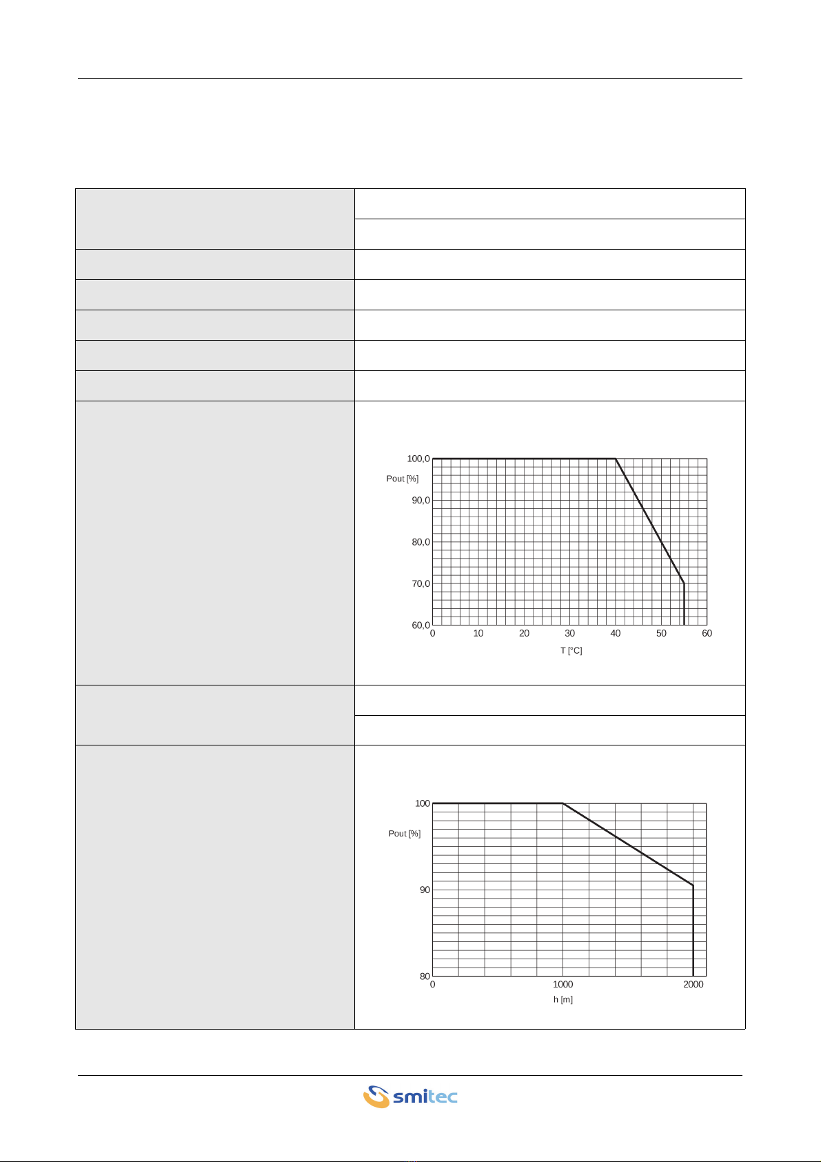
4.1 Environmental specifications
Operating temperature
(Maximum surrounding air temperature)
0° ÷ +45°C with full-load operation
0° ÷ +55°C with current derating
Environment of use Use in Pollution degree 2 Environment
Degree of protection IP20
Air humidity during operation 5 ÷ 85% non condensing
Storage temperature -25°C ÷ +55°C
Air humidity during storage 5 ÷ 95%
Output current derating depending on
the environmental temperature
Maximum altitude
1000 m a.s.l., at rated output current
2000 m a.s.l., with current derating
Output current derating depending on
the altitude

Power supply ICOS-PS 3160 series Installation, use and maintenance manual - EN
Ver. 1.05 11
4.2 Power supply
4.3 DC output
4.4 Dynamic brake output
Mains voltage 230V AC ±15% 50/60 Hz
Type of power supply Single-phase or three-phase
Maximum short-circuit current 5 kA at the installation point
Mains power supply absorption
28.2A RMS (single-phase power supply)
26.5A RMS (three-phase power supply)
Auxiliary mains voltage 24V DC -15 ÷ +20%
Auxiliary mains power supply max. ab-
sorption 30mA
The input current strictly depends on the line impedance; the values refer to sinusoidal
mains with generator impedance equal to zero. In real cases, the input current may undergo
a reduction up to 30%.
Rated voltage 325V DC not stabilized
Max output current
16.0A (three-phase power supply)
9.0A (single-phase power supply)
Max output power
5.0 kW (three-phase power supply)
2.8 kW (single-phase power supply)
Braking resistor value range 20 Ω min.
Max braking power About 10 kW
Average braking power 5 kW

Power supply ICOS-PS 3160 series Installation, use and maintenance manual - EN
Ver. 1.05 12
4.5 Digital I/O
4.6 Order codes
4.7 Accessories
The power supply units of the ICOS-PS 3160 series are supplied with a complete series of detachable connec-
tors for power supply and I/Os connection. The connectors can also be ordered separately, like other not in-
cluded accessories. Here are the order codes:
Reset 24V digital input. Device reset.
Power good 24V digital output. It indicates the device status.
Alarm 24V digital output. It indicates alarm conditions of the device.
1PH/3PH setting Jumper inputs. Single-phase or three-phase operation setting.
Order codes Model Description
KZ010451 ICOS-PS 3161 325VDC power supply unit for servodrives.
KZ010628 ICOS-PS 3162 325VDC power supply unit for servodrives with
automatic discharge
Order code Item
KF101042 230 VAC power connector
KF101043 Brake resistor connector
KG020099 DC BUS output connector with “L+ L-” label
KG020100 Reactor connector with “X X” label
KG020102 Auxiliary power supply and I/O connector with label
KG020098 39Ω capacitors charging resistor, wound on mica, complete with support
Power supply ICOS-PS 3160 series Installation, use and maintenance manual - EN
Ver. 1.05 13
4.8 Mechanical specifications
4.8.1 Weight
The following table indicates the weight of the different models, including all detachable connectors:
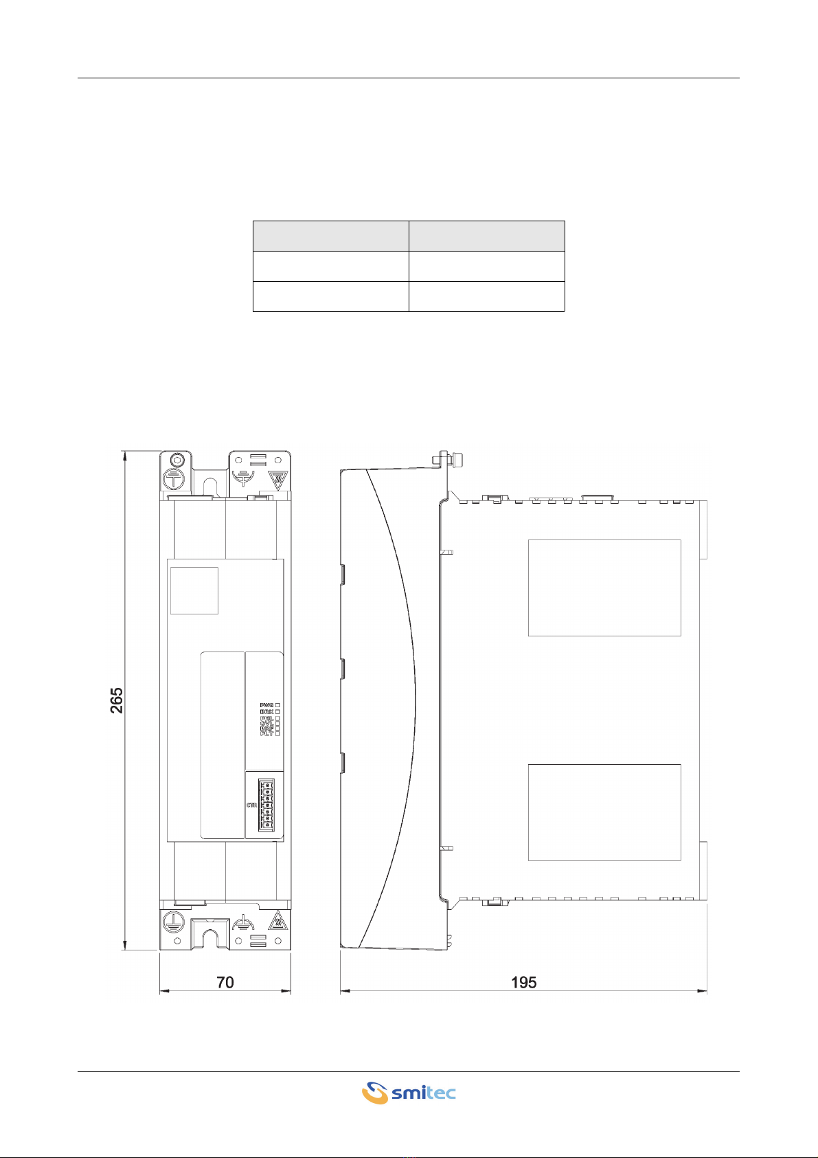
4.8.2 Overall dimensions
External size of the device only, without detachable connectors.
Type Weight (kg)
KZ010451 2.2
KZ010628 2.2
Power supply ICOS-PS 3160 series Installation, use and maintenance manual - EN
Ver. 1.05 14
5 Installation and putting into service
5.1 Preliminary operations
Before putting into service the device, make the following checks:
• check the perfect integrity of the device and its components;
• make sure that all manuals necessary for installation are available;
• read and understand this manual integrally.
WARNING
AVERTISSEMENT
WARNING
AVERTISSEMENT
Metal parts and all “live” parts can under certain conditions cause cuts and tears. Pay par-
ticular attention in case of contact and use suitable personal protective equipment (PPE).
Les pièces métalliques et toutes les pièces sous tension peuvent, dans certaines condi-
tions, provoquer des coupures et des déchirures. Portez une attention particulière en cas
de contact et utilisez un équipement de protection individuelle (EPI) approprié.
Use adequate tools during the assembly, in order to avoid crushing or abrasions.
Lors du montage de l’appareil, utilisez des outils appropriés pour éviter tout risque de bles-
sure, d’écrasement, d’abrasion, etc.

Power supply ICOS-PS 3160 series Installation, use and maintenance manual - EN
Ver. 1.05 15
5.2 Installation mode
During the installation of the device, the upper and lower part must have a free space of at least 100 mm com-
pared to other components or to the walls of the electrical panel, while other components can be placed along-
side the ICOS-PS 3160 power supply without leaving any space.
100 mm
100 mm
Electrical panel
No space constraints
No space constraints

Power supply ICOS-PS 3160 series Installation, use and maintenance manual - EN
Ver. 1.05 16
5.3 Positioning and fastening
The device must be fastened to a vertical wall inside the electrical panel; the heat sink is provided with two slots
for screws having metric ISO thread M5.
Tighten the screws (the tightening torque depends on the holding panel and on the type of screw); it is recom-
mended to use locking washers (Grover or Belleville) or apply a medium strength thread locking compound
(Loctite type 243 or equivalent) on the bolt shank.
The power supply units ICOS-PS 3160 are designed to operate in enclosed electrical oper-
ating areas (according to IEC 61800-5-1:2009-04); “at sight” installation outside an electrical
panel is not allowed.

Power supply ICOS-PS 3160 series Installation, use and maintenance manual - EN
Ver. 1.05 17
The picture here below shows the position of the holes to be arranged in the holding panel.
Power supply ICOS-PS 3160 series Installation, use and maintenance manual - EN
Ver. 1.05 18
5.4 Connections
Electrical connections are ensured by detachable connectors, except for the connection PE (Ground), which
must be connected by means of an eyelet crimp terminal and a suited fastening screw.
The following paragraphs describe the connectors position.
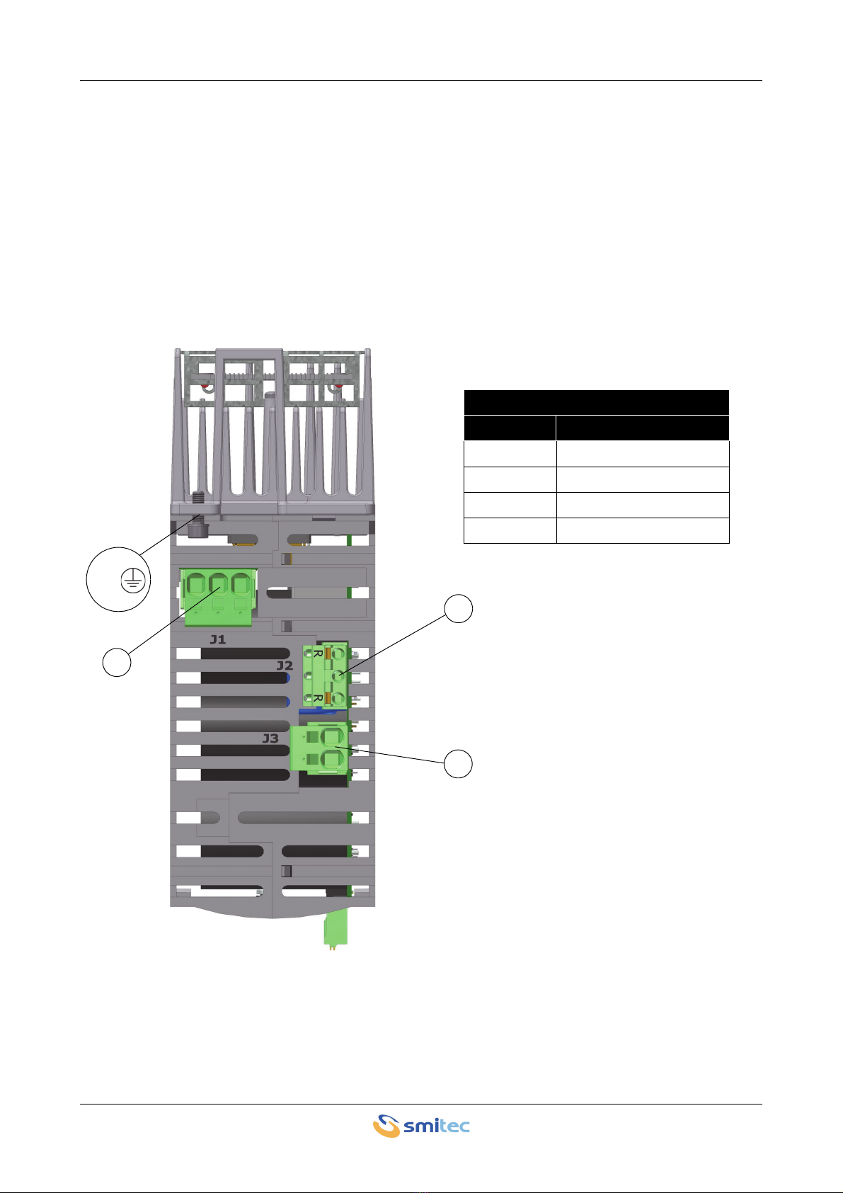
5.4.1 Upper view
The following picture shows the connections available on the upper face of the device:
Connections
Marking Description
J1 Main supply
J2 Braking/discharge resistor
J3 DC BUS output
PE Protective Earth/Ground
J2
J3
J1
PE/
Power supply ICOS-PS 3160 series Installation, use and maintenance manual - EN
Ver. 1.05 19
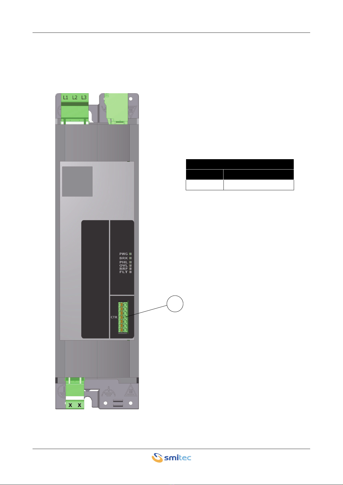
5.4.2 Front view
The following picture shows the connections available on the front face of the device:
Connections
Marker Description
CTR Auxiliary power and I/Os
CTR

Power supply ICOS-PS 3160 series Installation, use and maintenance manual - EN
Ver. 1.05 20
5.4.3 Bottom view
The following picture shows the connections available on the bottom face of the device:
J4
Connections
Marker Description
J4 Reactor (if not used, connect a
jumper using 6 mm2/ 8 AWG wire.)
This manual suits for next models
2
Table of contents
Popular Power Supply manuals by other brands


Meanwell
Meanwell HEP-1000 installation manual

MICRO-POWER
MICRO-POWER PAP3200 manual

TYCON Solar
TYCON Solar RemotePro RPSTL 12 quick start guide

Alarm SAF
Alarm SAF RMMV Series Operating and installation instructions

DekoLight
DekoLight BASIC CC50018 Product notes

B+K precision
B+K precision MR Series user manual