Micropower Oy, Joensuunkatu 7 D, FI-24100, Finland
www.micropower.fi
Installation
The location must be dry, dust-free and indoors. Equipment must be connected to an earthed input socket outlet. For
unplugging the unit, make sure the wall socket is near and in an easy access area. The acceptable full power temperature
range is 0°C…+40°C. The thermal protection will cause the unit to power down at too high an operating temperature. The
power supply is not waterproof. Keep it dry and away from areas with high humidity to avoid the risk of electrical shock and
damage to the charger.
Wall mounting
The power supply can be mounted to the wall with the two mounting holes on
both ends of the power supply unit as shown in the figure.
It is recommended that the power supply is mounted vertically on to the wall.
It is suitable for mounting on a concrete or other non-combustible surface
only.
Leave at least 10 cm free space at the cooling fan end and at both sides of the
power supply to ensure sufficient ventilation.
When used as a charger, the charging process generates explosive hydrogen
gas. Install the power supply as far away from the battery as possible to
prevent hydrogen gases from entering the charger. Keep the area well
ventilated. Never use an open flame or equipment that produces sparks close to the power supply and battery.
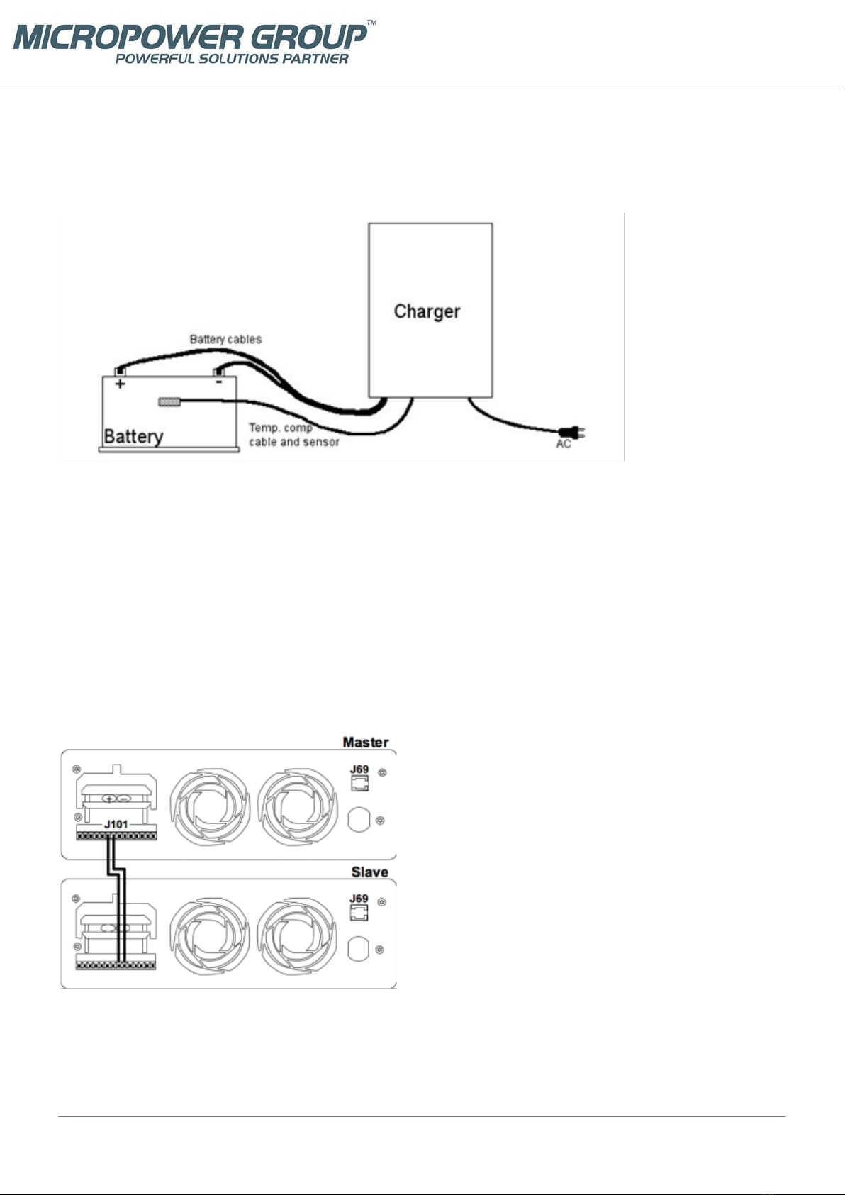
Charging operation
1. Ensure that the power supply is switched off and that the environment meets the conditions as described in the
previous section.
2. Connect the output cables to the load / battery terminals: + cable to the + terminal and –cable to the –terminal
3. Turn the power on by turning the switch to position 1.
4. During normal power supply operation / charging process, the STATUS LED is continuously orange.
5. To avoid sparking, turn off the power supply before disconnecting the cables.
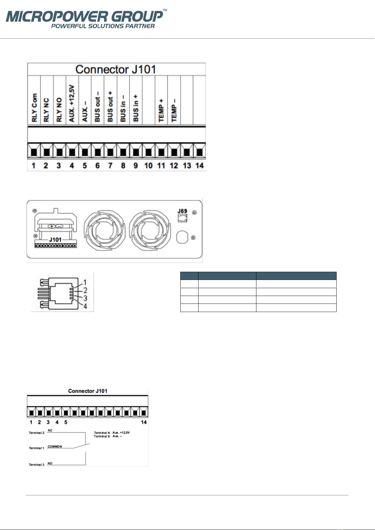
DC Input connection
The power supply input cable is connected as follows:
L negative or positive DC supply input
N positive or negative DC supply input
PE protective earth
Output voltage and current limit adjustment
Trimmer or analog control adjustable modules, type example PAP3200/24 or PAP3200/24AI:
The output voltage and output current limit of the power supply can be adjusted as follows:
•Trimmer adjustable models: with the multi-turn potentiometers accessible from the top cover.
•Analog controllable models by an external 0-5 VDC voltage. See detailed description.
Both voltage and current can be adjusted from zero to the maximum value. Maximum 3200 W / 3000 W output power is
available within the adjustment range.
Temperature compensated models, type example PAP3200/24T:
The power supply includes 16 pre-programmed output voltages that are set by the code switch. See the setting table for
this unit. Any of these 16 different voltage settings can be taken in use and additionally be adjusted within ±5% using the
trimmer on the top cover. See the instructions for choosing the programmed voltage and the fine-tune adjustment.
LED
STATUS LED indicates different phases during the charging process. In normal power supply operation,an orange led
indicates a healthy output voltage.
Stand-by LED is ON when input network (AC) is connected, but the power supply’s output is switched OFF by the switch on
top cover. Stand-by LED goes OFF when the power supply’s output is switched ON.