Section 2
Applicable Standards / Documents
NFPA Standards
NFPA 72 National Fire Alarm Code
NFPA 70 National Electrical Code
US Standards
UL 294 Access Control System Units
UL 1076 Proprietary Burglar Alarm Units and Systems
UL 1481 Power Supplies for Fire Protective Signaling System
UL 2044 Commercal Closed-Circuit Television Equipment
Canadian Standards
ULC S318 Standard for Power Supplies for Burglar Alarm Systems
ULC S527 Standard for Control Units for Fire Alarm Systems
CAN/CSA-C22.2 No. 107.1-01 General Use Power Supplies
CAN/CSA C22.2 No. 1-98 Audio, Video, and Similar Equipment
Other
MEA Listed
California State Fire Marshal (CSFM) Listed
Applicable Local and State Building Codes
Requirements of the Local Authority Having Jurisdiction (LAHJ)
Note - Although the AC and DC sections of this product comply with the above certifications
separately, this preliminary unit as a whole has not yet been listed as a separate product with the
listing agencies.
FCC Compliance
This equipment has been tested and found to comply with the limits for Class A digital device pursuant to Part
15 of FCC rules. These limits are designed to provide reasonable protection against harmful interference
when this equipment is operated in a commercial environment. This equipment generates, uses, and can
radiate radio frequency energy and, if not installed and used in accordance with the instruction manual, may
cause harmful interference to radio communications. Operation of this equipment in a residential area is likely
to cause harmful interference, in which case, the user is required to correct the interference at his/her own
expense.
Listing Compliance Note
This product carries an ETL Listing from Intertek for one or more of the standards listed above. Intertek is
recognized by the Occupational Safety and Health Administration (OSHA) as a Nationally Recognized Testing
Laboratory (NRTL) and accredited by the Standards Council of Canada as a Testing Organization and Certifying
Body. The ETL Listed Mark is recognized by local inspectors and Authorities Having Jurisdiction (AHJs)
throughout North America. As Intertek is an NRTL recognized by OSHA, the ETL Listed Mark is an accepted
alternative to UL and, as such, inspectors and AHJs recognize, acknowledge, and accept the mark as proof of
product compliance. For more information about the NRTL program, we encourage you to visit the OSHA
Web site at www.osha.gov.
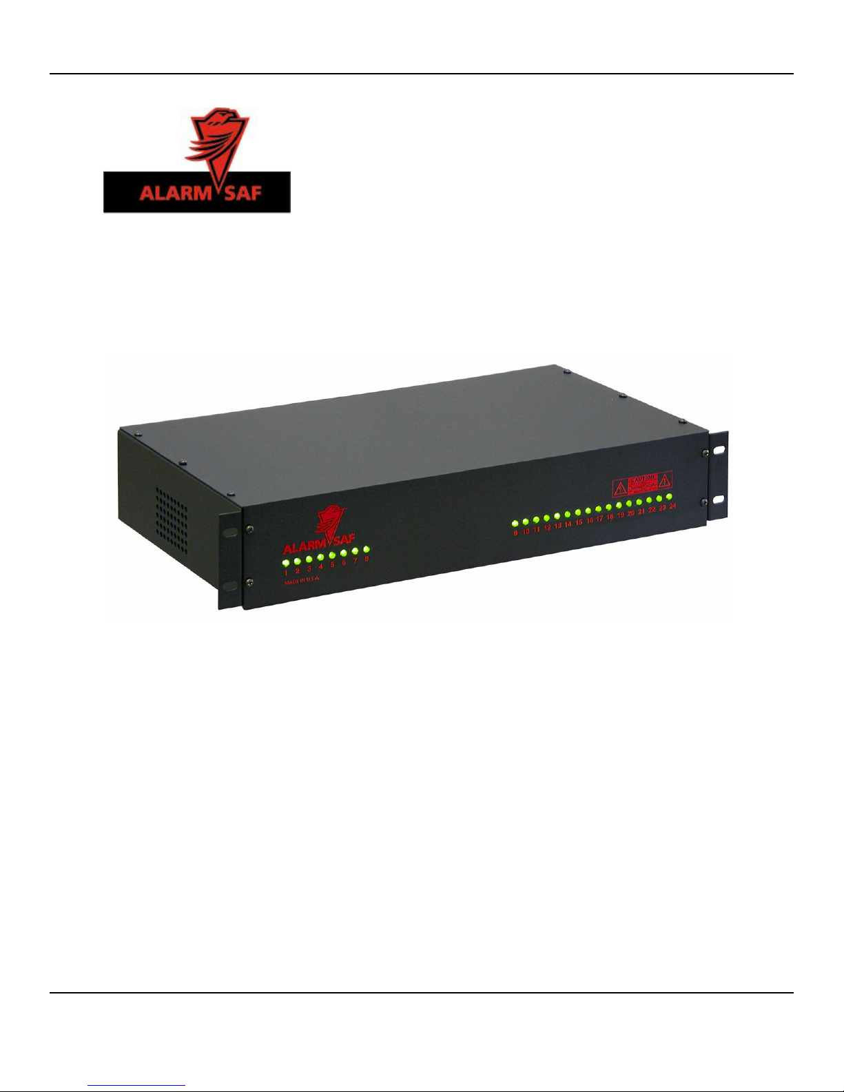
RMMV Series Installation Instructions
7/13/2009, 10:26:56 AM
52-391 Rev A.02
Page 5 of 20
AlarmSaf 65A Industrial Way, Wilmington, MA 01887 978 658 6717 www.alarmsaf.com