Smithco 72-000-A User manual

OPERATOR’S
MANUAL
BIG VAC
Models 72-000-A
Starting Serial # 72001 May, 2001
SMITHCO PRODUCT SUPPORT
1-800-891-9435
Hwy SS and Poplar Avenue, Cameron WI 54822
E-mail: [email protected]

Introduction Service Diagrams Parts Accessories Reference
CONTENTS
Introduction .........................................1-10
Introduction ............................................................................1-8
Introduction.............................................................................. 1
Symbols ................................................................................2-3
Safe Practices ......................................................................... 4
PTO Safety Warnings .............................................................. 5
Specifications........................................................................... 6
OPtional Equipment................................................................. 6
Setup ....................................................................................... 7
Overloading Debris Hopper and Vacuum Housing Wear ........ 7
Controls & Instruments ............................................................ 8
Service ....................................................................................... 9
Operation................................................................................. 9
Diagrams............................................................................. 10-11
Hydraulic Drawing............................................................. 10-11
Other......................................................................................... 12
Declaration of Conformity-English.......................................... 12
Warranty........................................................Inside Back Cover

1
Introduction
Informationneededwhenorderingreplacementparts:
1. ModelNumber ofmachine
2. SerialNumber ofmachine
3. Nameand Part Numberofpart
4. Quantityof parts
INTRODUCTION
Thankyou for purchasing a product.
Read this manual and all other manuals pertaining to the Big Vac carefully as they contain safety, operating,
assembly and maintenance instructions. Failure to do so could result in personal injury or equipment damage.
Keepmanuals in a safe place afteroperatorand maintenance personnel have read them. Rightandleft sides are
fromthe operator’s seat,facing forward.
All machineshave a Serial Numberand Model Number.Bothnumbers are needed whenordering
parts.The serial number plate on the Big Vac is located on the front cross member of the frame.
For easy access record your Serial and Model numbers here.

2
Introduction
SYMBOLS
ParkBrake Park Brake
Release HydraulicOil
Level
Choke- OpenChoke- ClosedHandThrottle
HourMeter HourMeter Fuse
GlowPlugGlowPlug - OffGlow Plug - On
RPM Gasoline Diesel
Water
Temperature
Temperature
Light
EngineOil
Engine - Stop Engine - Start Engine -Run
No Electrical
Power
ElectricalPower
ReadOperator’s
Manual
Off / Stop On / Start

3
Introduction
SYMBOLS
NoSmoking Moving Parts Manual
Operation
Pinch Point Step HotSurface
HydraulicFluid
Penetration LiftArm Tractor
Engage Disengage PTO
GroundSpeed Fast Slow
HHigh LLow FForward
RReverse NNeutral Warning
Danger
Caution
Up/RaiseDown/LowerUp/DownArrow

4
Introduction
SAFEPRACTICES
1. It is your responsibility to read this manual and all publications associated with this machine (engine, accesso-
ries and attachments).
2. Never allow anyone to operate or service the machine or its attachments without proper training and instructions.
Never allow minors to operate any equipment.
3. Learn the proper use of the machine, the location and purpose of all the controls and gauges before you operate
the equipment. Working with unfamiliar equipment can lead to accidents.
4. Wear all the necessary Personal Protective Equipment (PPE) on your head, eyes, ears, hands and feet. Ear and
eye protection are required. Operate the machine only in daylight or in good artificial light.
5. Inspect the area where the equipment will be used. Beware of overhead obstructions and underground ob-
stacles. Stay alert for hidden hazards.
6. Never operate equipment that is not in perfect working order or without decals, guards, shields, or other protec-
tive devices in place.
7. Never disconnect or bypass any switch.
8. Carbon monoxide in the exhaust fumes can be fatal when inhaled, never operate a machine without proper
ventilation.
9. Never use your hands to search for oil leaks. Hydraulic fluid under pressure can penetrate the skin and cause
serious injury.
10. This machine demands your attention. To prevent loss of control or tipping of the vehicle:
A. Use extra caution in backing up the vehicle. Ensure area is clear.
B. Do not stop or start suddenly on any slope.
C. Reduce speed on slopes and in sharp turns. Use caution when changing directions on slopes.
D. Stay alert for holes in the terrain and other hidden hazards.
E. Operate equipment up and down slopes, never across the face.
11. Before leaving operator’s position for any reason:
A Disengage all drives.
B. Lower all attachments to the ground.
C. Shut engine off and remove the ignition key.
12. Keep hands, feet and clothing away from moving parts. Wait for all movement to stop before you clean, adjust or
service the machine.
13. The rubber fingers, sweeper and vacuum pick up and propel debris and small objects in the machines path
during operation. Keep the area of operation clear of all bystanders.
14. Never carry passengers.
15. Use parts and materials supplied by SMITHCO only. Do not modify any function or part.
16. Avoid sharp turns. Watch the tires of the tractor while turning to make sure they do not contact the tongue of the
BigVac.
17. Shut down power source before attempting to unclog any part of the machine.
18. If reel deck and/or blower began to vibrate abnormally, immediately shut off power and determine the cause.
These machines are intended for professional maintenance on golf courses, sports turf, and any other
area maintained turf and related trails, paths and lots. No guaranty as to the suitability for any task is
expressed or implied.

5
Introduction
PTOSAFETYWARNINGS
1. Alwaysdisengage the PTO, shut off engine and removethekeys before leaving the tractor seat.
2. Keep the tractor's master shield in place at all times.
3. Missing or damaged shieldingis the main reasonfor driveline entanglement. Keep All Guards onandin
goodcondition. Check guardsfrequently.
4. Never stepacross a rotatingpowershaft.Alwayswalk around the revolving shafteven if guards arein
place.
5. Dress for safety. Do not wear loose fitting clothes or jewelry and keep long hair covered or pulled back.
6. Thetractor drawbar should be adjusted to thelengthspecified in the driven machine's manual. This will
helpprevent driveline stressandseparation on uneventerrainand in tight turns.
7. APTO shaft may break or separate during operation if improperlyinstalledoradjusted. Be sure PTO shaft
is installed properly.
8. Neverperform maintenance oradjustments until boththe driveline andthemachinery have stopped
moving.
9. Warnanyone who might come nearan operating PTO about the entanglementhazard.
10. Regularly test driveline guards by spinning or rotating them to ensure the have not become stuck to the
shaft.
11. Always usethe driveline recommendedfor your machine.Neverswitch drivelinesamongdifferent ma-
chines.
12. Reduce PTOshaftabuse by observingthe following:
a. Avoid tight turns that pinch rotating shafts between the tractor and machine.
b. Keep excessive telescoping to a minimum.
c. Engage power totheshaft gradually.
d. Avoidover tightening of slipclutches on PTO drivenmachines.

6
Introduction
SPECIFICATIONS
FORBIGVAC
WEIGHTSANDDIMENSIONS
Length 180"(458 cm)
Width 84"(214 cm)
Height 87"(221 cm)
Weight 3500lb (1588 kg)
SOUNDLEVEL
AtEar Level 92 dB(Useear protection while operating)
PTOSHAFT
MaximumRPM 540
TIRES&WHEELS Two 26.5 - 1400 x 12(18psi(1.3 bar)) FairwayTypeTurfTires
Castor: 6 x 12 (20 psi (1.4 bar))
FLUIDCAPACITY
HydraulicFluid 10 gallon (37.85liters)
Grade of HydraulicFluid SAE 10W-40API Service SJ or higher Motor Oil
OPTIONALEQUIPMENT
72-001 CombinationVerticut andSweeper Head
72-002 RubberFingerSweeperHead
72-245 25/16 Ball Hitch

7
Introduction
SETUP
The Big Vac arrives from with some setup required.
1. The PTO shaft and the rubber boot that goes around the blower and the reel need to be installed.
2. You will need a 40 HP (minimum) tow vehicle to remove the Big Vac from the trailer.
a. Clevis Hitch - You will need a 3/4diameter by 4" pin with some type of lock.
b. Ball Hitch (optional) - You will need a 25/16" ball and a locking pin for the coupler.
3. Crank the jack on the Big Vac up so you can hook to tow vehicle.
4. Check the tire pressure. Big Vac: 18 psi (1.3 bar) Castor Wheels: 20 psi (1.4 bar).
5. Check hydraulic fluid level in tank. Look at the sight gauge on the front left side of the tank.
The oil level should be at 90°C (194°F). If level is low, add SAE 10W-40API Service SJ or
higher motor oil.
6. Machine should be greased before starting. See Maintenance part of manual.
7. Lower reel all the way down. Place rubber boot onto the bottom of the blower housing.
Raise the reel up 3/4 of the way. Stretch rubber boot around lip on reel. Lift and lower
several times to ensure boot is on properly.
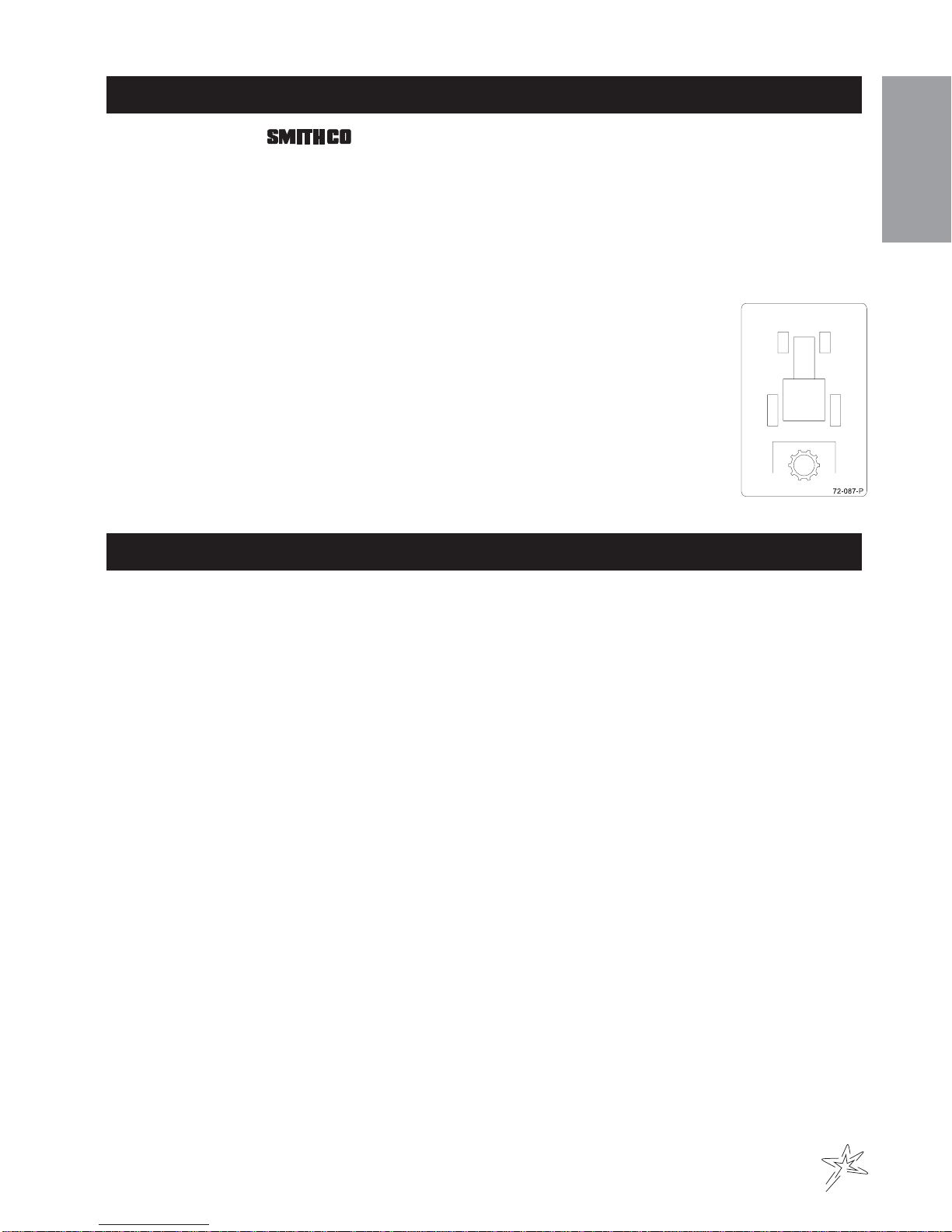
8. When installing PTO shaft be sure the end with the tractor decal (72-087) goes to the tow
vehicle. If PTO Shaft is put on wrong it will bust when engaged.
9. Read operating instructions before starting.
OVERLOADINGDEBRISHOPPERANDWEARONVACUUMHOUSING
OVERLOAINGDEBRIS HOPPER
Smithco Sweeper-Vacs are designed to carry the following maximum loads:
Model 72-000 Big Vac 1500 lbs. (608 kg)
PLEASENOTETHEFOLLOWING:
1. Loads heavier than that will damage the unit.
2. Such damage is not covered by warranty.
3. Overloading is particularly easy when collecting aerifier cores.
4. The hoppers on the Big Vac and V62 are large in order to hold 7 and 4 cubic yards respectively, of thatch, grass
clippings, leaves and trash.
5. They will not hold 7 or 4 cubic yards of aerifier cores.
6. The maximum depth (in the debris hopper) of aerifier cores is:
Model 72-000 Big Vac 12 in. (30 cm)
VACUUM HOUSING WEAR
The Big Vac & V62 are fitted with a wear resistant liner in the vacuum housing. This will provide additional husing life.
Be sure the following points are explained to the user:
1. The vacuum housing and impeller must be cleaned each time the unit is used so the housing liner is inspected
daily. Only Smithco Sweeper-Vacs provide a clean out/inspection port for easy inspection and cleaning.
2. When bare steel is visible at any point in the housing lining, the lining must be replaced. It is expected the liner
will wear and be replaced. It is a vast improvement over competitive units with no liners.
3. Replacement of the liner or the vacuum housing due ti wear is normal and is not covered by warranty.
4. Collection of aerifier cores causes extreme wear on the liner (and if unchecked, on the housing).
5. Caution users that, while Smithco Sweeper-Vacs do an excellent job collecting cores, the lining (and the
housing) will wear quickly in such use.
RUBBERIZED BOOT
The rubberized boot between main unit and sweeper head is subject to wear and damage from debris. Unless
defecetive, replacement of this boot is not covered by warranty.

8
Introduction
CONTROLS&INSTRUMENTS
A. Hopper Lever - The hopper
lever is used to lift and lower
thehopper which also opens
andclosesthetailgate. Refer
todecal for direction.
B. Finger Reel Off-On Valve -
Turnsthe reel onor off. Refer
todecal for direction.
C. Deck Lift Lever - The deck
lift lever is used to raise and
lowerthe reel. Refer to decal
fordirection.
D. Thatch Reel Off-On Valve -
Turnsthe reel onor off. Refer
todecal for direction.
HOPPERLIFTSAFETY
TheHopperLiftSafetyisusedtosupport
the ram on the hopper bottom in the extended position so you may service or repair the machine under the hop-
per. When not in use the Hopper Lift Safety can be stored on the hopper bed frame.

9
Service
OPERATION
Before operating this machine, become familiar with all controls and functions of this unit and the tow vehicle.
Alsocomplete all maintenance requirements and read all safety warnings. By knowing both machines thor-
oughly,how it operates and by doing the prescribedmaintenancesteps,you can expect relatively trouble-free
operationfor years to come.
TOWVEHICLE
You will need a 40 HPminimum tow vehicle.
1. Clevis Hitch - You will need a 3/4diameter by 4" pin with some type of lock.
2. Ball Hitch - You will need a 25/16" ball and a locking pin for the coupler.
DAILYCHECKLIST
1. Check engineoillevelin tow vehicle. Add as needed. DO NOTOVERFILL.
2. Tire pressure should be 18 psi (1.3 bar) on Big Vac tires and 20 psi (1.4 bar) on castor wheels.
3. Check hardware for loose or missing nuts, bolts, screws, etc., and tighten or replace as needed.
4. Inspect hydraulic lines for damage or leaks. Never use hands to inspect leaks.
5. Check hydraulic fluid level in tank. Look at the sight gauge on the front left side of the tank. The oil level
should be at 90°C (194°F). If level is low, add SAE 10W-40API Service SJ or higher motor oil.
6. Checkcontrols for smooth, properworkingoperation. Lubricate as needed.
7. Checkand clean all debris from blowerhousing.
ADJUSTMENTOFBELTTENSIONER
There are four maximum belt tensioners on the Big Vac. Two control the tension
on the belts on the blower housing, one each on the finger reel and the thatcher
reel. The proper tension of the idler should be 12 to 15 as per the gauge (A) on
the side of the tightener. Over tightening the belt will shorten the life of the belt
and the machine may not perform to the best of its ability. To adjust belt
tensioner, loosen bolt holding tensioner. Bring idler pulley tight to belts and turn
tensioner into belts to 15°. Tighten holder bolt.
CONTROLPANELADJUSTMENTARM
On the right hand side of machine is the
adjustment lock arm, by lifting up you can
adjustthe control panel by moving itforward
or rearward. Make certain that the lock arm
is locked back in place after adjustment.
Forup and down adjustment loosenthefour
adjustment bolts place the control panel to
where you want it and tighten the four bolts.
HITCHOPTIONS
You may use the clevis hitch that is shipped
with your machine or a 25/16 ball hitch that is
an optional accessory. Both mount in the
samelocation with three different bolt hole
options.

10
Diagrams
HYDRAULICDRAWING

11
Diagrams
HYDRAULICPARTSLIST
REF# PART# DESCRIPTION QUANTITY
1 72-079 SuctionHose 2
2 18-276 Tee Fitting 11/41
3 60-215 Filter 1
60-334 Filter Element (replacement only) 1
4 72-096 HydraulicTank 1
5 34-058 SwivelTee 1
6 72-065 HydraulicHose 1
7 72-040 Cylinder 1
72-040-01 Seal Kit 1
72-040-02 Pin with Clips (part of 72-040) 2
8 72-064 HydraulicHose 1
9 72-070 HydraulicHose 1
10 72-071 Hydraulic Hose 2
11 10-187 Hydraulic Cylinder 1
14-273 Seal Kit 1
12* 72-022 Hydraulic Motor (Thatch Reel) 1
78-219-01 Seal Kit 1
78-219-02 DriveCoupler 1
13 72-073 Hydraulic Hose 2
14 72-044 Quick Coupler 3/8Male End 1
15 72-045 Quick Coupler 3/8Female End 1
16 72-072 Hydraulic Hose 1
17 18-170 Tee Fitting 1
18* 78-219 HydraulicMotor (Reel) 1
78-219-01 Seal Kit 1
78-219-02 DriveCoupler 1
19 72-075 Hydraulic Hose 1
20 72-074 Hydraulic Hose 1
21 72-043 Quick Coupler ½ Male End 4
22 72-046 Quick Coupler ½ Female End 4
HRR-150 RetainingRing 1½" External 8
23 72-068 Hydraulic Hose 2
24 72-074 Hydraulic Hose 2
25 72-067 Hydraulic Hose 2
26 72-063 Hydraulic Hose 1
27 33-066 Hydraulic Valve 1
28 72-069 Hydraulic Hose 1
29 78-416 Hydraulic 3 Bank Valve 1
30 72-062 Hydraulic Hose 1
31* 72-021 HydraulicPump (Double Pump) 1
72-021-01 Seal Kit 1
32 72-066 Hydraulic Hose 1
* No other parts are replaceable for hydraulic motor or pump.
HYDRAULICPRESSURES FRONT REAR
PumpDisplacement .90in3/rev .40in3/rev
PumpInput Speed (up to) 4000rpm 4000rpm
Max.Operating Pressure 3600 psi 3600psi
Max. Inlet Vacuum 10 in. Hg 10 in. Hg
Max. Case Pressure 80 psi 80 psi

12
ECDECLARATIONOFCONFORMITY
according to Directive 89/392/EEC
We SMITHCO INC.
(Name of supplier)
34 West Ave. Wayne, PA 19087 USA
(Full address of the manufacture - authorized representative established in the Community must also give the business name and
address of the manufacture)
declareunder our sole responsibility,thattheproduct
Big Vac / 72-000-A
(Make,Model)
towhich this declaration relates corresponds to the relevant basic safety and health requirements of theDirec-
tive89/392/EEC,
(ifapplicable)
andto the requirements of the otherDirectives:
EN292-1
EN292-2
EN294
EN349
92/59
89/392
(Title and/or number and date of issue of the other Directives)
(ifapplicable)
Forthe relevant implementation ofthesafety and health requirementsmentionedin the Directives, the following
standard(s)and/or technical specification(s)has (have) beenrespected:
ISO 37-1983
PREN 836
ISO 1219-1976
SAE HS-2800
SAE J1362
(Title and/or number and date of issue of standard(s) and/or technical specification(s))
Cameron, Wisconsin USA
March 19, 1995
(Place and date of issue) (Name, functionandsignature of theauthorized person)

LIMITED WARRANTY
SMITHCO warrants this product to be free from defects in material and workmanship under normal
use for one year from the date of purchase by the original user. (60 days if product is used for rental
purposes.) All warranty claims must be handled through a SMITHCO authorized dealer or by
SMITHCO, INC. All transportation charges must be paid by the purchaser.
There is no further express warranty. All implied warranties, including those of merchantability and
fitness for a particular purpose, are limited to one year, (60 days if product is used for rental pur-
poses) from the date of purchase by the original user, and to the extent permitted by law any and all
implied warranties are excluded and disclaimed after the expiration of such period.
All incidental and consequential damages, including pickup and delivery of the unit, communica-
tion, mileage charges and/or rental of a replacement unit during repair, are not covered under this
warranty, nor is any loss of income and/or other loss resulting from the failure of the product to
function due to a warranty defect.
The following items are not covered under the SMITHCO warranty, and are warranted by their
respective manufacturer.
(a) Engine and engine parts, including starters, generators, alternators and filters.
(b) Transaxle, differentials, gear boxes and mechanical pumps.
(c) Hydrostatic transmissions, hydraulic pumps and motors.
(d) Batteries.
(e) Wheels and tires.
A copy of the warranty for the above items is furnished if necessary with each SMITHCO product.
Some states do not allow limitations on how long an implied warranty lasts, or the exclusion or
limitations of incidental or consequential damages, so the above limitations or exclusions may not
apply to you. This warranty gives you specific legal rights and you may also have other rights, which
may vary from state to state.
Federal law now requires disclosure of the warranty which applies to this product prior to the sale to
a customer. Please leave this statement attached to the product and allow the buyer to remove it
after purchase.

This manual suits for next models
1
Table of contents
Other Smithco Lawn Sweeper manuals
Popular Lawn Sweeper manuals by other brands

Brinly-Hardy
Brinly-Hardy STH-420BH owner's manual

Agri-Fab
Agri-Fab 26" Leaf/Lawnsweeper 45-02181 owner's manual

MasterCraft
MasterCraft HS 700 S operating instructions

Lawn Tender
Lawn Tender SW380LT owner's manual

Kärcher
Kärcher KMR 1250 B User instructions

Parker
Parker Thatch-o-matic PR-7819-T instructions