Smithco 1803 Quick start guide

Product Support: Hwy SS & Poplar Ave; Cameron WI 54822
1-800-891-9435 productsupport@smithco.com
Parts & Service
April 2005
Revised June 2006
SweepStar 60
Gas and Diesel
76-000-C and 77-100-C
SN: 1803

Introduction Service Diagrams Parts Accessories Reference
CONTENTS
Introduction .........................................1-10
Introduction...................................................................................1-3
SafePractices.............................................................................2
Specifications ..............................................................................3
OptionalEquipment .....................................................................3
Service ........................................................................................ 4-11
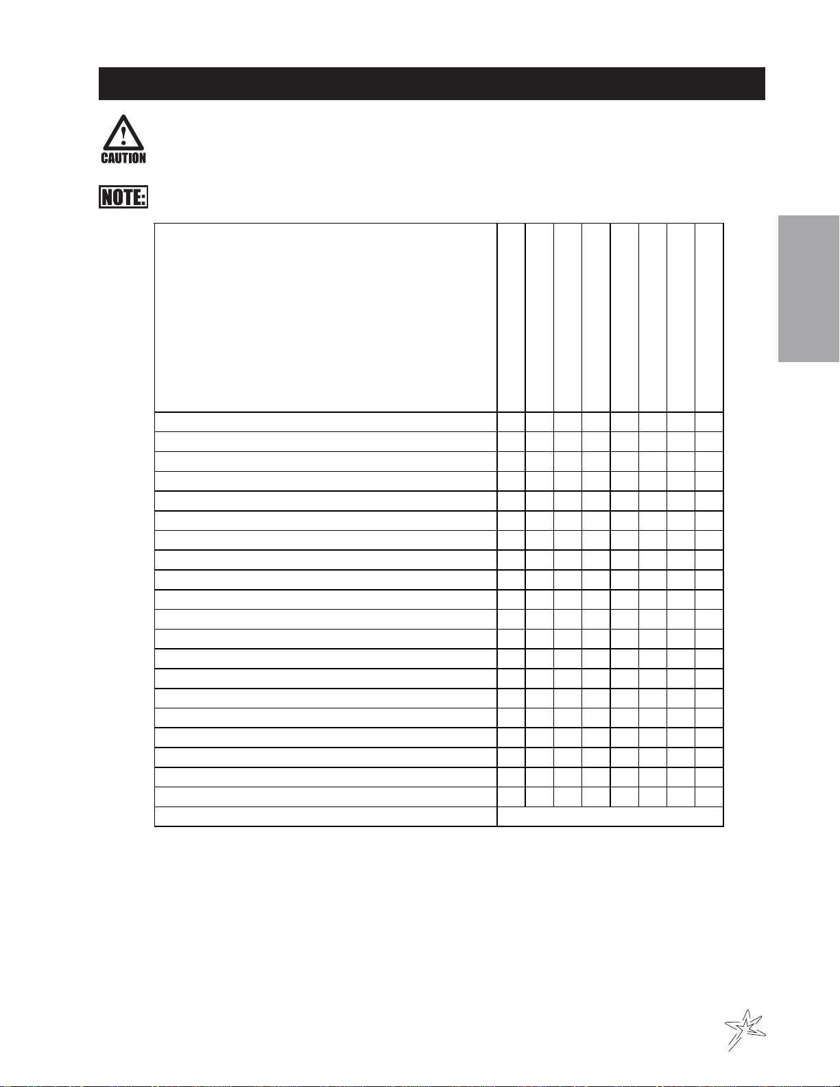
Maintenance.............................................................................4-6
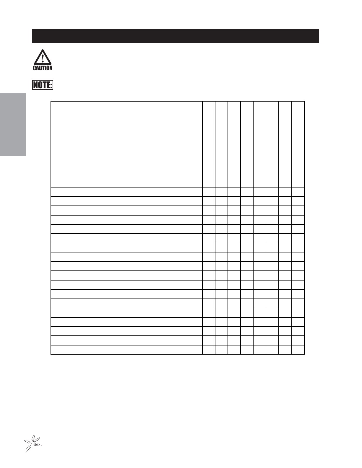
ServiceChartKohlerCommand 25 hp .........................................7
ServiceChartKubotaDiesel18.8hp............................................8
EndUser’s Service Chart.............................................................9
Adjustments ..............................................................................10
Storage ......................................................................................10
Notes ........................................................................................ 11
Diagrams ................................................................................... 12-17
DieselWiringDiagram .......................................................... 12-13
GasWiring Diagram ............................................................. 14-15
HydraulicDiagram ................................................................ 16-17
Parts .......................................................................................... 18-65
Bodyand Frame ................................................................... 18-19
RollOver Protection(ROPS)................................................. 20-21
Steering ................................................................................ 22-23
FrontFork ............................................................................ 24-25
GasolineLinkage.................................................................. 26-27
DieselLinkage ...................................................................... 28-29
GasConsole ........................................................................ 30-31
DieselConsole ..................................................................... 32-33
Fuel Tank and Oil Tank ......................................................... 34-35
Oil Filter ............................................................................... 36-37
HydraulicLift Cylinder........................................................... 36-37
ReelLift Cylinder .................................................................. 38-39
TailgateCylinder ................................................................... 38-39
KohlerGas Engine and Exhaust........................................... 40-41
KubotaDieselEngine and Exhaust ...................................... 42-45
ElectricClutch Driven BeltDrive............................................ 46-47
FingerReel ........................................................................... 48-49
RearAxle.............................................................................. 50-53
Hopper.................................................................................. 54-55
Tailgate................................................................................. 56-57
77-239Eaton Hydrostatic Pump ........................................... 58-59
76-197Eaton GearPump ..................................................... 60-61
76-238Rear WheelMotor ..................................................... 62-63
76-0233-Bank HydraulicValve ............................................. 64-65
Accessories ............................................................................... 66-67
76-271 Dust/Dirt Filtration Pack........................................... 66-67
Reference.................................................................................. 69-70
Decal List .................................................................................. 69
QuickReference Replacement Parts .........................................70

1
Introduction
Informationneededwhenordering replacementparts:
1. ModelNumber ofmachine.
2. SerialNumber of machine.
3. Nameand Part Number of part.
4. Quantity of parts.
INTRODUCTION
Thankyou for purchasing a product.
Readthis manual and all other manuals pertaining to the Sweep Star 60 carefully as they have safety, operating,
assembly and maintenance instructions. Failure to do so could result in personal injury or equipment damage.
Keepmanuals in a safe place after operatorandmaintenance personnel have read them. Right andleftsidesare
fromthe operator’s seat,facingforward.
All machineshave a Serial NumberandModel Number. Both numbers are neededwhenordering
parts. The serial number plate on the Sweep Star 60 is located on the left front main frame, in front of the engine.
Referto engine manualforplacement of engineserialnumber.
For easy access record your Serial and Model numbers here.

2
Introduction
SAFEPRACTICES
.It is your responsibility to read this manual and all publications associated with this machine (engine, accessories
and attachments).
2. Never allow anyone to operate or service the machine or its attachments without proper training and instructions.
Never allow minors to operate any equipment.
3. Learn the proper use of the machine, the location and purpose of all the controls and gauges before you operate
the equipment. Working with unfamiliar equipment can lead to accidents.
4. Wear all the necessary protective clothing and personal safety devises to protect your head, eyes, ears, hands
and feet. Operate the machine only in daylight or in good artificial light.
5. Inspect the area where the equipment will be used. Beware of overhead obstructions and underground ob-
stacles. Stay alert for hidden hazards.
6. Never operate equipment that is not in perfect working order or without decals, guards, shields, or other protec-
tive devices in place.
7. Never disconnect or bypass any switch.
8. Carbon monoxide in the exhaust fumes can be fatal when inhaled, never operate a machine without proper
ventilation.
9. Fuel is highly flammable, handle with care.
10. Keep engine clean. Allow the engine to cool before storing and always remove the ignition key.
11. After engine has started, machine must not move. If movement is evident, the neutral mechanism is not ad-
justed correctly. Shut engine off and readjust so the machine does not move when in neutral position.
13. Never use your hands to search for oil leaks. Hydraulic fluid under pressure can penetrate the skin and cause
serious injury.
14. This machine demands your attention. To prevent loss of control or tipping of the vehicle:
A. Use extra caution in backing up the vehicle. Ensure area is clear.
B. Do not operate on a slope greater than 10°. Pay carefuk attention to the inclinometer on you machine.
C. Do not stop or start suddenly on sloped surfaces.
D. Reduce speed on slopes and in all turns. Use caution when changing directions on all surfaces.
E. Do not change directions of travel on any slope.
F. Do not operate debris hopper lift or tailgate while on slopes.
G. Stay alert for holes in the terrain and other hidden hazards.
15. Before leaving operator’s position for any reason:
A. Disengage all drives.
B. Lower all attachments to the ground.
C. Set park brake.
D. Shut engine off and remove the ignition key.
16. Keep hands, feet and clothing away from moving parts. Wait for all movement to stop before you clean, adjust or
service the machine.
17. Keep the area of operation clear of all bystanders.
18. Never carry passengers.
19. Stop engine before making repairs/adjustments or checking/adding oil to the crankcase.
20. Use parts and materials supplied by SMITHCO only. Do not modify any function or part.
21. Do not remove the radiator cap when the engine is hot. When cooled, loosen cap slightly to the stop to relieve
any pressure before removing the cap completely.
These machines are intended for operation by well trained persons performing professional maintenance on golf
courses, sports turf, and any other area maintained turf and related trails, paths and lots. No guaranty as to the
suitability for any task is expressed or implied.

3
Introduction
SPECIFICATIONS
FORSWEEPSTAR60GAS&DIESEL
WEIGHTSANDDIMENSIONS
Length 129"(328 cm)
Width 74.5"(179cm)
HeightwithHopperDown 82" (208 cm)
Heightwith HopperUp 127" (323 cm)
Wheel Base 68.5" (174 cm)
Weight 2200 lbs (998 kg)
ROLLOVERPROTECTIONBAR
Standardon all Machines
SOUNDLEVEL GASENGINE DIESEL ENGINE
At earlevel 92 dB 98 dB
At 3 ft (0.914 m) 86 dB 96 dB
At 30 ft (9.14 m) 64 dB 74 dB
ENGINE GAS DIESEL
Make Kohler Kubota
Model# CommandCH25S D722B-1
Type /Spec# PA-68525
Horsepower 25 Hp (18 kw) 18.8 Hp (14 kw)
Fuel Unleaded87 Octane No. 2 Diesel
GasolineMinimum
CoolingSystem Air Cooled LiquidCooled
LubricationSystem Full Pressure FullPressure
Alternator 15Amp 40Amp
Tire&Wheels Front: One 18 x 9.50 x 8 Multi-rib (20 psi; 1.4 bar)
Front tire and wheel fluid filled to 50 lbs. total. 28 pints of windshield washer
fluidorequivalent.
Rear: Two 24 x 13.00 x 12 Super Soft (18 psi; 1.3 bar)
Castor: 9 x 3.5 - 4 (20 psi; 1.4 bar)
SPEED
ForwardSpeed 0 to 12 m.p.h. (0-19 kph)
ReverseSpeed 0 to 4 m.p.h. (0-6 kph)
BATTERY Automotivetype 45 -12volt
BCIGroup Size 45
ColdCrankingAmps 480minimum
GroundTerminalPolarity Negative(-)
MaximumLength 9" (23 cm)
Maximum Width 5.38" (14 cm)
MaximumHeight 9" (23 cm)
FLUIDCAPACITY
CrankcaseOil See Engine Manual
Fuel 5 gallon(19liters)
HydraulicFluid 5 gallon (19 liters)
Cooling Kubotaapproximately 1 gallon (3.8 liters)
Grade of Hydraulic Fluid SAE 10W-40API Service SJ or higher Motor Oil
OPTIONALEQUIPMENT
77-328 60" Brush Kit
76-329 60" Finger Reel Kit
76-271 Filtration Pack
77-218 TripleCastor Wheel Kit

4
Service
MAINTENANCE
LUBRICATION
UseNo.2 General Purpose Lithium Base Grease and lubricate every 100 hours.The Sweep Star60 has ten
greasefittings.
One on the outside of each tower.
One on the center of park brake relay on rear axle.
Oneon hydrostatic pedalunderthe floorboard.
Oneonthe pillow block bearing on each end of finger reel.
One on castor wheel mount bracket.
Oneon hydrostaticforwardand reverse relay.
One on reel clutch belt tightener.
One on rod end of the tailgate cylinder.
Every500 hours of operation, separate the hydrostaticpumpfromthe engine. Clean the splined areas and
lightly grease the male portion of the pump spline. Use either Dow Corning®G-N MetalAssembly Paste or
#77Assembly Paste (Kohler # 25 357 12-s).
As you remount the pump to the engine, be certain the mating surface are clean and free of any foreign
material and that the pump is correctly aligned.
HYDRAULICOIL
1. Use SAE 10W-40API Service SJ or higher motor oil.
2. Forproper warranty, change oil every500hours or annually,which ever is first and changethefilterafter
thefirst20 hours, then at 100 hours, then every 250 hours thereafter.
3. The oil level should be 2" to 21/2" from top of the tank when fluid is cold. Do not overfill.
4. After changing oil and/or filter, run the machine for a few minutes. Check oil level and for leaks.
5. Always use caution when filling hydraulic oil tank or checking level to keep system free of contaminants.
Checkandservicemore frequently when operating in extremely cold, hot or dusty conditions.
6. If natural color of fluid is now black or smells burnt, it is possible that an overheating problem exists.
7. If fluid becomes milky, water contamination may be a problem.
8. Ifeither of the above conditions happen, change oil and filter immediatelyafterfluidiscool and find cause.
Take fluid level readings when system is cold.
9. In extreme temperatures you can use straight weight oil. We recommend SAE 30WAPI Service SJ or
higherwhen hot (above90°F(33°C)) and SAE 10WAPIService SJ orhigher when cold (below32°F(0°C))
ambient temperature. Use either motor oil or hydraulic oil, but do not mix.
10. Oil being added to the system must be the same as what is already in the tank. Mark tank fill area as to
which type you put in.

5
Service
MAINTENANCE
(CONTINUED)
TIREPRESSURE
Caution must be used when inflating a low tire to recommended pressure. Over inflating can cause tires to ex-
plode. Front tires and castor wheel should be 20 psi (1.4 bar), rear tires should be 18 psi (1.3 bar) maximum.
Improperinflation will reduce tirelifeconsiderably.
ENGINEOIL FORKOHLER
Changeand add oil according to chartsbelow. Do not overfill. Use a high quality detergent oil. For Kohler engine
use oil classified “For Service SJ or higher” SAE 30 oil. For Kubota Diesel engine use oil classified “For Service
CC, CD or CE”API oil. Use no special additives with recommended oils. Do not mix oil with gasoline.
SAE 30 oil, if used below 40° F (4° C), will result in hard starting and possible engine bore damage due to inad-
equatelubrication. SAEViscosityGrades
Starting Temperature Range Anticipated Before Next Oil Change
TOWING
When it is necessary to move the Sweep Star 60 without engine running, the bypass valve built into hydrostatic
pumpmust be “open” by turning it counterclockwise.The valve is located on bottom leftof pump.An“open”valve
allowsfluid to pass throughthewheelsfreely.Whennormal,driven, operation is desired, valve should beclosed
byturningitclockwise.Failureto“close”the valve with engine running means no power to wheels.
BATTERY
Batteries normally produce explosive gases which can cause personal injury. Do not allow flames, sparks or any
ignited object to come near the battery. When charging or working near battery, always shield your eyes and
alwaysprovideproper ventilation.
Batterycable should be disconnected before using “FastCharge”.
Charge battery at 15 amps for 10 minutes or 7 amps for 30 minutes. Do not exceed the recommended charging
rate.If electrolyte startsboiling over, decrease charging.
Alwaysremovegrounded(-) battery clamp first and replace it last.Avoidhazards by:
1. Fillingbatteries in well-ventilatedareas.
2. Weareye protection andrubbergloves.
3. Avoidbreathing fumes when electrolyteis added.
4. Avoidspilling or dripping electrolyte.
Battery Electrolyte is an acidic solution and should be handled with care. If electrolyte is
splashed on any part of your body, flush all contact areas immediately with liberal amounts
of water. Get medical attention immediately.
FILTERPACK
Filter pack may be cleaned by shaking or spraying off with low pressure water. Filter will disintegrate if high
pressure is used on it.
KohlerGasEngine KubotaDieselEngine

6
Service
MAINTENANCE
(CONTINUED)
WHEELMOUNTINGPROCEDURE
REARWHEELS
1. Setpark brake.Turnmachineoffandremovekey.
2. Block one of the other wheels.
3. Loosennuts slightly on wheel to be removed.
4. Jackup machine being careful not to damage undersideofmachine.
5. Removenuts, removewheel.
5. Place new wheel on hub lining up bolt holes.
6. Torquenuts to64-74ft/lb(87-100Nm)using a cross pattern.Torqueagain afterfirst10 hours and every
200hoursthereafter.
7. Lowermachine to ground and remove blocksandjack.
FRONTWHEEL
1. Setpark brake.Turnmachineoffandremovekey.
2. Block one of the other wheels.
3. Removecotter pins from each end of the axle.
4. Remove axle nuts, machine bushings and axle locks.
5. Jackup front of machine being careful nottodamageunderside of machine.
6. Wheel and axle will come out of slots in the u-bracket, pull wheel forward.
7. Place new wheel on hub lining up bolt holes.
8. Torquenuts to64-74ft/lb(87-100Nm)using a cross pattern.Torqueagain afterfirst10 hours and every
200hoursthereafter.
9. Lowermachine to ground and remove blocksandjack.
JUMPSTARTING
Use of booster battery and jumper cables. Particular care should be used when connecting a
booster battery. Use proper polarity in order to prevent sparks.
Tojumpstart (negativegroundedbattery):
1. Shield eyes.
2. Connectends of one cable to positive (+) termi-
nals of each battery, first (A) then (B).
3. Connectone end of othercableto negative (-)
terminalof "good" battery (C).
4. Connectother end of cable (D) to engine block on
unitbeing started (NOT tonegative(-) terminal of
battery)
To prevent damage to otherelectricalcomponentson
unit being started, make certain that engine is at idle
speedbefore disconnecting jumpercables.
SWEEPING
Whilesweepingclosetailgate frequently to ensure tailgate does not creep open.

7
Service
SERVICECHARTKOHLERCOMMAND25HP
Before servicing or making adjustments to the machine, stop engine, set park break, block
wheels and remove key from ignition.
Follow all procedures and ONLY use parts prescribed by the manufacturer. Read the engine
manual before maintenance.
C=Check or Clean at specified intervals
R=Replace at specified intervals
* Tire pressure: 20 psi (1.4 bar) Front and Castor. 18 psi (1.3 bar) Rear.
† Replace hydraulic filter after the first 20, 100, and every 250 there after.
§ Torque tire nuts after the first 10 hours and every 200 hours there after (64 to 74 ft/lb (87-100 Nm))
¤ Change Oil and Filter after first 5 hours.
‡ Clean more often under dusty conditions or when airborne debris is present , replace air cleaner parts, if very dirty.
Thesuggested maintenance checklist is not offered as areplacementforthe manufacturer’s engine manual but
asasupplement.Youmustadheretothe guidelines establishedby the manufacturer for warranty coverage. In
adverseconditions such as dirt, mud or extremetemperatures,maintenanceshould be more frequent.
Daily
As Required
100 Hours
200 Hours
250 Hours
300 Hours
400 Hours
Every 500 Hours/Yearly
¤ Engine Oil w/ Filter 2.1qt. (2 l) C R R R R R
¤ Engine Oil Filter R R R
Engine for Leaks and Loose Parts C C C C C C
‡ Air Cleaner (Paper Element) C C C C C R
‡ Pre-Cleaner (Every 25 hours) CCCCCCR
Spark Plugs R C C R
Idle Speed (1200 RPM) C C
‡ Cooling System C C C C C C
Belts and Hoses C C C
* Tire Pressure C C C C C C
Visual Inspection of Tires C C C C C C
Fuel Level C C
Fuel Filter R R
HydraulicOil C CC CCR
†Hydraulic Oil Filter R R
Hydraulic System for Leaks and Loose Parts C C C C C C
Battery Electrolyte Level C C C C C
Clean Battery Terminals C C
§ Torque Lug Nuts C C C
Lubricate C C C C C
Lubricate Splines on Hydrostatic Pump Every 500 hours

8
Service
SERVICECHARTKUBOTADIESEL18.8HP
Before servicing or making adjustments to the machine, stop engine, set park break, block
wheels and remove key from ignition.
Follow all procedures and ONLY use parts prescribed by the manufacturer. Read the engine
manual before maintenance.
C=Check or Clean at specified intervals
R=Replace at specified intervals
* Tire pressure: 20 psi (1.4 bar) Front and Castor. 18 psi (1.3 bar) Rear.
† Replace hydraulic filter after the first 20, 100, and every 250 there after.
§ Torque tire nuts after the first 10 hours and every 200 hours there after (64 to 74 ft/lb (87-100 Nm))
¤ Change Oil and Filter after first 50 hours.
‡ Clean more often under dusty conditions or when airborne debris is present , replace air cleaner parts, if very dirty.
Thesuggested maintenance checklist is not offered as areplacementforthe manufacturer’s engine manual but
asasupplement.Youmustadheretothe guidelines establishedby the manufacturer for warranty coverage. In
adverseconditions such as dirt, mud or extremetemperatures,maintenanceshould be more frequent.
Daily
As Required
100 Hours
200 Hours
250 Hours
300 Hours
400 Hours
Every 500 Hours/Yearly
¤ Engine Oil w/ Filter 4qt. (3.8 l) C R R R R R
¤ Engine Oil Filter R R R
Engine for Leaks and Loose Parts C C C C C C
‡ Air Cleaner (Paper Element) C C C C C C R
Idle Speed (1200 RPM) C C
‡ Cooling System C C C C C C
Belts and Hoses C C C
*TirePressure CCCCCC
Visual Inspection of Tires C C C C C C
Fuel Level C C
Fuel Filter R C C C C R
Hydraulic Oil C C C C C R
†Hydraulic Oil Filter R R
Hydraulic System for Leaks and Loose Parts C C C C C C
Battery Electrolyte Level C C C C C
Clean Battery Terminals C C
§ Torque Lug Nuts C C C
Lubricate C C C C C

9
Service
ENDUSER’SSERVICECHART
Daily
As Required
100 Hours
200 Hours
250 Hours
300 Hours
400 Hours
Every 500 Hours/Yearly
Engine Oil w/ Filter
Engine Oil Filter
Engine for Leaks and Loose Parts
Air Cleaner (Paper Element)
Pre-Cleaner (Every 25 hours)
Spark Plugs
Idle Speed
Cooling System
Belts and Hoses
Tire Pressure
Visual Inspection of Tires
Fuel Level
Fuel Filter
Hydraulic Oil
Hydraulic Oil Filter
Hydraulic Systemfor Leaks and Loose Parts
Battery Electrolyte Level
Clean Battery Terminals
Torque Lug Nuts
Lubricate
Lubricate Splines on Gas Hydrostatic Pump Every 500 Hours

10
Service
ADJUSTMENTS
PARKBRAKEADJUSTMENT
By turning knob on end of park brake lever you can tighten or loosen brake a
small amount. To tighten turn the knob clockwise. To loosen turn counter clock-
wise. If this is not enough turn clevis on brake cable to adjust length of cable.
STEERINGCHAINADJUSTMENT
Steering Sprockets (A) should be level with each other. Check with straight edge.
Make any adjustments. Slide Idler Pulley (B) so that it is snug onto the chain.
Tighten all nuts and bolts in place.
WHEEL'CREEP'ADJUSTMENT
‘Creep’ is when engine is running and hydrostatic transmission is in neutral, but
dueto inadequate alignment, wheels still move.Dothefollowing procedures to
stop this motion.
1. Liftup and support the unit so rear wheels are off the ground and can turn
freely.
2. On the side of hydrostatic transmission is the ShiftArm (C) . In the ‘V’
shaped notch of shift arm rests and Idler Pulley (D). This Pulley is mounted
onanIdlerArm (E).
3. Loosenbolt and nut holding Pulley to IdlerArm. Leave finger tight.
4. With engine running, slide the Pulley in IdlerArm slot until it centers on Shift
Arm on hydrostatic and wheel ‘creep’ stops.
5. Tighten all fasteners and test by using foot pedal linkage to see that the
‘creep’is removed.
6. Turnthe engine offandlower the machine.
STORAGE
Whenstoring, remove the key from the key switch to avoidunauthorizedpersonsfrom operating machine.
1. Beforestoring clean machinethoroughly.
2. Check bolts and nuts, tighten as necessary.
3. Makeall repairs that are needed andremoveanydebris.
4. Remove the battery, adjust the electrolyte level and recharge it. Store the battery in a dry, dark place.
5. Store in a clean and dry area, but NOT near a stove, furnace or water heater which uses a pilot light or any
device that can create a spark.
6. Enginesstored over 30 days need to be protectedordrained of fuel to prevent gum from formingina fuel
system or on essential carburetor parts. Check the engine manual and follow the instructions for the
storageof the engine.

11
Service
NOTES

12
Diagrams
DIESELWIRINGDIAGRAM
Color Code Chart
Bl Blue
Br Brown
Y Yellow
Grn Green
O Orange
R Red
B Black
P Purple
W White

13
Diagrams
DIESELWIRINGPARTSLIST
REF# PART# DESCRIPTION QUANTITY
1 22-073 Battery 1
2 48-147 Black Battery Cable 1
3 48-157 RedBattery Cable 1
8892-46.5 Hose Wrap 1/4x 46.5 1
4 50-359 WarningIndicator Lights 3
5 77-209 HourMeter to Ground Wire 1
6 12-017 HourMeter 1
7 34-146 PanelMount Circuit Breaker 1
34-145 CircuitBreaker Boot 1
8 17-068 Key Switch 1
17-079 Key Set 1
9 77-223 GlowLampTimer 1
10 77-211 GlowPlug Indicator 1
11* 77-208-05 Air Pack Switch (part of engine) 1
12 77-207 Buzzer 1
13 77-201 Electric Fan 1
14* 77-233 BoschPower Relay 1
15 77-226 Wire 17 to 19 Ignition Switch 1
16 77-208-01 Temperature Sender (part of engine) 1
17 Oil Sender (part of engine) 1
18 8975 30AmpCircuit Breaker 1
8977 CircuitBreaker Boot 1
19 48-144 CircuitBreakerWire 1
20* 77-234 ThermostatWire Harness 1
21 15-314 Toggle Switch 1
15-472 Boot 1
22 76-337 Electric Clutch 1
23 14-292 Seat Switch 1
77-251 Wire Harness (contains all wires except # 5 & 15 ) 1
* 77-235 ThermostatKit
22-065 AuxillaryGround 1

14
Diagrams
Color Code Chart
Bl Blue
Br Brown
Y Yellow
Grn Green
O Orange
R Red
B Black
P Purple
W White
GASWIRINGDIAGRAM

15
Diagrams
GASWIRINGPARTSLIST
REF# PART# DESCRIPTION QUANTITY
1 22-003 Ammeter 1
2 76-269 PowerWire to Hour Meter 1
3 12-017 HourMeter 1
4 76-259 GroundWire forHourMeter 1
5 76-260 GroundWire for Ignition Switch 1
6 34-146 PanelMount Circuit Breaker 1
34-145 CircuitBreaker Boot 1
7 13-288 Key Switch with Hardware(Kohler #25 099 04) 1
8 50-359 WarningIndicator Light 1
9 Oil Sender (Part of Engine)
10 Ignition Module(Part of Engine)
11 FuelShut-OffSolenoid(Part of Engine)
12 Rectifier ( Part of Engine)
13 Starter (Part of Engine)
14 22-073 Battery 1
48-166 BatteryHolddown 1
15 48-147 Black Battery Cable 1
16 48-157 RedBattery Cable 1
8892-46.5 Hose Wrap 1/4x 46.5 1
17 Wire With Fuse (Part of Engine)
FuseAGC 30
18 76-337 Electric Clutch 1
19 15-314 Toggle Switch 1
15-472 Switch Boot 1
20 76-342 Wire Switch toAmmeter 1
21 14-292 Seat Switch 1
* 76-392 Wire Harness (Includes all wire color with *) 1

16
Diagrams
HYDRAULICDIAGRAM
76-023 HydraulicValve
ReliefValve set at 2000psi (137.93 bar)
76-100 HydrostaticPump
Displacement Variableto 1.44 in3/R (23.6 cm3/R)
22.44gpm(84.94 lpm) at 3600 rpm
MaxOperating Speed 3600rpm
RatedPressure 3000 psi(206.8bar)
MaxPressure 5000 psi (344.7 bar)
Max Inlet Vacuum 6 in Hg (.203bar)
MaxInletTemperature 225°F(107°C)
MaxAllowable CasePressure 25 psi(1.72 bar)
76-197 GearPump
Displacement .40 in3/R (6.6 cm3/R) 6.23 gpm (25.39 lpm)

17
Diagrams
HYDRAULICDIAGRAMPARTSLIST
REF# PART# DESCRIPTION QUANTITY
1 76-242 Hydraulic Cylinder 2
2 76-115 Hydraulic Hose 1
3 76-114 Hydraulic Hose 1
4 76-238 Wheel Motor 2
5 34-057 Tee 2
6 76-208 Hydraulic Hose 4
7 8832-21 Suction Hose (gas) 1
8832-24 Suction Hose (diesel) 1
18-040 Hose Clamp 2
8 76-209 Hydraulic Hose 2
8895-50 1" Hose Wrap (Top of Axle) 1
8895-48 1" Hose Wrap (Bottom of Axle) 1
18-222 Hose Clamp 4
9 77-239 Hydrostatic Pump 1
10 76-207 Hydraulic Hose 1
8895-21 1" Hose Wrap 1
18-222 Hose Clamp 2
11 76-197 Gear Pump 1
12 76-104 Hydraulic Hose 1
8895-29 1" Hose Wrap 1
18-222 Hose Clamp 2
13 23-006 Oil Filter 1
23-031 Filter Element (Replacement Only) 1
14 76-105 Hydraulic Hose 1
8895-19 1" Hose Wrap 1
18-222 Hose Clamp 2
15 8917-38 Suction Hose 5/8ID 1
18-040 Hose Clamp 2
16 48-135 Oil Tank 1
17 76-202 Hydraulic Hose 2
8892-26 1/4" Hose Wrap 2
18 76-204 Hydraulic Hose 1
8892-26 1/4" Hose Wrap 1
19 76-023 Hydraulic Valve 1
20 76-205 Hydraulic Hose 1
8892-31 1/4" Hose Wrap 1
21 76-206 Hydraulic Hose 1
8895-27 1" Hose Wrap 1.
18-222 Hose Clamp 2
22 75-634 Hydraulic Cylinder 1
23 18-173 Tee 3/8 Junction Union 2
24 76-117 Hydraulic Hose 1
25 50-456 Hydraulic Cylinder 1
26 76-203 Hydraulic Hose 1
8892-26 1/4" Hose Wrap 1
27 76-116 Hydraulic Hose 1
28 8832-19 Suction Hose (gas) 1
8832-17 Suction Hose (diesel) 1
18-040 Hose Clamp 2

18
Parts
BODYANDFRAMEDRAWING
When Filtration System is to be installed, Ref. 9 Hopper Screen Cover is to be removed.
WhenFilters are used, 76-262Tailgate Screen isreplacedby 76-249TailgateFilterScreen. 76-261 Hopper
Screenis replaced by 76-248 Hopper Filter Screen.
This manual suits for next models
3
Table of contents
Other Smithco Lawn Sweeper manuals