3
UNIT / MAINTENANCE SAFETY
SDisconnect the spark plug before perform-
ing maintenance except carburetor adjust-
ments.
SLook for and replace damaged or loose
parts before each use. Look for and repair
fuel leaks before use. Keep in goodworking
condition.
SReplace trimmer head parts that are
chipped, cracked, broken, or damaged in
any other way before using the unit.
SMaintain unit according to recommended
procedures. Keep cutting line at proper
length.
SUse only0.080!(2 mm) diameterSnappert/
Weed Eater"brand line. Never use wire,
rope, string, etc.
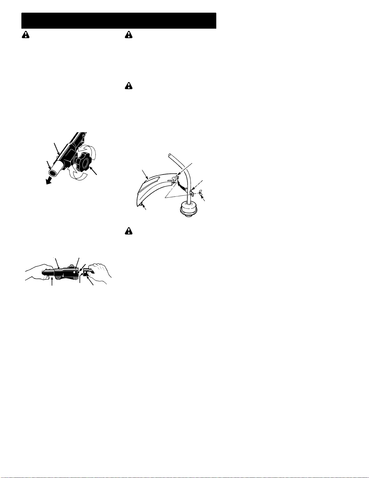
SInstall required shield properly before using
the unit. Use only specified trimmer head;
make sure it is properly installed and se-
curely fastened.
SMake sure unit is assembled correctly as
shown in this manual.
SMake carburetor adjustments with lower
end supported to prevent line from contact-
ing any object.
SKeep others away when making carburetor
adjustments.
SUse only recommended Snappert/Weed
Eater"accessories and replacement
parts.
SHave all maintenance and service not ex-
plained in this manual performed by an au-
thorized service dealer.
FUEL SAFETY
SMix and pour fuel outdoors.
SKeep away from sparks or flames.
SUse a container approved for fuel.
SDo not smoke orallow smoking near fuel or
the unit.
SAvoid spilling fuel or oil. Wipe up all fuel
spills.
SMove at least 10 feet (3 meters) away from
fueling site before starting engine.
SStop engine and allow to cool before re-
moving fuel cap.
SAlways store gasoline in a container ap-
proved for flammable liquids.
TRANSPORTING AND STORAGE
SAllow engine tocool before storing or trans-
porting in vehicle.
SEmpty the fuel tank before storing or trans-
porting the unit. Use upfuel left in the carbu-
retor by starting the engine and letting it run
until it stops.
SStore unit and fuel in area where fuel vapors
cannot reach sparks or open flames fromwa-
ter heaters, electric motors or switches, fur-
naces, etc.
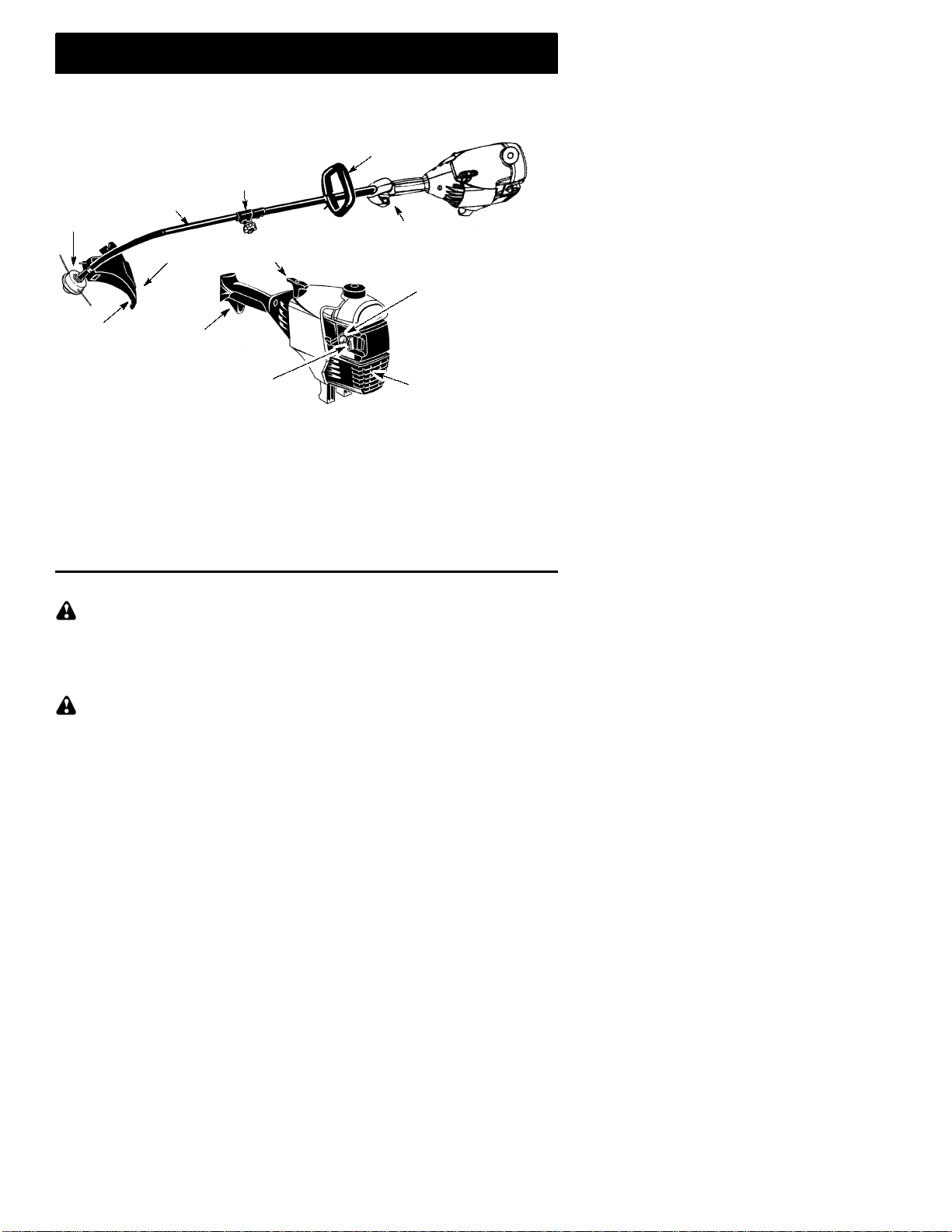
SStore unit so line limiter blade cannot acci-
dentally cause injury. The unit can be hung
by the tube.
SStore unit out of reach of children.
SAFETY NOTICE: Exposure to vibrations
through prolonged use of gasoline powered
hand tools could cause blood vessel ornerve
damage in the fingers, hands, and joints of
people prone to circulation disorders or ab-
normal swellings. Prolonged use in cold
weather hasbeenlinked toblood vessel dam-
age in otherwise healthy people. If symptoms
occur such as numbness, pain, loss of
strength, change in skin color or texture, or
loss of feeling in the fingers, hands, or joints,
discontinue the use of this tool and seek med-
ical attention. An anti--vibration system does
not guarantee the avoidance of these prob-
lems. Users who operate power tools on a
continual and regular basis must monitor
closely their physical condition and the condi-
tion of this tool.
SPECIAL NOTICE: This unit is equipped
with a temperature limiting muffler and spark
arresting screen which meets the require-
ments of California Codes 4442 and 4443. All
U.S. forest land and the states of California,
Idaho, Maine, Minnesota, New Jersey, Ore-
gon, and Washington require by law that
many internal combustion engines be
equipped with asparkarresting screen. Ifyou
operate in alocale where such regulations ex-
ist, youarelegally responsible formaintaining
the operating condition of these parts. Failure
to do so is a violation of the law. For normal
homeowner use, the mufflerand spark arrest-
ing screen will not require any service. After
50 hours of use, we recommend that your
muffler be serviced or replaced by an autho-
rized service dealer.
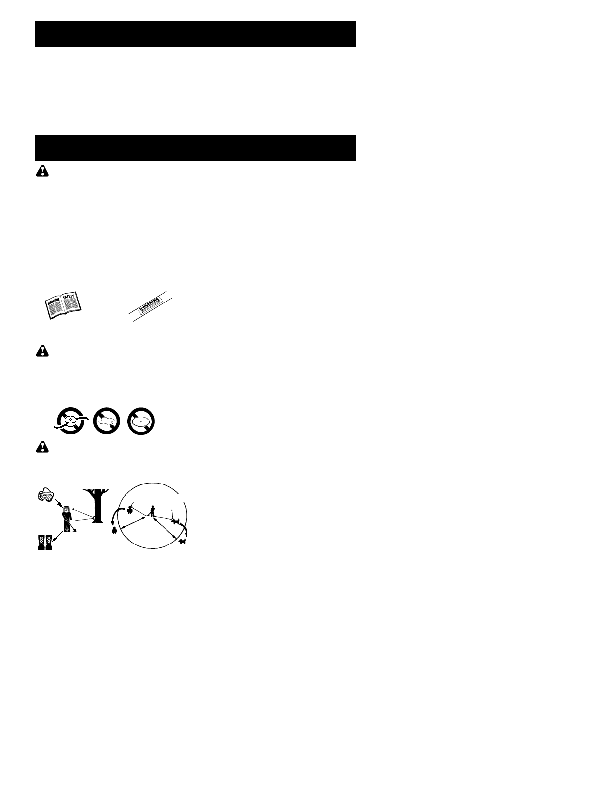
LINE TRIMMER SAFETY
WARNING: Inspect the area to be
trimmed before each use. Remove objects
(rocks, broken glass, nails, wire, etc.) which
can bethrown byorbecome entangled inline.
Hard objects can damage the trimmer head
and be thrown causing serious injury.
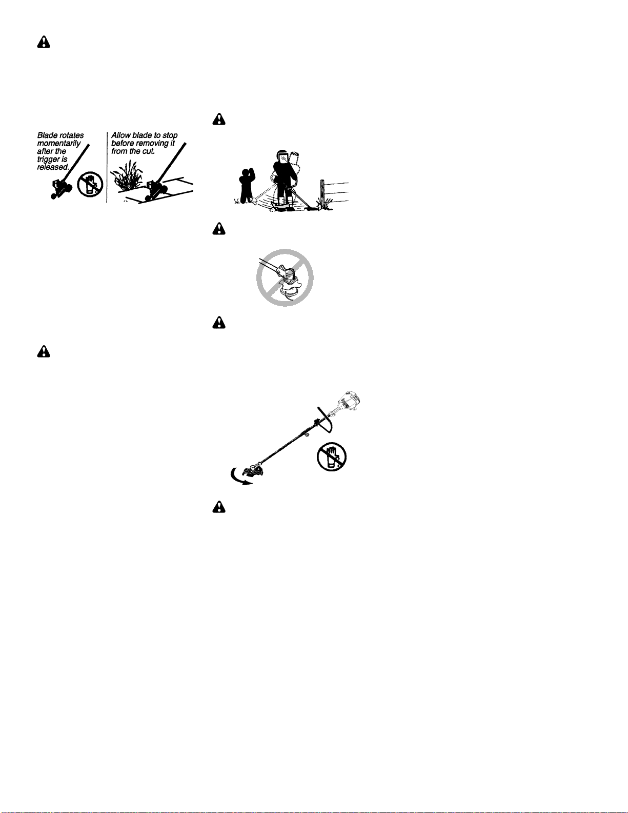
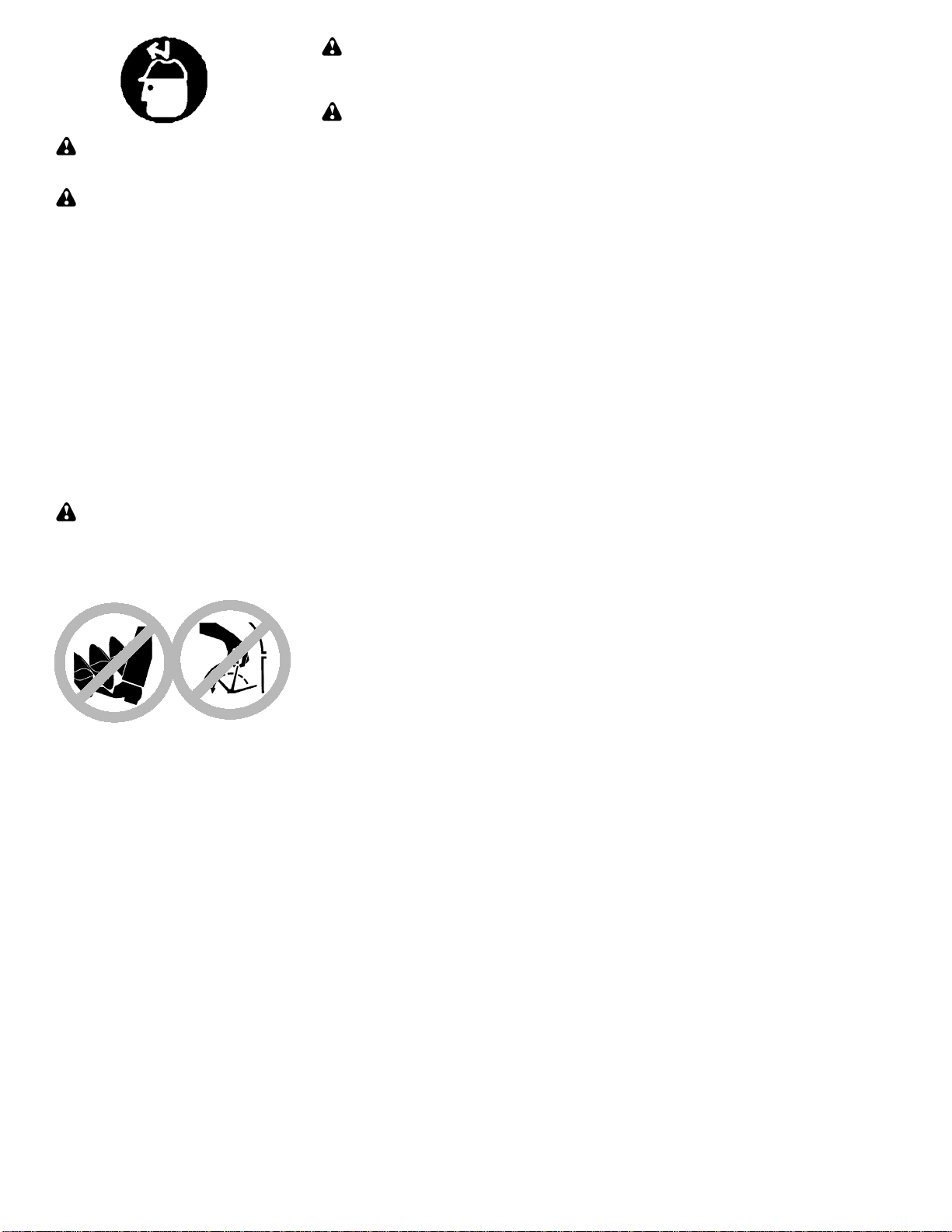
SUse only for trimming, scalping, mowing and
sweeping. Do not use for edging, pruning or
hedge trimming.
SCut from your right to your left. Cutting on
left side of the shield will throw debris away
from the operator.
ADDITIONAL SAFETY RULES
FOR OPTIONAL ATTACHMENTS
WARNING: For each optional at-
tachment used, read entire instruction manu-
al before use and follow all warnings and in-
structions in manual and on attachment.
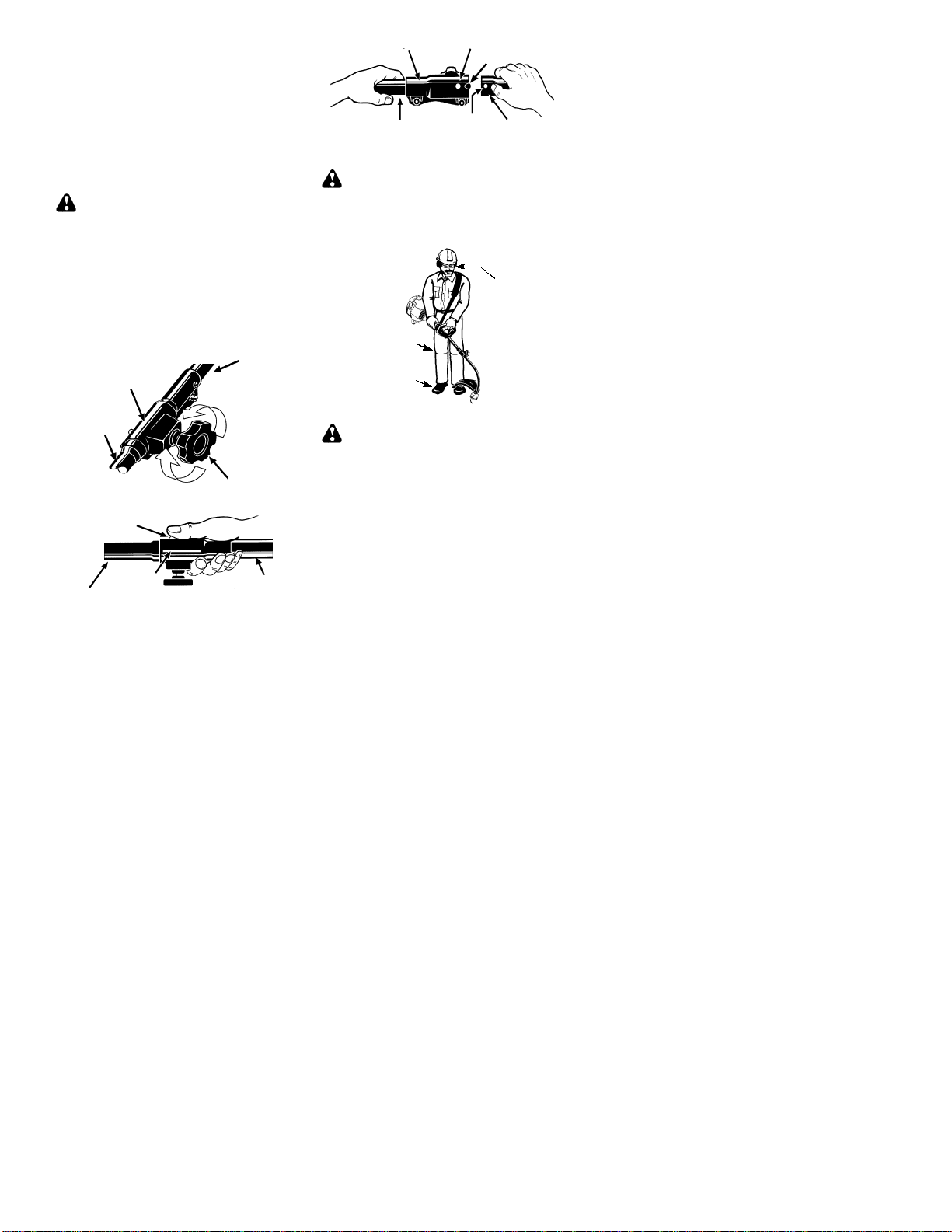
WARNING: Ensure handlebar is
installed when using edger or brushcutter at-
tachments. Attach handlebar above arrowon
safety label on the upper tube (engine end of
unit). If your edger or brushcutter attachment
does not include a handlebar,ahandlebar ac-
cessory kit (#530071451) is available from
your authorized service dealer.
Handlebar
For Parts Call K&T 606-678-9623 or 606-561-4983
www.mymowerparts.com