Snell IQSYN21 Operator's manual

snellgroup.com
User Instruction Manual
IQSYN21
HD/SD-SDI Frame Synchronizer with Embedded Audio Processing

IQSYN21 www.snellgroup.com Information and Notices
Issue 2 Rev 2 Page 2 ©2014 Snell Limited
Information and Notices
Copyright and Disclaimer
Copyright protection claimed includes all forms and matters of copyrightable material and
information now allowed by statutory or judicial law or hereinafter granted, including without
limitation, material generated from the software programs which are displayed on the screen
such as icons, screen display looks etc.
Information in this manual and software are subject to change without notice and does not
represent a commitment on the part of Snell Limited. The software described in this manual is
furnished under a license agreement and can not be reproduced or copied in any manner
without prior agreement with Snell Limited. or their authorized agents.
Reproduction or disassembly of embedded computer programs or algorithms prohibited.
No part of this publication can be transmitted or reproduced in any form or by any means,
electronic or mechanical, including photocopy, recording or any information storage and
retrieval system, without permission being granted, in writing, by the publishers or their
authorized agents.
Snell operates a policy of continuous improvement and development. Snell reserves the right
to make changes and improvements to any of the products described in this document
without prior notice.
Contact Details
Customer Support
For further details of our Regional Customer Support Offices, please visit the Snell website
and navigate to Support/Customer Support Contacts.
http://www.snellgroup.com/support/customer-support/customer-support/
Customers with a support contract should call their personalized number, which can be found
in their contract, and be ready to provide their contract number and details.
United Kingdom (HQ)
+44 (0) 118 921 4214 (tel)
+44 (0) 118 921 4268 (fax)
Regional Support Contacts
Snell USA
+1 818 556 2616 (tel)
+1 818 556 2626 (fax)
Snell Germany
+49 (0) 6122 98 43 0 (tel)
+49 (0) 6122 98 43 44 (fax)
Snell Spain
+34 91 446 23 07 (tel)
+34 91 446 17 74 (fax)
Snell France
+33 1 41 95 30 50 (tel)
+33 1 41 95 30 51 (fax)
Snell Asia Pacific
+852 2356 1660 (tel)
+852 2575 1690 (fax)
Snell India
+91 124 462 6000 (tel)
+91 124 437 5888 (fax)
Snell Russia
+7 499 248 3443 (tel)
+7 499 248 1104 (fax)
Snell China
+86 10 6515 6158 (tel)
+86 10 6515 5659 (fax)

IQSYN21 www.snellgroup.com Contents
Issue 2 Rev 2 Page 3 ©2014 Snell Limited
Contents
Information and Notices . . . . . . . . . . . . . . . . . . . . . . . . . . . . . . . . . . . . . . . . . . . . . . . . 2
1. Introduction. . . . . . . . . . . . . . . . . . . . . . . . . . . . . . . . . . . . . . . . . . . . . . . . . . . . . . . . . 6
1.1 Module Description . . . . . . . . . . . . . . . . . . . . . . . . . . . . . . . . . . . . . . . . . . . . . . . . 6
1.2 Order Codes . . . . . . . . . . . . . . . . . . . . . . . . . . . . . . . . . . . . . . . . . . . . . . . . . . . . . 7
1.3 Rear Panel View . . . . . . . . . . . . . . . . . . . . . . . . . . . . . . . . . . . . . . . . . . . . . . . . . . 8
1.4 Enclosures. . . . . . . . . . . . . . . . . . . . . . . . . . . . . . . . . . . . . . . . . . . . . . . . . . . . . . . 9
1.4.1 B-style Enclosure . . . . . . . . . . . . . . . . . . . . . . . . . . . . . . . . . . . . . . . . . . . 9
1.4.2 A-style Enclosures . . . . . . . . . . . . . . . . . . . . . . . . . . . . . . . . . . . . . . . . . . 9
1.5 Features . . . . . . . . . . . . . . . . . . . . . . . . . . . . . . . . . . . . . . . . . . . . . . . . . . . . . . . 10
2. Technical Specification . . . . . . . . . . . . . . . . . . . . . . . . . . . . . . . . . . . . . . . . . . . . . . 11
3. Connections . . . . . . . . . . . . . . . . . . . . . . . . . . . . . . . . . . . . . . . . . . . . . . . . . . . . . . . 14
3.1 IQSYN2126-1A / IQSYN2127-2A / IQSYN2139-2A . . . . . . . . . . . . . . . . . . . . . . 14
3.1.1 SDI Inputs . . . . . . . . . . . . . . . . . . . . . . . . . . . . . . . . . . . . . . . . . . . . . . . 14
3.1.2 SDI Outputs . . . . . . . . . . . . . . . . . . . . . . . . . . . . . . . . . . . . . . . . . . . . . . 14
3.1.3 Analog Reference Input . . . . . . . . . . . . . . . . . . . . . . . . . . . . . . . . . . . . . 14
3.1.4 GPI . . . . . . . . . . . . . . . . . . . . . . . . . . . . . . . . . . . . . . . . . . . . . . . . . . . . . 14
4. Card Edge LEDs . . . . . . . . . . . . . . . . . . . . . . . . . . . . . . . . . . . . . . . . . . . . . . . . . . . . 15
5. Controlling the IQSYN21 from the RollCall Control Panel . . . . . . . . . . . . . . . . . . 16
5.1 The Information Window . . . . . . . . . . . . . . . . . . . . . . . . . . . . . . . . . . . . . . . . . . . 16
5.1.1 Video Status. . . . . . . . . . . . . . . . . . . . . . . . . . . . . . . . . . . . . . . . . . . . . . 16
5.1.2 Audio Status . . . . . . . . . . . . . . . . . . . . . . . . . . . . . . . . . . . . . . . . . . . . . . 17
5.2 Video Input . . . . . . . . . . . . . . . . . . . . . . . . . . . . . . . . . . . . . . . . . . . . . . . . . . . . . 18
5.2.1 Input Select . . . . . . . . . . . . . . . . . . . . . . . . . . . . . . . . . . . . . . . . . . . . . . 18
5.2.2 Input Backup . . . . . . . . . . . . . . . . . . . . . . . . . . . . . . . . . . . . . . . . . . . . . 18
5.2.3 Input Loss If . . . . . . . . . . . . . . . . . . . . . . . . . . . . . . . . . . . . . . . . . . . . . . 18
5.2.4 Agile V-Lock . . . . . . . . . . . . . . . . . . . . . . . . . . . . . . . . . . . . . . . . . . . . . . 19
5.2.5 Valid Input Standards . . . . . . . . . . . . . . . . . . . . . . . . . . . . . . . . . . . . . . . 19
5.2.6 CRC/EDH Errors . . . . . . . . . . . . . . . . . . . . . . . . . . . . . . . . . . . . . . . . . . 19
5.3 Input Backup . . . . . . . . . . . . . . . . . . . . . . . . . . . . . . . . . . . . . . . . . . . . . . . . . . . . 20
5.3.1 Enable Backup Input Switch . . . . . . . . . . . . . . . . . . . . . . . . . . . . . . . . . 20
5.3.2 Priority / Reversion. . . . . . . . . . . . . . . . . . . . . . . . . . . . . . . . . . . . . . . . . 20
5.3.3 Backup State Select. . . . . . . . . . . . . . . . . . . . . . . . . . . . . . . . . . . . . . . . 21
5.3.4 Master State Select . . . . . . . . . . . . . . . . . . . . . . . . . . . . . . . . . . . . . . . . 21
5.3.5 Input Select . . . . . . . . . . . . . . . . . . . . . . . . . . . . . . . . . . . . . . . . . . . . . . 21
5.3.6 Master (Inp 1) Carrier Detect Fail. . . . . . . . . . . . . . . . . . . . . . . . . . . . . . 21
5.3.7 Master (Inp 1) Invalid Standard . . . . . . . . . . . . . . . . . . . . . . . . . . . . . . . 21
5.3.8 Master (Inp 1) Error . . . . . . . . . . . . . . . . . . . . . . . . . . . . . . . . . . . . . . . . 22
5.3.9 Master (Inp 1) Embedded Audio Fail . . . . . . . . . . . . . . . . . . . . . . . . . . . 22
5.3.10 Backup (Inp 2) Carrier Detect Fail . . . . . . . . . . . . . . . . . . . . . . . . . . . . 22
5.4 Video Output . . . . . . . . . . . . . . . . . . . . . . . . . . . . . . . . . . . . . . . . . . . . . . . . . . . . 23
5.4.1 Output . . . . . . . . . . . . . . . . . . . . . . . . . . . . . . . . . . . . . . . . . . . . . . . . . . 23
5.4.2 Output Standard. . . . . . . . . . . . . . . . . . . . . . . . . . . . . . . . . . . . . . . . . . . 24
5.4.3 Pattern . . . . . . . . . . . . . . . . . . . . . . . . . . . . . . . . . . . . . . . . . . . . . . . . . . 24
5.4.4 Default Output . . . . . . . . . . . . . . . . . . . . . . . . . . . . . . . . . . . . . . . . . . . . 24
5.4.5 ProcAmp . . . . . . . . . . . . . . . . . . . . . . . . . . . . . . . . . . . . . . . . . . . . . . . . 25
5.4.6 Utilities . . . . . . . . . . . . . . . . . . . . . . . . . . . . . . . . . . . . . . . . . . . . . . . . . . 25
5.5 Embedded Proc Amp Groups 1-2 and 3-4 . . . . . . . . . . . . . . . . . . . . . . . . . . . . . 26
5.5.1 Groups 1 to 4, Pairs 1 and 2 (Embed 1-8 L & R) . . . . . . . . . . . . . . . . . . 26
5.6 Audio Mixer 1-4 . . . . . . . . . . . . . . . . . . . . . . . . . . . . . . . . . . . . . . . . . . . . . . . . . . 27
5.6.1 Audio Sources . . . . . . . . . . . . . . . . . . . . . . . . . . . . . . . . . . . . . . . . . . . . 27
5.6.2 Mixer . . . . . . . . . . . . . . . . . . . . . . . . . . . . . . . . . . . . . . . . . . . . . . . . . . . 27
5.7 Embedded Routing Groups 1-2 and 3-4 . . . . . . . . . . . . . . . . . . . . . . . . . . . . . . . 28

IQSYN21 www.snellgroup.com Contents
Issue 2 Rev 2 Page 4 ©2014 Snell Limited
5.7.1 Link L+R . . . . . . . . . . . . . . . . . . . . . . . . . . . . . . . . . . . . . . . . . . . . . . . . . 28
5.8 Embed On/Off . . . . . . . . . . . . . . . . . . . . . . . . . . . . . . . . . . . . . . . . . . . . . . . . . . . 29
5.8.1 Embedder Priority . . . . . . . . . . . . . . . . . . . . . . . . . . . . . . . . . . . . . . . . . 29
5.8.2 Group/Channel Active . . . . . . . . . . . . . . . . . . . . . . . . . . . . . . . . . . . . . . 29
5.9 Embedded I/P Setup . . . . . . . . . . . . . . . . . . . . . . . . . . . . . . . . . . . . . . . . . . . . . . 30
5.9.1 Embedded Audio Input Names . . . . . . . . . . . . . . . . . . . . . . . . . . . . . . . 30
5.10 Embedded O/P Setup . . . . . . . . . . . . . . . . . . . . . . . . . . . . . . . . . . . . . . . . . . . . 32
5.10.1 Embedded Audio Output Names . . . . . . . . . . . . . . . . . . . . . . . . . . . . . 32
5.11 Video Delay/DolbyE/Genlock. . . . . . . . . . . . . . . . . . . . . . . . . . . . . . . . . . . . . . . 33
5.11.1 Genlock . . . . . . . . . . . . . . . . . . . . . . . . . . . . . . . . . . . . . . . . . . . . . . . . 34
5.11.2 Delay Timing. . . . . . . . . . . . . . . . . . . . . . . . . . . . . . . . . . . . . . . . . . . . . 35
5.11.3 Dolby E Timing . . . . . . . . . . . . . . . . . . . . . . . . . . . . . . . . . . . . . . . . . . . 35
5.11.4 Dolby E Auto Line . . . . . . . . . . . . . . . . . . . . . . . . . . . . . . . . . . . . . . . . . 36
5.12 Audio Delays . . . . . . . . . . . . . . . . . . . . . . . . . . . . . . . . . . . . . . . . . . . . . . . . . . . 37
5.12.1 Audio Delay Select - A/B . . . . . . . . . . . . . . . . . . . . . . . . . . . . . . . . . . . 38
5.12.2 Internal Video Delay. . . . . . . . . . . . . . . . . . . . . . . . . . . . . . . . . . . . . . . 38
5.12.3 Smooth Delay Limit . . . . . . . . . . . . . . . . . . . . . . . . . . . . . . . . . . . . . . . 38
5.12.4 Embed Delay 1 to 8 . . . . . . . . . . . . . . . . . . . . . . . . . . . . . . . . . . . . . . . 39
5.12.5 Reliable Audio Alignment - Use Cases. . . . . . . . . . . . . . . . . . . . . . . . . 39
5.13 ANC Blank & Bridge . . . . . . . . . . . . . . . . . . . . . . . . . . . . . . . . . . . . . . . . . . . . . 41
5.13.1 VBI for Standard. . . . . . . . . . . . . . . . . . . . . . . . . . . . . . . . . . . . . . . . . . 41
5.13.2 Blank Lines. . . . . . . . . . . . . . . . . . . . . . . . . . . . . . . . . . . . . . . . . . . . . . 42
5.13.3 Input Ancillary. . . . . . . . . . . . . . . . . . . . . . . . . . . . . . . . . . . . . . . . . . . . 42
5.13.4 Ancillary Bridge . . . . . . . . . . . . . . . . . . . . . . . . . . . . . . . . . . . . . . . . . . 42
5.14 GPIO . . . . . . . . . . . . . . . . . . . . . . . . . . . . . . . . . . . . . . . . . . . . . . . . . . . . . . . . . 43
5.14.1 GPIO 1 and GPIO 2 . . . . . . . . . . . . . . . . . . . . . . . . . . . . . . . . . . . . . . . 43
5.14.2 GPI 1 (Input) or GPI 2 (Input). . . . . . . . . . . . . . . . . . . . . . . . . . . . . . . . 43
5.14.3 GPI 1 (Output) and GPI 2 (Output) . . . . . . . . . . . . . . . . . . . . . . . . . . . 44
5.14.4 GPIO Input Pulse Width Timer . . . . . . . . . . . . . . . . . . . . . . . . . . . . . . . 44
5.14.5 GPIO Interface Circuitry . . . . . . . . . . . . . . . . . . . . . . . . . . . . . . . . . . . . 45
5.15 Memory . . . . . . . . . . . . . . . . . . . . . . . . . . . . . . . . . . . . . . . . . . . . . . . . . . . . . . . 46
5.15.1 Recall Memory . . . . . . . . . . . . . . . . . . . . . . . . . . . . . . . . . . . . . . . . . . . 46
5.15.2 Save Memory . . . . . . . . . . . . . . . . . . . . . . . . . . . . . . . . . . . . . . . . . . . . 46
5.15.3 Last Recalled . . . . . . . . . . . . . . . . . . . . . . . . . . . . . . . . . . . . . . . . . . . . 46
5.15.4 Save Memory Name . . . . . . . . . . . . . . . . . . . . . . . . . . . . . . . . . . . . . . 47
5.16 RollTrack . . . . . . . . . . . . . . . . . . . . . . . . . . . . . . . . . . . . . . . . . . . . . . . . . . . . . . 48
5.16.1 Disable All . . . . . . . . . . . . . . . . . . . . . . . . . . . . . . . . . . . . . . . . . . . . . . 48
5.16.2 RollTrack Index . . . . . . . . . . . . . . . . . . . . . . . . . . . . . . . . . . . . . . . . . . 48
5.16.3 RollTrack Source . . . . . . . . . . . . . . . . . . . . . . . . . . . . . . . . . . . . . . . . . 48
5.16.4 RollTrack Address . . . . . . . . . . . . . . . . . . . . . . . . . . . . . . . . . . . . . . . . 49
5.16.5 RollTrack Command. . . . . . . . . . . . . . . . . . . . . . . . . . . . . . . . . . . . . . . 49
5.16.6 RollTrack Sending . . . . . . . . . . . . . . . . . . . . . . . . . . . . . . . . . . . . . . . . 50
5.16.7 RollTrack Status . . . . . . . . . . . . . . . . . . . . . . . . . . . . . . . . . . . . . . . . . . 50
5.17 Logging . . . . . . . . . . . . . . . . . . . . . . . . . . . . . . . . . . . . . . . . . . . . . . . . . . . . . . . 51
5.17.1 Video Input Logging . . . . . . . . . . . . . . . . . . . . . . . . . . . . . . . . . . . . . . . 51
5.17.2 In1/2 Aud State Logging. . . . . . . . . . . . . . . . . . . . . . . . . . . . . . . . . . . . 51
5.17.3 In1/2 Aud Type Logging . . . . . . . . . . . . . . . . . . . . . . . . . . . . . . . . . . . . 52
5.17.4 O/P Aud Level Logging . . . . . . . . . . . . . . . . . . . . . . . . . . . . . . . . . . . . 52
5.17.5 O/P Aud State Logging. . . . . . . . . . . . . . . . . . . . . . . . . . . . . . . . . . . . . 53
5.17.6 O/P Aud Type Logging . . . . . . . . . . . . . . . . . . . . . . . . . . . . . . . . . . . . . 53
5.17.7 O/P Dolby ELogging. . . . . . . . . . . . . . . . . . . . . . . . . . . . . . . . . . . . . . . 53
5.17.8 Ref/Output Logging . . . . . . . . . . . . . . . . . . . . . . . . . . . . . . . . . . . . . . . 54
5.17.9 Misc. Logging . . . . . . . . . . . . . . . . . . . . . . . . . . . . . . . . . . . . . . . . . . . . 54
5.17.10 Log Field Descriptions . . . . . . . . . . . . . . . . . . . . . . . . . . . . . . . . . . . . 55
5.18 Setup . . . . . . . . . . . . . . . . . . . . . . . . . . . . . . . . . . . . . . . . . . . . . . . . . . . . . . . . . 57
5.18.1 Default Settings . . . . . . . . . . . . . . . . . . . . . . . . . . . . . . . . . . . . . . . . . . 57
5.18.2 Factory Defaults . . . . . . . . . . . . . . . . . . . . . . . . . . . . . . . . . . . . . . . . . . 57
5.18.3 Restart . . . . . . . . . . . . . . . . . . . . . . . . . . . . . . . . . . . . . . . . . . . . . . . . . 57
Appendix A. RollTrack Audio Delay Tracking . . . . . . . . . . . . . . . . . . . . . . . . . . . . . . 58

IQSYN21 www.snellgroup.com Contents
Issue 2 Rev 2 Page 5 ©2014 Snell Limited
A.1 Introduction . . . . . . . . . . . . . . . . . . . . . . . . . . . . . . . . . . . . . . . . . . . . . . . . . . . . . 58
A.2 Configuration: Single Video Unit and Single Audio Delay. . . . . . . . . . . . . . . . . . 58
A.3 Configuration: Multiple Video Units and Audio Delays . . . . . . . . . . . . . . . . . . . . 58
A.4 Configuration: Vertical Delay Cluster . . . . . . . . . . . . . . . . . . . . . . . . . . . . . . . . . 59
A.5 Configuration: Horizontal Delay Cluster . . . . . . . . . . . . . . . . . . . . . . . . . . . . . . . 59
A.6 Configuration: Matrix Delay Cluster . . . . . . . . . . . . . . . . . . . . . . . . . . . . . . . . . . 60
A.7 Connecting up a Audio Delay Tracking. . . . . . . . . . . . . . . . . . . . . . . . . . . . . . . . 60
A.7.1 Configuration: An Array of Matrix Clusters . . . . . . . . . . . . . . . . . . . . . . 62
Appendix B. Firewall . . . . . . . . . . . . . . . . . . . . . . . . . . . . . . . . . . . . . . . . . . . . . . . . . . 64
B.1 Introduction . . . . . . . . . . . . . . . . . . . . . . . . . . . . . . . . . . . . . . . . . . . . . . . . . . . . . 64
B.2 How a Firewall Equipped Product Behaves . . . . . . . . . . . . . . . . . . . . . . . . . . . . 64
B.3 Why Use a Firewall? . . . . . . . . . . . . . . . . . . . . . . . . . . . . . . . . . . . . . . . . . . . . . . 64
B.3.1 Using a Firewall at the Beginning of a Chain. . . . . . . . . . . . . . . . . . . . . 64
B.3.2 Using a Firewall to Protect MPEG Encoders . . . . . . . . . . . . . . . . . . . . . 64
B.4 How a Firewall is Tested. . . . . . . . . . . . . . . . . . . . . . . . . . . . . . . . . . . . . . . . . . . 64
B.5 Performance of Firewall Equipped Products Versus Genlock Mode . . . . . . . . . 65
B.6 When Firewall Protection is Not Provided. . . . . . . . . . . . . . . . . . . . . . . . . . . . . . 65
B.6.1 Video . . . . . . . . . . . . . . . . . . . . . . . . . . . . . . . . . . . . . . . . . . . . . . . . . . . 65
B.6.2 Audio . . . . . . . . . . . . . . . . . . . . . . . . . . . . . . . . . . . . . . . . . . . . . . . . . . . 65
Appendix C. Ancillary Passing . . . . . . . . . . . . . . . . . . . . . . . . . . . . . . . . . . . . . . . . . . 66
C.1 SMPTE 272M and 299M . . . . . . . . . . . . . . . . . . . . . . . . . . . . . . . . . . . . . . . . . . 66
C.2 SMPTE 291M . . . . . . . . . . . . . . . . . . . . . . . . . . . . . . . . . . . . . . . . . . . . . . . . . . . 66
Appendix D. Audio Processing Overview . . . . . . . . . . . . . . . . . . . . . . . . . . . . . . . . . 68
D.1 Audio Processing Block Diagram . . . . . . . . . . . . . . . . . . . . . . . . . . . . . . . . . . . . 68
D.2 Audio Processing – Control Panel Screens Associations. . . . . . . . . . . . . . . . . . 68
D.3 SDI Demultiplexer. . . . . . . . . . . . . . . . . . . . . . . . . . . . . . . . . . . . . . . . . . . . . . . . 69
D.4 Audio Delay Processor . . . . . . . . . . . . . . . . . . . . . . . . . . . . . . . . . . . . . . . . . . . . 70
D.5 Tone Generator . . . . . . . . . . . . . . . . . . . . . . . . . . . . . . . . . . . . . . . . . . . . . . . . . 71
D.6 Mixers 1 to 4 . . . . . . . . . . . . . . . . . . . . . . . . . . . . . . . . . . . . . . . . . . . . . . . . . . . . 72
D.7 Embedder ProcAmps . . . . . . . . . . . . . . . . . . . . . . . . . . . . . . . . . . . . . . . . . . . . . 72
D.8 SDI TX . . . . . . . . . . . . . . . . . . . . . . . . . . . . . . . . . . . . . . . . . . . . . . . . . . . . . . . . 73
D.9 Dolby E Audio Handling . . . . . . . . . . . . . . . . . . . . . . . . . . . . . . . . . . . . . . . . . . . 73
Appendix E. Dolby E . . . . . . . . . . . . . . . . . . . . . . . . . . . . . . . . . . . . . . . . . . . . . . . . . . 74
E.1 What is Dolby E? . . . . . . . . . . . . . . . . . . . . . . . . . . . . . . . . . . . . . . . . . . . . . . . . 74
E.2 Dolby E and Metadata . . . . . . . . . . . . . . . . . . . . . . . . . . . . . . . . . . . . . . . . . . . . 74
E.3 Dolby E Partner Program . . . . . . . . . . . . . . . . . . . . . . . . . . . . . . . . . . . . . . . . . . 74
E.4 16- and 20-bit Dolby E . . . . . . . . . . . . . . . . . . . . . . . . . . . . . . . . . . . . . . . . . . . . 74
E.5 Dolby Digital and AC3. . . . . . . . . . . . . . . . . . . . . . . . . . . . . . . . . . . . . . . . . . . . . 75
E.6 Metadata . . . . . . . . . . . . . . . . . . . . . . . . . . . . . . . . . . . . . . . . . . . . . . . . . . . . . . . 75

IQSYN21 www.snellgroup.com Introduction
Issue 2 Rev 2 Page 6 ©2014 Snell Limited
1. Introduction
1.1 Module Description
The IQSYN21 provides synchronization for HD-SDI 1.5 Gbps or SD-SDI 270 Mbps signals
with 16-channel embedded audio processing including automatic synchronization of Dolby E
signals. Using agile synchronization that is router-switching-tolerant makes this module ideal
for all HD/SD-SDI lines input applications. A video processing amplifier provides complete
control over the video levels, and audio processing features include automatic Dolby E
re-alignment, PCM tracking audio delay, channel level routing and mixing. The IQSYN21 is
also able to directly pass audio channel status information to handle upstream switching of
SDI containing PCM and Dolby E embedded audio.
The IQSYN21's flexibility in its rate-agile HD and SD support means that 16, 20 and 24-bit
audio sources can all be handled. PCM audio can be processed alongside Dolby E and other
non-PCM signals with selection made on a pair-by-pair basis. Internally, the PCM audio is
treated as separate channels allowing stereo, mono and discrete surround-sound operation
as well as multi-lingual working. Any input PCM audio channel (not just pair) can be routed to
any output channel.
The sophisticated audio processing features include comprehensive audio delays, gain
control, phase inversion and mixing.
The module is fully Dolby E compatible and can handle other non-PCM audio streams
including Dolby AC3 (Dolby Digital) passed as AES data.
Unlike other audio processing modules, these units also have dedicated video control
features that include video processing amplifier controls and up to 11 frames of video delay.
The video delay can work in conjunction with the sophisticated delay features available for the
audio channels. Delay can be inserted in the video path to compensate for audio processing.
It can also be inserted in the audio path to compensate for video processing. It can be
inserted in both to simply re-time the complete signal.

IQSYN21 www.snellgroup.com Introduction
Issue 2 Rev 2 Page 7 ©2014 Snell Limited
1.2 Order Codes
The following product order codes are covered by this manual:
IQSYN2126-1A HD-SDI and SD-SDI Synchronizer with Embedded Audio
Processing. 3 outputs, 1 GPI.
IQSYN2127-2A HD-SDI and SD-SDI Synchronizer with Embedded Audio
Processing. 4 outputs, 2 GPIs.
IQSYN2139-2A HD-SDI and SD-SDI Synchronizer with Embedded Audio Processing
and relay input bypass. 4 outputs, 2 GPIs.
IQSYN21 www.snellgroup.com Introduction
Issue 2 Rev 2 Page 8 ©2014 Snell Limited
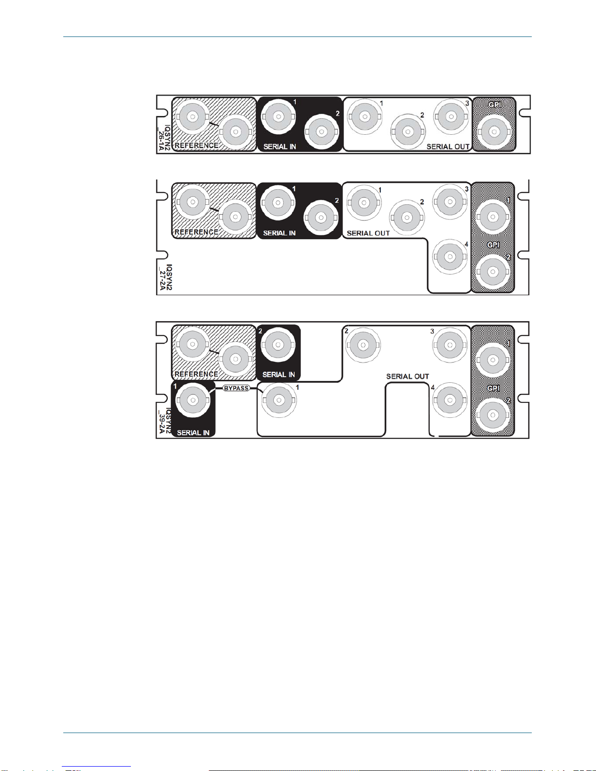
1.3 Rear Panel View
The following rear panel types are available:
IQSYN2126-1A
IQSYN2127-2A
IQSYN2139-2A
IQSYN21 www.snellgroup.com Introduction
Issue 2 Rev 2 Page 9 ©2014 Snell Limited
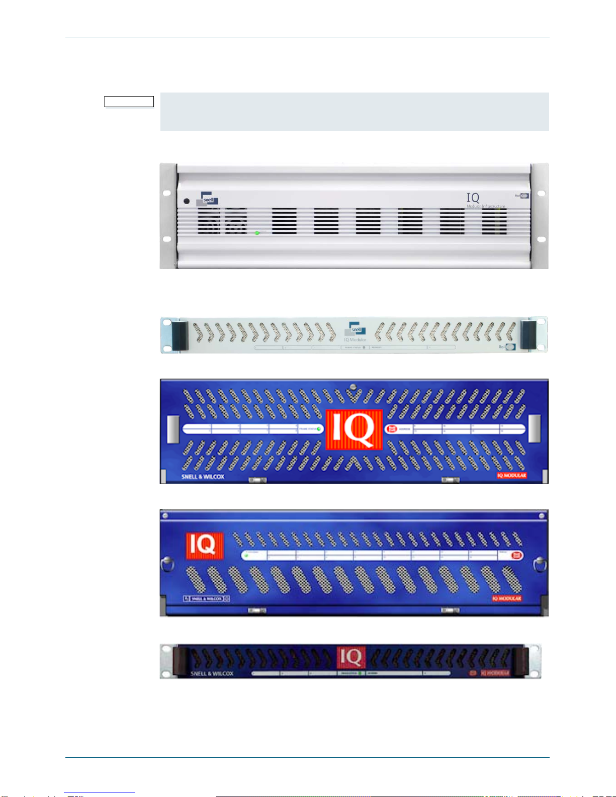
1.4 Enclosures
The module can be fitted into the enclosure types shown.
1.4.1 B-style Enclosure
Enclosure order codes: IQH3B-S-0, IQH3B-S-P
1.4.2 A-style Enclosures
Enclosure order code: IQH1A-S-P
Enclosure order codes: IQH3A-S-0, IQH3A-S-P
Enclosure order codes: IQH3A-E-0, IQH3A-E-P, IQH3A-0-0, IQH3A-0-P
Enclosure order code: IQH1A-S-P
Important: Although IQ modules are interchangeable between enclosures, their rear panels are
enclosure specific. An IQH3B enclosure accepts modules with either “A” or “B” order
codes. An IQH3A or IQH1A enclosure accepts modules with “A” order codes only.

IQSYN21 www.snellgroup.com Introduction
Issue 2 Rev 2 Page 10 ©2014 Snell Limited
1.5 Features
• Agile HD/SD-SDI synchronizer with up to 11 frames of video delay and tracking audio
delay
• Handles up to 16 channels of embedded audio present on the incoming SDI stream
including ancillary cleaner for removal of unused ancillary data
• Embedded Dolby E support – pair routing and automatic re-alignment and
synchronization to the video frame boundary
• Dual selectable HD/SD-SDI inputs with auto switching
• Agile synchronizer locking capable of handling mis-timed inputs of up to 5 lines
without output video disturbance (SMPTE RP168 compliant)
• Standards supported:
• HD-SDI to SMPTE 292M/274M/296M
• SD-SDI to SMPTE 259M-C
• Capable of referencing to a bi-level or tri-level reference for HD timing
• Precision wide range genlock adjustment allowing you to time any HD/SD-SDI
signal to pixel accuracy
• Independent horizontal and vertical ancillary data blanking
• Tracking audio delay which seamlessly tracks the internal video delay and external
RollTrack or GPI inputs
• 2 independent audio delay controllers including selectable fixed delay and
RollTrack/GPI tracking delays for each (either selectable for eight pairs)
• Any group of embedded audio may be passed unchanged if not selected for
processing or blanked
• Channel level (Sub-frame) routing
• 4 off 4 channel assignable audio mixers
• Audio processing amplifier and delay
• Built in Dolby E timing monitor allows accurate manual adjustment of Dolby E guard
band position
• Input loss detection – input pass through/switch or black/pattern/freeze and
• Input SDI, CRC, EDH and ANC data checking and reporting
• Emergency input bypass option enables the SDI input signal to be passed through to
SDI output 1 in the event of frame power failure or module removal
• Can be used as a video delay without synchronization, up to 11 frames
• Video processing controls including video gain and offset
• In-built test pattern generator
• 16x user memories

IQSYN21 www.snellgroup.com Technical Specification
Issue 2 Rev 2 Page 11 ©2014 Snell Limited
2. Technical Specification
Inputs and Outputs
Signal Inputs
SDI Inputs 2x HD/SD-SDI
Electrical 1.5 Gbps HD-SDI, SMPTE 292M 270 Mbps SDSDI, SMPTE 259M-C
Connector / Format BNC / 75 Ohm panel jack on standard Snell connector panel
Input Cable Length Up to 140 m Belden 1694A @ 1.5 Gbps (40 m input cable length and
35 m output cable length, relay bypass version. Belden 1694A @
1.5 Gbps)
Up to 275 m Belden 1694A @ 270 Mbps
Note: Specified cable lengths are a guide only. Exact cable length performance will depend on the quality of the
cable used, the SDI video rate and the system setup. It is advisable not to cascade modules using the relay rear
version although it may be possible if the interconnecting cable lengths are kept to an absolute minimum.
Return Loss >-15 dB
Relay Bypass Versions
Input Return Loss >-8 dB (When not in BYPASS mode)
Output Return Loss >-8 dB (When not in BYPASS mode)
Reference Input
Analog Reference Input 1 x Analog Reference with passive loop-through SMPTE 240/ 274M and
RS170A
Electrical Black (HD tri-level and SD bi-level) and Black Burst (SD bi-level)
SD bi-level – RS170A, HD tri-level – SMPTE 240M, 274M and 296M
Connector / Format BNC / 75 Ohm panel jack on standard Snell connector panel
Analog Reference Return Loss SD bi-level > -40 dB to 5.5 MHz
HD tri-level > -35 dB to 30 MHz
Signal Outputs
SDI Outputs 3x / 4x HD/SD-SDI
Electrical 1.5 Gbps HD-SDI, SMPTE 292M 270 Mbps SDSDI, SMPTE 259M-C
Connector/Format BNC / 75 Ohm panel jack on standard Snell connector panel
Return Loss >-15 dB
Control Interface
GPI Up to 2x GPI (I/O configurable)
Electrical TTL-compatible, active-low driven
Connector / Format BNC / 75 Ohm panel jack on standard Snell connector panel
Controls
Indicators
Power OK (Green)
CPU Running OK (Green flashing)
FPGA Running OK (Yellow flashing)
Status OK (Green), Warning (Yellow), Error (Red)
Input 1 OK (Green), Loss (Off)
Input 2 OK (Green), Loss (Off)
SDI Err Error (Red)
Reference Lock OK (Green)
Video Controls

IQSYN21 www.snellgroup.com Technical Specification
Issue 2 Rev 2 Page 12 ©2014 Snell Limited
Select Primary Input 1 / 2 / Auto with user configurable rules
Output Standard Select, Follow Input, Follow Reference
Standards List Select video standards for automatic follow
Black Level ±200 mV in steps of 1 mV
Master Video Gain ±6 dB in steps of 0.1 dB
Y Gain ±6 dB in steps of 0.1 dB
Cb/Cr Gain ±6 dB in steps of 0.1 dB
Pattern Select 100% Color Bars, 75% Color Bars, SMPTE Bars, Tartan Bars, Black
Field, Pluge Ramp, H Sweep, Pulse and Bar, Burst
Blank Ancillary Data Blank All, Blank HANC, Pass All, Pass when Output Standard equals
Input Standard
VBI Line Blank Individual lines for each video standard
Manual Freeze On/Off
Freeze Field/Frame
Video Channel Control Mono, Y/C blank
Reference Select External with phasing, Input Video with delay (Units: Lines and Pixels),
Free-run
Delay Timing Delay Frames
Default Video Output Pattern / freeze / black / run through / redundant input
Auto Backup Rules 5 rules with Video presence and standard, Video Errors, Audio presence,
GPI actions and Time Delays
Audio Controls
Embedded Audio Types PCM (to AES3)/Data (SMPTE 337M inc. Dolby E)/Mixed (Passes any
channel status information present)
Channel Routing Output channels routed from SDI (16 embedded channels from any
group), test tone and silence
Output Side Control Proc.- Gain and
Polarity
Independent Gain, Mute, and Polarity control over embedded output
channels. +12 dB to -36 dB in 0.1 dB steps
Coarse Manual Delay 1 and 2 Up to +2 s in 0.25 ms steps, common to any selected pairs
Fine Manual Delay 1 and 2 Up to +0.25 ms in 5 μs steps, common to any selected pairs
Dolby E Delay (Alignment) Auto/Manual
Variable Audio Delay 1 and 2 Up to 0.5 s from RollTrack + GPI Delay
Pair Based Delay Sources Selectable video synchronizer delay + delay control 1 or 2
Embedder Priority Normal distribution/audio prioritized
Embedded Group Pass/Blank/Embed
Dolby E Auto Line Selection Define Dolby E embed line for each video standard
Tone Setup 1 kHz, 2 kHz, 4 kHz, mute @ -20 dBFS or -18 dBFS
Other Controls
GPI Configuration Not Used, as an output, as an input, pulse width timer + invert
GPI Input Activates on contact closure: Freeze, Pattern, Black, Blank ANC, Mono Y
only, Mono CbCr only, Use I/P and Ext. reference, Select Input 1 / 2 and
Backup
GPI Output Produces an output for: Input 1 / 2 OK, Reference OK Freeze, Pattern,
Black, Monochrome, Input 2 Selected
User memories 16x Save / Recall / Rename
RollCall Features

IQSYN21 www.snellgroup.com Technical Specification
Issue 2 Rev 2 Page 13 ©2014 Snell Limited
Logging Input Status, ANC, EDH, CRC Errors and standard, Reference Status and
Standard Video output status and standard, Embedded audio input status
and type (pairs 1-8), Embedded Dolby E output timing status (pairs 1-8)
RollTrack Controls Source, Address, Command, Status, Sending
Roll Track Sources Internal or detected device states that trigger the sending of RollTracks:
Unused, Video Delay, Input Present /Input Loss, Reference OK / Loss,
Output Freeze / Unfreeze, In 1/2 Select, GPI1/2 High / Low / Inactive,
Embedded Audio Present/Loss (Pairs 1-8), Out (video standards)
Specifications
Video Standards 750(720)/60p, 1125(1080)/30i
750(720)/59p, 1125(1080)/30sF
750(720)/50p, 1125(1080)/29i
1125(1080)/30p, 1125(1080)/29sF
1125(1080)/29p, 1125(1080)/25i
1125(1080)/25p, 1125(1080)/25sF
1125(1080)/24p, 1125(1080)/24sF
1125(1080)/23p, 1125(1080)/23sF
1125(1035)/30i
1125(1035)/29i
525(480)/29i, 625(576)/25i
Minimum Delay 1 line
Video Delay 1 line to 1 frame + 1line (synchronizing)
1 line to 1 frame – 1 pixel (delay mode)
Synchronizer Hysteresis Window HD - 4 μs
SD - 11 μs
Reference Source External – HD tri-level (HD output only), SD bi-level, Input Video syncs
Genlock Adjustment Up to ±1 frame in steps of 1 pixel
Embedded Audio Handling HD - 24-bit synchronous 48 kHz to SMPTE 299M
SD - 20-bit synchronous 48 kHz to SMPTE 272MA
Embedded Audio Delay Minimum 3 ms (PCM), 0.75 ms (Data), Maximum 2.5 s
Channel Status Information Handled and checked
Power Consumption
Module Power Consumption 10 W (max.)
10.5 W (max.) - Relay Bypass Version
IQSYN21 www.snellgroup.com Connections
Issue 2 Rev 2 Page 14 ©2014 Snell Limited
3. Connections
This section describes the physical input and output connections provided by the IQSYN21.
3.1 IQSYN2126-1A / IQSYN2127-2A / IQSYN2139-2A
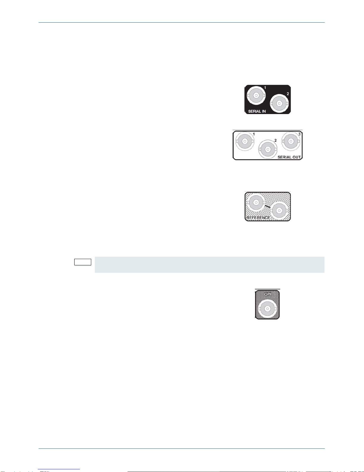
3.1.1 SDI Inputs
3.1.2 SDI Outputs
3.1.3 Analog Reference Input
It should be noted that proper operation to the full specification can only be achieved with a
correctly terminated, noise-free, stable, black sync reference input. Whilst lock may be
achieved with an unsuitable sync source the increased jitter evident on the SDI output will
affect locking and cable length performance at the receiving equipment.
3.1.4 GPI
Serial digital inputs to the unit are made to the
unit via two BNC connectors which terminate in
75 Ohms.
Serial digital outputs from the unit are made to
the unit via BNC connectors which terminate in
75 Ohms.
• 3 outputs (IQSYN2126-1A)
• 4 outputs (IQSYN2127-2A /
IQSYN2139-2A).
The external sync input to the unit is made via
the passive loop-through BNC connectors for
75 Ohms.
Note: If the loop-through facility is not used, the unused BNC socket must be fitted with a 75 Ohm
terminator.
General Purpose Interface via BNC 75 Ohms
connectors may be configured as inputs or
outputs.
• 1 GPI (IQSYN2126-1A)
• 2 GPI (IQSYN2127-2A /
IQSYN2139-2A).
IQSYN21 www.snellgroup.com Card Edge LEDs
Issue 2 Rev 2 Page 15 ©2014 Snell Limited
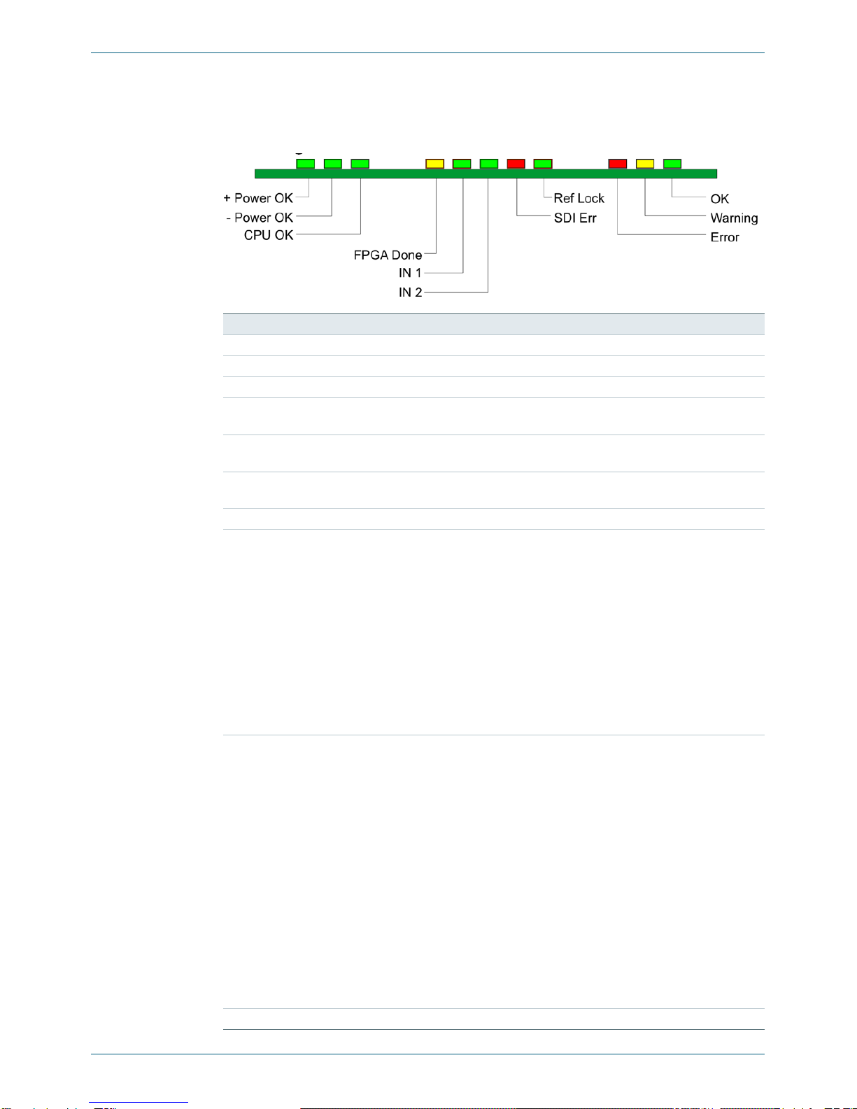
4. Card Edge LEDs
The LEDs on the edge of the module indicate its operating status:
LED Color Description
POWER + Green Indicates that a positive power supply is present.
POWER - Green Indicates that a negative power supply is present.
CPU OK Green Flashes to indicate that the CPU is running.
FPGA OK Yellow Flashes when the FPGA is running. When the unit is booting,
this LED is illuminated continuously, until the SDI is enabled.
IN 1, IN 2 Green These LEDs are illuminated when a valid input is present at the
Serial Data Inputs.
SDI ERR Red This LED is illuminated if any CRC, EDH or TRS errors are
detected on the selected SDI input or a loss of SDI.
REF LOCK Green This LED indicates that a reference signal is present.
ERROR Red This LED indicates board fault conditions.
When the unit is booting, this LED is illuminated, until the SDI is
enabled. Board fault errors include:
•Audio clock lock fault.Audio sub-system fails to lock to
video clocks.
•Serializer lock fault. Output serializer fails to lock.
•SDI JTAG board fault. Internal JTAG interface is
inadvertently enabled.
Continuous illumination indicates a board fault and a service is
required. Perform a Factory Reset and supply a valid SDI video
source before calling service.
WARNING Yellow This LED indicates operational errors.
Operational errors include:
•Embedder Status - ANC overflow. Indicates the
embedder has run out of ancillary space over quite a few
lines. Due to heavy use of ancillary space on the video
input, particularly in SD.
•Input Video: Incompatible input standard. Detected
input standard is invalid.
•Input Video: SDI problem. CRC or other SDI errors
detected on selected input in the last whole field.
•Reference: Lock Failure. Genlock failed to lock to
selected source.
This LED may be briefly illuminated in transitional states like
standard changes. Continuous illumination indicates a problem.
More information is available in the status window.
OK Green Indicates that the module is operating correctly.

IQSYN21 www.snellgroup.com Controlling the IQSYN21 from the RollCall Control Panel
Issue 2 Rev 2 Page 16 ©2014 Snell Limited
5. Controlling the IQSYN21 from the RollCall Control Panel
5.1 The Information Window
The information window is displayed in the upper-right corner of each screen and displays
basic information about the input status, video, audio and reference status of the module.
Select either Video Status or Audio Status to display the corresponding information.
5.1.1 Video Status
When Video Status is selected, the status of the video input and reference is displayed:
Name Status Description
INP:
(Line 1)
Displays the status of the video input, followed by the standard of the input, or
last valid signal.
OK 1080/29i Valid input signal received. Detected standard of input
signal, or last valid input signal, is displayed, e.g.
1080/29i.
LOST No input signal received.
FAIL Invalid input signal received, e.g. frame rate differs
between input and output.
MISM Valid input signal received but different (mismatched)
format to the selected output, e.g. input is 1080/29i and
output is 1080/29p.
OUT:
(Line 2)
Displays the operating standard of the unit.
Unknown The input signal standard is not recognized.
1080/29i Operating standard is displayed, e.g. 1080/29i.
REF:
(Line 3)
Displays the status of genlock, followed by the standard of the analog reference
signal when in Free-Run or Lock to Reference mode.
FREE Free run, with no reference connected.
OK F 1080/29i Free run. Detected standard of reference signal is
displayed, e.g. 1080/29i.
LOCK 1080/29i Valid reference and genlocked. Detected standard of
reference signal is displayed, e.g. 1080/29i.
LK F Valid reference but ambiguous field type.
LOST No reference signal found.
FAIL Genlock not possible.
FAIL INP Failed to genlock to input.
LOCK INP Genlocked to input video.
(Line 4) Displays the status of the ancillary data and the output picture.
ANC Ancillary present.
FRZ Output frozen.
PAT Output pattern.
MON Monochrome.
HBL Horizontal ancillary data is being blanked.
BLK Output black.

IQSYN21 www.snellgroup.com Controlling the IQSYN21 from the RollCall Control Panel
Issue 2 Rev 2 Page 17 ©2014 Snell Limited
5.1.2 Audio Status
When Audio Status is selected, the status of the embedded audio input is displayed where:
Name Status Description
Audio Input
Emb:
--------
P Channel is a PCM audio input.
No audio input is detected.
D Signal is data (non-PCM, Dolby, etc.).
CLIP Displayed if any audio level reaches the 0 dBFS point, i.e.
the digital limit. The fader level should be reduced to
prevent this occurring.
ANC FULL Indicates the embedder / ancillary formatter has run out
of ancillary space over quite a few lines and has lost data.
Caused by heavy use of ancillary space on the video
input, particularly in SD.
IQSYN21 www.snellgroup.com Controlling the IQSYN21 from the RollCall Control Panel
Issue 2 Rev 2 Page 18 ©2014 Snell Limited
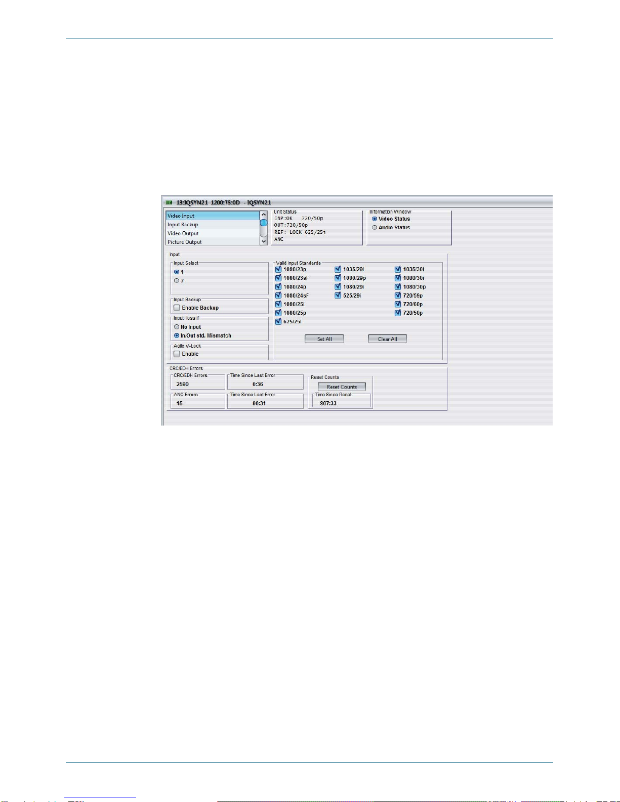
5.2 Video Input
The Video Input screen enables you to specify the settings for the video inputs:
• Selection of input source.
• Enable any specified backup rules.
• Specify the input loss conditions.
• Specify valid input standards.
• View information about CRC/EDH errors.
5.2.1 Input Select
Enables the selection of either input 1 or Input 2 for processing. This control is duplicated on
the Input Backup screen.
5.2.2 Input Backup
When selected, if a backup rule is triggered, the action defined in the backup rules takes place.
This control is duplicated on the Input Backup screen.
5.2.3 Input Loss If
The module can take automatic action if the input signal is lost. This control defines what is a
loss of input and what will cause the automatic actions to be triggered.
•No Input: If there is no input signal of any type this will be considered to be a loss of
input.
•In/Out std. Mismatch: If the standard of the input signal does not match the output
standard this will be considered to be a loss of input.

IQSYN21 www.snellgroup.com Controlling the IQSYN21 from the RollCall Control Panel
Issue 2 Rev 2 Page 19 ©2014 Snell Limited
5.2.4 Agile V-Lock
This function is intended to permit correct reception of upstream switched misaligned 625/25i
and 525/29i sources without picture disturbance. In HD standards, a mechanism is in place to
re-synchronize after a switch, which makes this mode unnecessary. A tolerance of +/- 5 lines
misalignment between sources is permissible which is wider than the 5 μs allowance specified
in SMPTE RP-168, and it is assumed that the correct switch point with respect to the source
is used.
5.2.5 Valid Input Standards
The Valid Input Standards check boxes specify the video input standards that the module will
accept. The module will automatically detect the standard of the received input and block any
signal that does not comply with these selected video formats.
By default, all input standards are selected.
•Set All: Click this button to select all check boxes.
•Clear All: Click this button to deselect all check boxes.
5.2.6 CRC/EDH Errors
This item provides information about the Cyclic Redundancy Checksum errors (CRC) and
Error Detection Handling (EDH).
•CRC/EDH Errors: This displays the total CRC or EDH Full Frame error count since
the last reset.
•Time Since Last (CRC/EDH) Error: This will show the time in 5 second intervals up
to 1 minute then in minute intervals, since the last error was detected.
•ANC Errors: This will display the total number of ancillary data (ANC) errors since the
last reset. All ancillary packets are checked. Hence, a problem video source or
dropout can produce a large number of errors.
•Time Since Last (ANC) Error: This will show the time in 5 second intervals up to 1
minute then in minute intervals, since the last ancillary data error was detected.
•Reset Counts: This will reset the error counters to zero.
•Time Since Reset: This will show the time in 5 second intervals up to 1 minute then in
minute intervals, since the counters were last reset.
Note: Due to the time required to recognize a change in picture framing in standard definition (SD)
there must be a minimum delay of 4 lines so that no displaced picture is seen at the output
during a misaligned switch. This may be assured in a synchronizing mode (external
reference or free-run) by setting the Frames delay value to at least 1.
Application areas that require agility over delay will suit this function better. Poor and
unstable signals may benefit from having this function disabled.
Note: Correct operation of agile V-lock requires a correct vertical reference point. On some legacy
equipment from before 1995 the end of vertical blanking was on the permissible lines 10-19
as well as on the current line 20. This practice is no longer permitted, and will prevent correct
vertical alignment of non-compliant legacy 525/59i sources. If this is the case then disable
Agile V-Lock.
Note: If any other standards are detected, an invalid standard will be assumed and this will force
an input video loss with the FAIL status.
Note: If the selected input changes, the CRC/EDH counts will be automatically reset once the
software has decided that the input is correctly locked.
IQSYN21 www.snellgroup.com Controlling the IQSYN21 from the RollCall Control Panel
Issue 2 Rev 2 Page 20 ©2014 Snell Limited
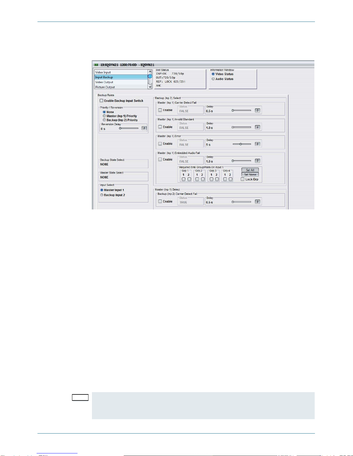
5.3 Input Backup
The Input Backup screen enables the IQSYN21 to be configured to detect if the input signal
on Master (Inp 1) fails and automatically switch to the Backup (Inp 2) signal.
5.3.1 Enable Backup Input Switch
Select this option to enable the input backup switch functions. This control is duplicated on the
Video Input screen.
5.3.2 Priority / Reversion
These settings apply to the Carrier Detect Fail controls and specify the input that will be given
priority and the time that a lost signal must have been regained before the system will revert
to the input that has priority.
•None: Neither Input 1 nor Input 2 has priority. If a signal is lost, causing the module to
switch to the other input, when the signal is regained, the module will not revert to the
original input.
•Master (Inp 1) Priority: Input 1 has priority. Normally, the module will use the Input 1
signal. If the signal on Input 1 is lost, the module will switch to Input 2. If the signal on
Input 1 is subsequently recovered, the module will revert to using Input 1 after the
time specified as the Reversion Delay has elapsed.
•Backup (Inp 2) Priority: Input 2 has priority. Normally, the module will use the Input 2
signal. If the signal on Input 2 is lost, the module will switch to Input 1. If the signal on
Input 2 is subsequently recovered, the module will revert to using Input 2 after the
time specified as the Reversion Delay has elapsed.
•Reversion Delay: Use the slider bar to specify the time that must elapse before the
priority input will revert to a recovered signal. The range of adjustment is 0 - 100
seconds and the preset value is 0 s.
Note: If the signal fails on both Input 1 and Input 2, the unit will switch to the priority input.
If any of the Backup (Inp 2) Select controls are enabled, the Priority/Reversion controls will
not be available.
Table of contents
Popular Recording Equipment manuals by other brands

Superscope
Superscope PSD450mkII quick start guide

Dantel
Dantel 49018 Installation & operation manual

Disaster Area Design
Disaster Area Design DMC-3XL Gen3 user manual

Leprecon
Leprecon LM-850 manual

Monroe Electronics
Monroe Electronics R194 instruction manual

Advanced Bionics
Advanced Bionics Naida CI M90 manual


