Snell E.5mk2 User manual

E.5mk2
K.5mk2
CR.5mk2
E.5mk2 Tower, K.5mk2 Monitor, CR.5mk2 Center Channel
Owner’s Manual

Specifications
Frequency Response (±3dB)
Recommended Amplifier Power
Nominal Impedance
Sensitivity [1 watt (2.83v) at 1m]
Tweeter (video-shielded)
Bass Unit (video-shielded)
Placement Switch Positions
Cabinet Construction
Platform Baffle Construction
Grille
Dimensions (HxWxD)
Weight/each
Finish
2
SPECIFICATIONS
E.5mk2 Tower
37-20,000Hz
20-250 watts
4 ohms
90dB
Front-firing: 1-inch (25mm)
black-anodized aluminum
dome with neodymium magnet
structure and multi-finned
aluminum heatsink
Rear-firing: 1-inch (25mm) soft
dome
Dual 61⁄2-inch (165mm) bass
units. Variably progressive spi-
der and aluminum shorting
cylinder permit high output
without increased distortion.
Copolymer cones and butyl
rubber surrounds resist envi-
ronmental extremes.
Normal and Boundary
3⁄4-inch MDF walls, I-beam
internal bracing
Exposed layer: 3⁄4-inch high-
density fiberboard
Damping layer: 1.5mm
neoprene
Inner layer: 3⁄4-inch medium-
density fiberboard
Custom-perforated (51% open)
cold-rolled steel, powder-coat
finish
423⁄8x 81⁄2x 111⁄2"
108 x 22 x 29cm
46 lbs (21kg)
Hand-sanded, hand-oiled
Cherry veneer, or hand-painted
Black on American Oak veneer
K.5mk2 Monitor
48-20,000Hz
50-250 watts
8 ohms
86dB
1-inch (25mm) black-anodized
aluminum dome with
neodymium magnet structure
and multi-finned aluminum
heatsink
61⁄2-inch (165mm) bass unit.
Variably progressive spider and
aluminum shorting cylinder
permit high output without
increased distortion. Copolymer
cone and butyl rubber surround
resist environmental extremes.
Normal and Boundary
3⁄4-inch MDF walls, I-beam
internal bracing
Exposed layer: 3⁄4-inch high-
density fiberboard
Damping layer: 1.5mm
neoprene
Inner layer: 3⁄4-inch medium-
density fiberboard
Custom-perforated (51% open)
cold-rolled steel, powder-coat
finish
18 x 81⁄2x 12"
46 x 22 x 30cm
26 lbs (11.4kg)
Hand-sanded, hand-oiled
Cherry veneer, or hand-painted
Black on American Oak veneer
CR.5mk2 Center Channel
70-20,000Hz
50-200 watts
8 ohms
89dB
1-inch (25mm) black-anodized
aluminum dome with
neodymium magnet structure
and multi-finned aluminum
heatsink
Dual 51⁄4-inch (135mm) cast-
aluminum baskets. Copolymer
cone and butyl rubber surround
resist environmental extremes.
Normal and Boundary
3⁄4-inch MDF walls, I-beam
internal bracing
Exposed layer: 3⁄4-inch high-
density fiberboard
Damping layer: 1.5mm
neoprene
Inner layer: 3⁄4-inch medium-
density fiberboard
Custom-perforated (51% open)
cold-rolled steel, powder-coat
finish
65⁄8x 17 x 99⁄16"
16 x 43 x 24cm
17 lbs (7.7kg)
Hand-sanded, hand-painted
Black on American Oak veneer

3
PRODUCT DESCRIPTIONS
E.5mk2 Tower
Floorstanding system
The E.5mk2’s slim cabinet design, Placement Switch, and video shielding pro-
vide unequaled positioning flexibility in your home. The driver complement in
this tower includes a 1-inch (25mm) black-anodized aluminum dome front-
firing tweeter, and 1-inch (25mm) soft-dome rear-firing tweeter for added
ambiance. A pair of 61⁄2-inch (165mm) bass units provides midrange and bass
to 37Hz (-3dB).
K.5k2 Monitor
High-performance monitor for use in a cabinet or on stands
The K.5mk2 Monitor is sized to fit in virtually any audio/video cabinet. Its
Placement Switch and smooth off-axis frequency response ensure a natural sonic
presentation when placed on stands, brackets, or in a cabinet. This two-way moni-
tor uses a 1-inch (25mm) black-anodized aluminum dome tweeter and a 61⁄2-inch
(165mm) bass unit. Both are video-shielded for placement near a TV.
CR.5mk2 Center Channel
Full-range music- and movie-quality center channel
The CR.5mk2 Center Channel is tuned to match the tonal balance of the E.5
Tower and K.5 Monitor for seamless 5 channel music or movie reproduction.
This 21⁄2-way design uses a 1-inch (25mm) black-anodized aluminum dome
tweeter and two 51⁄4-inch (135mm) bass units. One unit concentrates on the
midrange; the other supports deeper bass information to 70Hz — making the
CR.5 suitable for Dolby® Digital soundtracks. Video shielding, a Placement
Switch, and smooth off-axis frequency response allow placement above or
below a TV or in a cabinet.

4
SERIES FEATURES
1
3
9
5
6
2

5
Handmade Cabinets
Our cabinet department hand assembles each
unit, and then hand sands each several times.
The result is a cabinet of exceptional workman-
ship, with sharp corners and smooth sides.
Veneers
We use premium, book-matched veneers in our
oiled cabinets, chosen for grain consistency and
aesthetics. A pair of speakers uses wood veneer
from the same tree, so grain patterns are con-
sistent. Our cabinet shop sequences the veneer,
maintaining a match for the top, right/right,
and left/left sides of each pair of speakers. We
even go so far as to veneer the inside of the
cabinet. This way, as the cabinet experiences
changes in humidity in your home, it won’t
warp or come apart at the edges.
Placement Switch
This switch ”normalizes“ the speaker when it is
placed in a cabinet or next to a large object,
like a big-screen TV. This Snell feature assures
predictable performance of your speaker in
everyday settings.
Heat Sink/Terminal Plate
Available on the E.5mk2 Tower and
K.5mk2 Monitor
Heat-producing crossover components are
mounted to a die-cast aluminum heat sink for
stable, consistent performance at high power.
This large heat sink also draws heat from inside
the cabinet, keeping critical driver components
cooler. The terminal plate has two sets of five-
way gold-plated binding posts for bi-wiring or
bi-amplifying.
Rear-Firing Tweeter
The rear-firing tweeter on the E.5mk2 Tower
adds necessary high-end ”fill“ to the sound-
stage, creating a broader, deeper stereo image
when the speaker is placed away from a back
wall. An on/off switch allows you to defeat the
rear tweeter when the E.5mk2 is placed up
against a back wall.
Platform Baffle
This three-layer sandwich isolates the baffle
from the cabinet to decrease panel resonances
and distortion —especially in the critical
midrange. The Platform Baffle consists of mate-
rials of varying density —an extremely dense
outer layer to which the tweeter and bass units
are mounted, a ”squishy“ neoprene middle
layer, and a medium-density inner layer which
attaches to the cabinet.
Radiused-Edge Baffle
The elliptical radius on our baffle edge reduces
re-radiation for a cleaner and smoother
response —especially off-axis. Snell pioneered
this technique in the original Type A speaker
system in 1976.
Grille Design
The custom-perforated metal grille has no
frame to cause degrading reflections in the
upper frequencies. Rubber mounts isolate the
grille posts from the Platform Baffle.
Hand-Tuned Crossover
These networks adhere to an “in-phase” or
Linkwitz Reilly design. (Time alignment and
coherency are achieved through the transition
region from driver to driver.) Each crossover is
individually tuned by our technicians to within
±0.5dB of the Master Reference, assuring pre-
dictable performance in your home.
1
2
3
4
5
6
7
8
9
8
7
4

E.5mk2 Tower
The E.5mk2 Tower is designed for either freestand-
ing or boundary placement.
Freestanding placement refers to a situation in
which the E.5mk2 Tower has at least a 12-inch
(30cm) clearance on all four sides.
➤Away from large furniture
➤Not close to walls
Boundary placement refers to a situation in which
the E.5mk2 Tower is bounded on at least one side
by a large object:
➤Placed beside a TV
➤Placed beside a bookshelf or an audio/video
➤Placed next to a wall
Setting the Carpet Spikes
Four steel spikes (#5/16-18 thread) are included
with the E.5mk2. Use them when placing the
E.5mk2 on the carpet to balance the speaker.
6
HOW TO PLACE YOUR SPEAKER SYSTEMS
3
2
2
3
1
Freestanding Boundary
1Setting the Placement Switch (far left switch)
Freestanding placement:
Set the Placement Switch to NORMAL.
Boundary placement:
Set the Placement Switch to BOUNDARY.
Asymmetrical placement:
Based on your room layout
,
you might find that
one speaker performs best in the BOUNDARY
setting, and the other in the NORMAL setting.
Setting the Treble Level (mid-switch)
The Treble Level Control contours the ”bright-
ness“ of the E.5mk2 Tower.
➤Turn the Treble Control to +to increase the
high-frequency output in situations in
which the E.5mk2 sounds dull.
➤Turn the Treble Control to -when the
E.5mk2 is overly bright —especially in
highly reflective rooms.
Setting the Rear-Firing Tweeter (far right)
The rear-firing tweeter adds spaciousness and
ambiance to the soundstage, and is particularly
effective when the E.5mk2 is placed at least 12
inches (30cm) from a back wall.
Turn the rear-firing tweeter OFF when:
➤The E.5mk2 is placed directly against a back
wall.
➤The soundstage sounds too bright for your
taste.

7
K.5mk2 Monitor
The K.5mk2 Monitor is designed for either free-
standing or cabinet placement.
Freestanding placement refers to a situation in
which the K.5mk2 Monitor has at least a 12-inch
(30cm) clearance on three sides.
➤On stands - away from any furniture
➤On a wall bracket
➤On an open bookshelf
Cabinet placement refers to a situation in which
the K.5mk2 Monitor is bounded on at least one
side by a large object:
➤In an audio/video cabinet
➤On a crowded bookshelf
➤On stands, but placed right next to a TV
Setting the Placement Switch
Freestanding placement:
Set the Placement Switch to NORMAL.
Cabinet placement:
Set the Placement Switch to BOUNDARY.
Asymmetrical placement:
1. Based on your room layout, you might find that
one speaker performs best in the BOUNDARY
setting, and the other in the NORMAL setting.
2. You may place one K.5mk2 Monitor horizontally
and the other vertically without sound degrada-
tion.
Cabinet Placement
Freestanding Boundary
CR.5mk2 Center Channel
The CR.5mk2 is designed for either TV top or cabinet placement.
TV top placement refers to a situation in which the CR.5mk2 is:
➤On top of a 30-inch (76cm) or smaller TV, and the TV is freestanding in
your room.
Cabinet placement refers to a situation in which the CR.5mk2 is:
➤On top of a TV larger than 30 inches (76cm)
➤On top of a TV that is placed in an audio/video cabinet
➤Below a TV, on a shelf
Setting the Placement Switch
TV top placement:
Set the Placement Switch to NORMAL.
Cabinet placement:
Set the Placement Switch to BOUNDARY.
Placement Guidelines
The center channel keeps musical or soundtrack information centered in the
listening area. Therefore, its placement relative to the left and right speakers is
critical.
Place the speaker on top of or beneath your TV with its front edge as forward
as practical. Try to keep the front of the speaker flush with the front of the
screen.
Place the CR.5mk2 no higher or lower than 2 feet (60cm) of your left and
right speakers. If you need to place the speaker any higher or lower, angle it
toward ear level.
Attaching the Felt Bumpers
Four (4) felt bumpers are included with the CR.5mk2. Stick them to the bot-
tom of the speaker cabinet to protect the finish on your TV.
TV Top

8
Stand Placement
Stand height is not critical, but keep in mind that
shorter stands will place the bass units closer to a
boundary and will tend to increase bass response.
For best results:
➤Aim the center of the speaker to your ear level
while listening in a seated position.
Bass Levels
➤Moving speakers nearer to a wall increases bass
level.
➤Moving speakers toward a corner will increase
bass level even more.
➤Bass is often smoother (yet thinner) with speak-
ers placed well out from the wall, approximately
3 to 5 feet (1 to 1.5m).
➤Bass response is often smoother if you keep the
distance from the back wall and the distance
from the side wall distinctly different.
Experiment until you find the best overall sound
for your room. Choose a source with a heavy and
continuous bass line, repeat a short section until
you have a firm impression of it in your mind and
then try another speaker location. Repeat this
process until you are content with the bass
response you are getting. Moving your listening
position may affect the sound as much as moving
the speakers. Try different listener locations as well
as speaker locations.
Stereo Image
The distance between the speakers determines the
width of the stereo image. If the speakers are
placed too close together, the image will be too
narrow; too far apart and the blend will suffer,
creating a hole in the middle. When properly
placed, your speakers will create a continuum of
“Virtual Images” from left to right, with an illusion
of sound outside, in front, and behind the speaker
systems.
HOW TO PLACE YOUR SPEAKER SYSTEMS
General Guidelines
➤We recommend an angular separation between
45º and 60º (when viewed from above).
This is equivalent to a separation between the
speaker systems that is about 85% of the distance
to either of the speakers.
Creation of sounds between the speakers requires
some precise measurements. The distance from the
left speaker to the listener location should equal
the distance from the right speaker to the listener
location. We advise using a tape measure to equal-
ize these two distances to the primary listening
position. The payoff will be well worth the time
and effort.
Toe In
Toe in refers to the angling of the speaker systems
toward the listening location. Toe in is a matter of
taste. As the degree of toe in increases, the stereo
effect becomes more direct-sounding, like a pair of
headphones.
Toeing in should be the last step in the placement
of your speaker systems. After finalizing speaker
position and listening location, place the speaker’s
back parallel to the back wall or cabinet.
Experiment from there, turning the speaker by 10°
increments toward the listening area until you
achieve the desired effect.
Distance Between Speakers
Distance to Listening Area
45°to 60°

9
LISTENING LEVELS AND POWER HANDLING
The power recommendation for the system assumes you will operate the amplifier in a way that will not
produce distortion. All speakers can be damaged by a modest amplifier if it is producing distortion. If you
hear a gritty noise or other signs of strain, turn down the volume. Prolonged or repeated operation of
your speakers with a distorted signal can cause damage that is not covered by the warranty.
HOW TO CARE FOR YOUR SPEAKERS
For Black or White Painted Finishes
Including fronts, backs, bases, and metal grilles.
➤Use a soft terry cloth towel slightly dampened with water or a mild detergent. The towel should be just
damp enough to wipe the surface clean without leaving a trail of moisture.
➤Do not use abrasive cleaners or any cleaner containing chemicals harsher than those found in glass
cleaner.
For Oiled Natural Wood Finishes
To remove dust and fingerprints, use the same technique as above.
➤If your veneer begins to dry, apply a light coat of rose or lemon wood oil. This should return the wood
to its original richness.
➤Do not use spray waxes. These will create a buildup and eventually cause the veneer to appear dull
and lifeless.
Note: Your veneer’s appearance and color will mature and perhaps darken over time.
➤Avoid placing speakers in extreme conditions. If direct sunlight is unavoidable, be sure that there is
nothing partially covering the veneer in order to prevent ”tan lines“.
➤Avoid placing speakers where they could be subjected to standing water. It can cause the wood to
swell, breaking apart glue joints and ruining the air seal.
Grilles
You can remove the grilles from the speaker system and wipe with a damp cloth to remove any dust.

10
CONNECTING THE SPEAKERS
Choosing Cable
We recommend 16-gauge cable or thicker for runs up to 25 feet (8m) and 12-gauge wire or thicker for
longer runs. (We use a custom-configured 12-gauge oxygen-free cable in our crossover networks.)
Connecting with Bare Wire
Insert bare wire into holes and tighten.
Connecting with Banana Plugs, Spade Lugs, or Pins
The binding posts accept standard banana plugs and pins, and can accommodate spade lugs up to 5⁄16 inch.
Warning! To prevent electrical shock, always switch off the amplifier or receiver when making
connections to the speaker system.
Basic Connections
➤Keep the speaker terminal
jumper straps in place.
➤When making connections,
be sure to connect +to +
(red) and — to — (black).
Connecting the E.5mk2 and K.5mk2
K.5mk2 or E.5mk2
amplifier or receiver
speaker terminal
jumper straps
left speakerright speaker
low-frequency amplifier
high-frequency amplifier
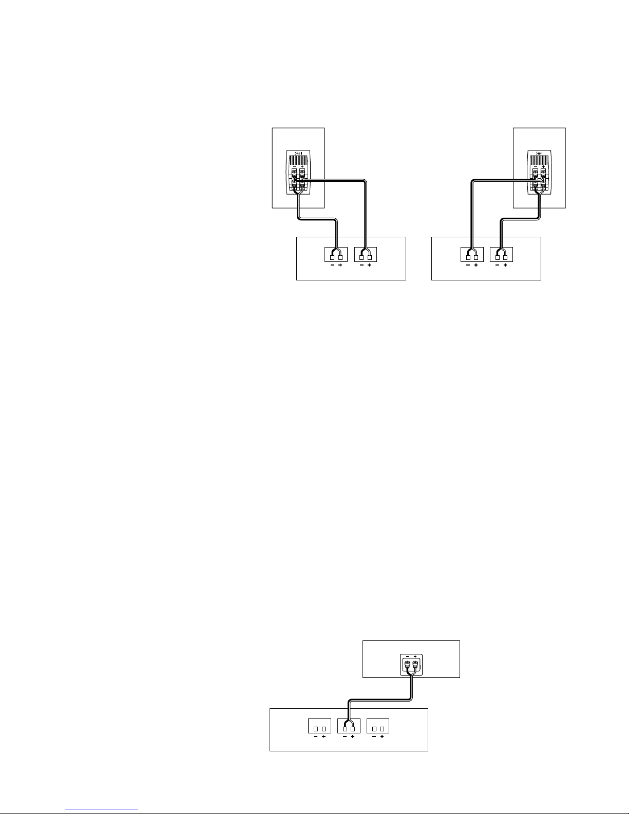
Bi-Amplifying
Using one amplifier for the bass, and one for the
high end:
1. Unscrew both sets of terminals and remove the
jumper straps.
2. Connect the cables from the bottom set of
terminals to the low-frequency amplifier driving
the bass units.
3. Connect the cables from the top set of terminals to
the high-frequency amplifier driving the tweeters.
4. Do not use an external crossover. It will interfere
with the phase and frequency response of the
E.5mk2 or K.5mk2.
K.5mk2 or E.5mk2
amplifier or receiver
Bi-Wiring
1. Use equal lengths of the
appropriate wire when
bi-wiring each speaker.
Consult your dealer for
cable options.
2. Unscrew both sets of
terminals and remove the
jumper straps.
11
Connecting to a Surround Processor
When using a powered subwoofer:
➤Select the SMALL or NORMAL setting on your
receiver or processor for your main and center
channels. This routes all bass information (typi-
cally below 120Hz) to your subwoofer.
When not using a powered subwoofer:
➤Select the LARGE setting on your receiver or
processor for your main speakers. This routes all
bass information (typically below 120Hz) to
your main speakers.
Match the sound levels of each speaker.
➤Your home theater system most likely includes
a test signal that simplifies level matching.
Refer to the instructions provided with these
electronics.
CR.5mk2
surround sound receiver or amplifier
left front center front right front
Connecting the CR.5mk2
Connecting the CR.5mk2 to a Surround
Processor
➤Select the SMALL or NORMAL setting on your
receiver or processor for the center channel. This
routes all bass information (typically below
120Hz) to your subwoofer.
➤When making connections, be sure to connect
+to +(red) and —to —(black).
➤Match the sound levels of each speaker. Your
home theater system most likely includes a test
signal that simplifies level matching. Refer to
the instructions provided with these electronics.
Using One Amplifier for Each Speaker
Make sure that the amplifiers are identical.
1. Unscrew both sets of terminals and remove the
jumper straps.
2. Connect the cables from the bottom set of
terminals to the first amplifier’s right channel.
3. Connect the cables from the top set of termi-
nals to the first amplifier’s left channel.
4. Repeat steps 2 and 3 for the second amplifier.
left speakerright speaker
right-channel amplifier left-channel amplifier

©2000 Snell Acoustics. All Rights Reserved.
Specifications are subject to change without notice.
Covered by patents issued and or pending.
Part #542-0002-1
LIMITED WARRANTY
For five years from the date of purchase, Snell Acoustics will repair for the original owner any defect in mate-
rials or workmanship that occurs in normal use of the speaker system, without charge for parts and labor.
Your responsibilities are to use the product according to the instructions supplied, to provide safe and
secure transportation to an authorized Snell Acoustics service representative, and to present proof of
purchase from an authorized Snell dealer in the form of your sales slip when requesting service.
Excluded from this warranty is damage that results from abuse, misuse, accidents, shipping, repairs, or
modifications by anyone other than an authorized Snell Acoustics service representative. This warranty
is void if the serial number has been removed or defaced.
This warranty gives you specific legal rights, and you may also have other rights that vary from state to state.
If Service Seems Necessary
Contact the dealer from whom you purchased the speaker system. If that is not possible, call us at
978-373-6114, or write to:
Snell Acoustics
143 Essex Street
Haverhill, MA 01832
We will promptly advise you of what action to take. If it is necessary to return your speaker system to
the factory, please ship it prepaid. After it has been repaired, we will return it freight-prepaid in the
U.S. or Canada.
143 Essex Street
Haverhill, MA 01832
978-373-6114 phone
978-373-6172 fax
This manual suits for next models
2
Table of contents
Other Snell Speakers System manuals


