Snell AMC 900 THX User manual

900
THX
2000
THX
AMC
Owner’s Manual
2
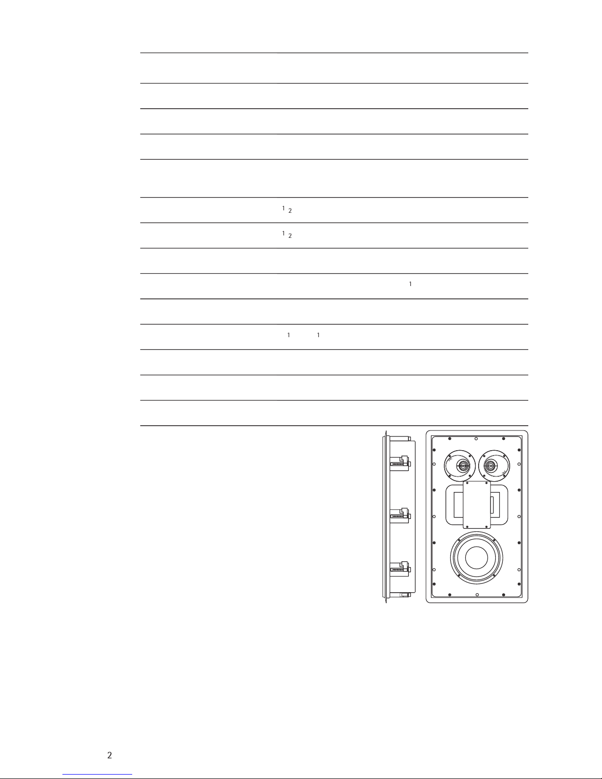
SPECIFICATIONS
Frequency Response (±3dB)
Recommended Amplifi er
Nominal Impedance
Sensitivity (2.83v at 1m)
Tweeter(s)
Midrange
Bass Driver
Crossover Point
Composite Baffl e
Grille
Dimensions (HxWxD)
Rough Opening Cutout (HxW)
Finish*
Shipping Weight
AMC 900
THX
78 Hz-20 kHz
10–150W
6 ohms
87dB SPL
(2) 1” aluminum dome, ferrofl uid cooling and heatsink.
“Directed Power” waveguide in dipole confi guration
3
1
/
2
” Midrange, edge-mounted in dipole confi guration
6
1
/
2
-inch (165mm) copolymer with butyl rubber surround
400 Hz, 2.5 kHz, 12dB/octave
Specialty adhesive between two
1
/
4
” layers of HD fi berboard
White cloth over MDF frame
23
1
/
4
x 13
1
/
4
x 3
3
/
4
inches (590 x 336 x 95mm)
22 x 12 inches (559 x 305mm)
White trim, suitable for painting
22 lbs (10kg) each
Manufactured under license from Lucasfi lm Ltd.
Lucasfi lm and THX are registered trademarks of
Lucasfi lm Ltd.

3
SPECIFICATIONS
Frequency Response (±3dB)
Recommended Amplifi er
Nominal Impedance
Sensitivity (2.83v at 1m)
Tweeter(s)
Midrange
Bass Driver
Crossover Point
Composite Baffl e
Grille
Dimensions (HxWxD)
Rough Opening Cutout (HxW)
Finish*
Shipping Weight
* Custom paint and grilles are available for an extra charge
AMC 2000
THX
63 Hz-20 kHz
75–250W
6 ohms
90dB SPL
1” aluminum dome with separate PVC surround and
ferrofl uid cooling
2 - 2
1
/
2
” in separate enclosure
2 - 8-inch (203mm) copolymer with butyl rubber surround
400 Hz, 2.5 kHz, 12dB/octave
Specialty adhesive between two
1
/
4
” layers of HD fi berboard
Perforated metal, 53% open
42 x 14 x 3
3
/
4
inches (1067 x 356 x 95mm)
40
7
/
8
x 12
7
/
8
inches (1039 x 327mm)
White trim, suitable for painting
45 lbs (20.4kg) each

4
INTRODUCTION: WHAT IS A HIGH END IN-WALL?
The Snell AMC series units bring a novel approach to the design and construction of in-wall
loudspeakers, expanding the boundaries of in-wall performance.
Our primary goal was to develop loudspeakers that delivered performance that was as close as
possible to that of our highly regarded freestanding loudspeakers, like the LCR7 and C7. To do
this, several issues had to be addressed.
The bass performance of conventional loudspeakers mounted in wall cavities is very unpredict-
able. Cavity volume can be large, which should be good for bass performance. However, with
one very short dimension (approximately 4”) and one very long dimension (up to 8’), the wall
cavity takes on the characteristics of a closed-end organ pipe. This creates a strong resonance
that tends to null out the bass. Lining this cavity with fi berglass will reduce the “Q” of the
notch but not restore the bass. What is needed is a defi ned volume of a more regular size. This
is best done with fully enclosed in-wall speakers.
The Snell AMC loudspeaker enclosure is a thin, but strong, aluminum tub. It is both damped
and braced. This largely contains the back radiated sound of the woofer within the enclosure.
An added benefi t of containing the woofer output is a reduced chance that resonances will be
excited in the house walls. Furthermore, sound “bleed through” to adjacent rooms is reduced.
To minimize resonances in the Snell enclosure, the speaker baffl e uses a technique fi rst
pioneered on our .5 and XA series loudspeakers. The baffl e is a three part composite with MDF
(fi berboard) outer layers around a thin, but highly effective, damping layer. This controls the
panel resonances of the baffl e that can obscure midrange clarity. As we have found with our
freestanding loudspeakers, a better loudspeaker cabinet means a better sounding loudspeaker.
Conventional in-wall speakers also suffer from poor stereo imaging. Freestanding speakers can
be angled inward to produce a better central image and make listening position much less
critical. Obviously, most in-wall speakers obviously cannot be angled in this way. Some in-wall
speakers use a pivoting post-mounted tweeter in attempt to overcome this limitation. The piv-
oting mechanism produces refl ections that adversely affect the tweeter’s response and sound.
Also, the small baffl e area of the pivoting tweeters means that only the highest frequencies
can be angled inward. The AMC 2000
THX
has an optional angled mounting plate for the high
frequency and midrange drivers.
The AMC 900
THX
uses a different solution – a unique tweeter that incorporates a waveguide
with a fi xed 20 degree angle. The DPT (“Directed Power Tweeter”) waveguide design controls
refl ections to ensure smooth response. The waveguide is also large enough to function ef-
fectively over the full range of the tweeter.
In addition to these unique solutions, all traditional Snell attributes are retained. Highly coher-
ent in-phase crossover networks ensure a seamless blend from driver to driver. Drivers are
designed for smooth, wide range response and low distortion. Long sessions of listening and
adjusting give each system that special, characteristic Snell sound. Finally, that Snell sound is
guaranteed in every production pair by Snell’s proprietary 0.5dB production tuning techniques.

5
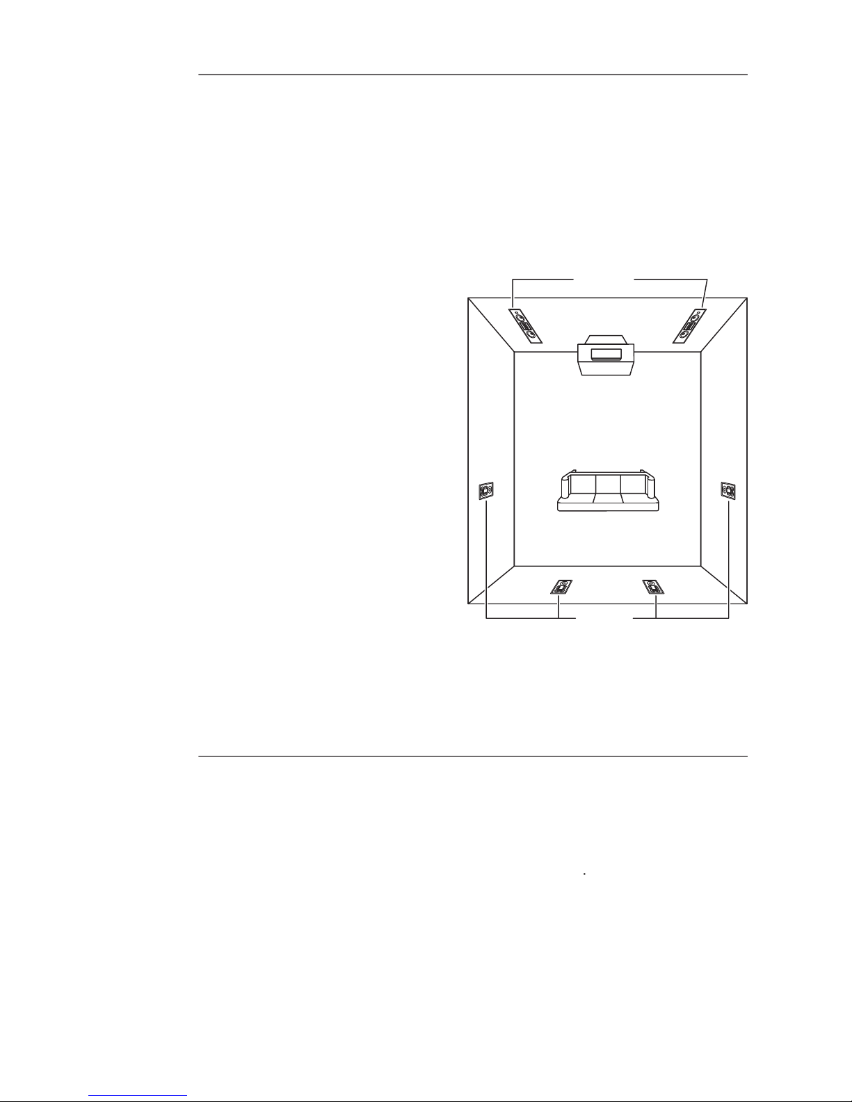
PLACEMENT OF THE AMC 2000
THX
A home theatre system includes three loudspeakers placed across the front of the listening
room. The distance between the left and right speakers determines the width of the stereo
image. If the speakers are placed too close together, the image will be too narrow; too far apart
and the blend will suffer, creating a hole in the middle. When properly placed, your speakers
will create a continuous “virtual image” from left to right, with an illusion of sound outside, in
front of, and behind the speaker systems.
We recommend an angular separation between 45 degrees and 60 degrees (when viewed from
above). This is equivalent to a separation between the speaker systems that is about 85% of the
distance to either of the speakers.
Creation of sounds between the speakers
requires some precise placement. The
distance from the left speaker, right
speaker, and center channel to the
listener location should all be as equal as
possible. We advise using a tape measure
to equalize these two distances to the
primary listening location.
Note:
If the AMC 2000
THX
’s must be
installed so the separation angle is larger
than 60°, consider using the optional
angled mounting plate for the tweeter
and midrange speakers. This produces a
“toe in” effect while still being mounted
fl ush with the wall. Contact your Snell
retail dealer or e-mail Snell Tech Support
at [email protected] for more
information.
Ideally the front channel speakers should
be installed at the same height as the ears of a seated listener. Try to keep the front channel
tweeters within two vertical feet of that height.
6
PLACEMENT OF THE AMC 900
THX
There are many opinions about where surround or “rear” speakers should be mounted. The
following is based on the fi ndings of the best academics, and on our experience with many
installations.
In a typical 5.1 surround system a dipole surround speaker, such as the AMC 900
THX
, performs
best when it is mounted directly to the sides of the listener plus or minus 15 degrees or so. This
places the listener in the “null plane” of the speaker. For a listener positioned on the null plane,
the output of the two tweeters and the midrange will be at maximum cancellation. The listener
will hear the speaker only via multiple wall refl ections—producing the most diffuse sound.
Whenever possible mount the AMC
900THX’s high on the side walls of the
room, at least one foot above the height of
a standing listener.
The second preferred position is on the
back wall. If may be necessary to mount
the speakers closer to the center line of the
room to keep the listening area in the ±15°
null plane.
If neither of these postions can be used,
mounting the speakers in the ceiling can
be considered. Ceiling mounted speakers
should be close to the side walls, well away
from an overhead position.
If a large theater room with three or more
rows of seats is planned, then more than
more than one pair of AMC 900
THX
may
be used to give more even coverage and a
more diffuse sound fi eld. We recommend
that a pair of surrounds be used for every
other seating row (the fi rst, the third, the fi fth, etc.). This follows standard cinema practice.
AN IMPORTANT NOTE ABOUT INSTALLATION
This manual assumes that the installer possesses skill in the proper use of hand and power tools,
knowledge of local building and fi re codes, and a familiarity with the environment behind the
wall or ceiling in which the speakers will be installed. If you do not have the necessary skills and
knowledge, have the speakers installed by a professional.
Optional preconstruction brackets are available for the AMC 900
THX
.

7
PAINTING THE SPEAKERS
If you intend to paint the speakers, it is best to do so before installation.
1) Remove the speaker grille.
2) Mask the baffl e.
3) After painting, carefully remove the paint mask.
Note:
Custom paint and grilles are available for an extra charge.
PREPARING FOR INSTALLATION
Map out the wiring paths from the speakers to the amplifi er. We recommend 16-gauge wire for
runs up to 25 feet, and 14-gauge wire for longer runs. Be sure the speaker wire does not rest or
rub against any sharp or pointed objects.
The speakers should be mounted on a fl at surface to form a good seal between the speaker
fl ange and the mounting surface.
When connecting more than two speakers per amplifi er channel, you should use series/parallel
wiring. In all cases, make certain that the total impedance does not fall below the amplifi er’s
rating. If you are not sure, contact your Snell Acoustics dealer.
You will Need:
1) A utility knife, an electric jigsaw, or other means of cutting a hole in the mounting surface.
2) A #2 Phillips screwdriver.
3) A wire cutter or stripper for preparing the speaker wires.
With the supplied hardware, the speaker can be installed in existing walls or ceilings from 1/2”
(12mm) to 11/2” (38mm). For thinner walls, you will need to use spacers for the mounting legs
(Contact your Snell dealer for this optional rubber part).
INSTALLATION
For convenient installation, the AMC 900
THX
and AMC 2000
THX
use a dog-leg mounting system.
(See illustrations below). This provides a quick and clean install. Furthermore, the dog-legs can
be removed if a particular situation requires to speaker to be directly attached to a stud.
1) Make an appropriate size speaker mounting cutout in the wall material.
2) Run the wire from the amplifi er to the cutout. Allow an extra foot of wire at the cutout.
Strip 1/2” (12mm) off the wire, and tightly twist the wire strands together.
3) Remove the speaker grille.
4) Insert the speaker wires into the spring terminal binding posts.
Important:
Typically, one side of the wire is
smooth. Connect this side to the – (black)
speaker terminal. The other side has a rib or
stripe. Connect this to the + (red) speaker
terminal. Connect wire at the amplifi er in
the same way. Failure to do so will result in
degraded sound.
Warning!
To prevent electrical shock, always
Warning! To prevent electrical shock, always Warning!
switch off the amplifi er or receiver when mak-
ing connections to the speaker system.
—continued

8
5) Place the speaker into the rough opening and level it.
6) Tighten (drive clockwise) the screws that turn the mounting clamp dog and tighten them.
Try to tighten each clamp the same amount, being careful not to over tighten them. See
diagram below for details.
Turn the mounting
clamps against the
enclosure, then
place the speaker
in the mounting
hole. Use a phillips
head screwdriver
to deploy the
mounting clamps
and pull them
against the back
of the drywall.
7) Replace the speaker grille.
Note: The AMC 900
THX
is sold in pairs. On the cabinet, near the input terminals, is a temporary
label to specify screen direction. The response will be slightly superior in this direction. Install
the two AMC 900
THX
’s so that the arrows BOTH point toward the screen. If listeners are not go-
ing to be located on or near the center axis of the speaker, the speaker should be oriented with
the arrow toward the listener location (even if this is away from the screen).
SETTING THE AMC 2000
THX
CONTROL SWITCHES
The AMC 2000THX has three switches that let you adjust its sound to suit your listening environ-
ment.
Bass Loading – When a speaker is placed close to a corner (or boundary), it can emphasize the
bass output. Setting the Bass Loading switch to the Boundary position slightly reduces bass
output, thus preventing the “heavy” sound quality that can result from a speaker being placed
close to a corner. When the AMC 2000THX is positioned at least 18” from the corner the Normal
switch postion will usually produce the best sound balance.
Treble Level – This switch controls the “brightness” of the AMC 2000THX. Set the switch to “+”
to increase the high-frequency output in situations where the speaker sounds “dull”. This can
occur when the listening room has a lot of heavy carpeting, drapes, etc. that absorbs high
frequency sound. Set the switch to “–“ when the AMC 2000THX sounds too bright, which can
happen in rooms with more hard, refl ective surfaces.
Perforated Screen – The AMC 2000THX provides compensation for the sound attenuation of a
speaker placed behind a perforated screen. When the speaker is behind a screen, set the switch
to With Screen. In systems where the speaker is not behind a screen, set the switch to No
Screen.
IMPORTANT: The With Screen setting of the Perforated Screen switch overrides the treble level
adjustment normally provided by the Treble Level switch. If you want to use the Treble Level
switch the Perforated Screen switch must be set to No Screen.

9
LISTENING LEVELS AND POWER HANDLING
The power recommendation for the system assumes you will operate the amplifi er in a way
that will not produce distortion. All speakers can be damaged by even a modest amplifi er if it is
producing distortion. If you hear a gritty noise or other signs of strain, turn down the volume.
Prolonged or repeated operation of your speakers with a distorted signal can cause damage
that is not covered by the warranty. It is especially important that you do not overdrive the
bass capability of smaller speakers. Watch for noises, such as pops, caused by the music’s bass
line. Use of the loudness control and/or full bass boost at louder volumes is likely to overdrive
the woofer. Use such controls sparingly.
HOW TO CARE FOR YOUR SPEAKERS
/
Use a soft terry cloth towel slightly dampened with water, glass cleaner, or a diluted mild
detergent. The towel should be just damp enough to wipe the surface clean without leaving
a trail of moisture.
/
Do not use abrasive cleaners or any cleaner containing chemicals harsher than those found
in glass cleaner.

10
LIMITED WARRANTY
For fi ve years from the date of purchase, Snell Acoustics will repair for the original owner any
defect in materials or workmanship that occurs in normal use of the speaker system, without
charge for parts and labor.
Your responsibilities are to use the product according to the instructions supplied, to provide
safe and secure transportation to an authorized Snell Acoustics service representative, and to
present proof of purchase from an authorized Snell dealer in the form of your sales slip when
requesting service.
Excluded from this warranty is damage that results from abuse, misuse, accidents, shipping,
repairs, or modifi cations by anyone other than an authorized Snell Acoustics service representa-
tive. This warranty is void if the serial number has been removed or defaced.
This warranty gives you specifi c legal rights, and you may also have other rights that vary from
state to state.
If Service Seems Necessary
Contact the dealer from whom you purchased the speaker system. If that is not possible, call us
at 978-538-6262, or write to: Snell Acoustics
300 Jubilee Drive, P.O. Box 3717
Peabody, MA 01961-3717
We will promptly advise you of what action to take. If it is necessary to return your speaker
system to the factory, please ship it prepaid in the original factory packaging. Please note that
Snell Acoustics will not be held liable for shipping damage due to improper packaging. After it
has been repaired, we will return it freight prepaid in the U.S. or Canada.


300 Jubilee Drive, P.O. Box 3717
Peabody, MA 01961-3717
phone: 978-538-6262
fax: 978-538-6266
email: [email protected]
www.snellacoustics.com
©2007 Snell Acoustics. All Rights Reserved.
Specifi cations are subject to change without notice.
Covered by patents issued and/or pending.
Part #542-1028
Other manuals for AMC 900 THX
1
This manual suits for next models
1
Table of contents
Other Snell Speakers System manuals


