Snell XA2900 User manual

XA 2900
Owner’s Manual
XA
2900


SPECIFICATIONS
Frequency Response (±3dB) 40-24,000Hz
Nominal Impedance 4 ohms
Minimum Impedance 3 ohms
Recommended Amplifier Power 150-600 watts
Sensitivity [2.83v at 1m] 88dB SPL
Driver Complement
Tweeter 1-inch (25mm) titanium dome with neodymium magnet and aluminum heat sink
Midranges Two 41/2-inch (110 mm) mounted in separate enclosure
Woofers Two 8 inch (210mm) with black anodized aluminum cones
Controls Four switches to fine-tune loudspeaker balance. Each switch has three
discrete settings to allow maximum flexibility for adjustment.
Cabinet Construction Heavily braced single wall cabinet sandwich baffle
Maximum Dimensions
Horizonal Configuration (HxWxD) 14x 32 x 131/2in (36 x 81 x 34cm)
Vertical Configuration (HxWxD) 32 x 14 x 131/2in (81 x 36x 34cm)
Net Weight 75 lbs (34kg) each
Shipping Weight 88 lbs (44kg) each
Finishes Black paint over MDF, custom finishes available at an additional charge.
Grille Cloth covered wood
1

2
Grille Design
Acoustically transparent grill cloth is applied over a
wood frame
Handmade Cabinets
The entire construction and finishing process is done by
hand. Each cabinet is assembled by our craftsmen, and
sanded several times before the black stain is applied. The
result is a cabinet of exceptional workmanship, with sharp
corners, smooth sides, and natural beauty.
Veneers
We use premium oak veneersfor the XA 2500 cabinets. We
even go so far as to veneer the inside of the cabinet to
ensure that it won’t warp or come apart at the edges when
exposed to changes in humidity.
Hand-Tuned Crossover
These networks adhere to an in-phase or Linkwitz-Reilly
design. (Time alignment and coherency are maintained
through the transition region from driver to driver.) Each
crossover is individually tuned by our production techni-
cians to within ±0.5dB of the master reference, ensuring a
consistent sound balance and predictable performance.
Toggle Switches
Toggle switches are the finest made in the US, and designed
to meet the stringent specifications of the aerospace
industry. These rugged switches are extremely reliable.
The switches are carefully tested and their circuits adjusted to
provide unprecedented options in adjusting spectral balance
as well as outstanding performance.
Multi-Element eXpanding Array
Snell first pioneered the XA technique with the XA90
system. Months of study and computer simulation resulted
in a scientifically designed five-element array with idealized
dispersion characteristics. We found that with a carefully
optimized crossover frequencies and slopes in conjunction
with precisely defined driver spacings, that a near constant
directivity and lobe free system was achievable. The net
result was a spectral balance with remarkably little
variation over the difficult vertical listening window and a
useful reduction in floor and ceiling bounce energy that
give the system a more revealing character.v You will note
that the central three drivers are mounted on a very
expensive solid machined MTM plate. This both allows their
spacing to be minimized and also lends the tweeter the
same vertical directivity as the rest of the array’s compo-
nents. Crossover and spacing of the outer bass units
continue the XA effect down to a very low frequency.
Inert Cabinet Construction
Previous models of Snell systems use a 3-part sandwich
baffle to deaden the mounting surfaces of the drivers. This
is a practical compromise with most of the benefit with
reasonable cost.
The XA 2900, however, has its entire enclosure built from a
multi-layer inert box technique. Cabinet walls are con-
structed from 2 wooden layers bonded together with a high
loss polymer adhesive. The end result is an inert cabinet
design that produces cleaner bass and purer midrange than
traditional cabinets built with heavy single wall construc-
tion.
XA 2900 FEATURES

1
2
4
5
6
6
3
3

PLACEMENT OF YOUR SPEAKER SYSTEM
Stereo Image
The distance between the speakers determines the width of
the stereo image. If the speakers are placed too close
together, the image will be too narrow; too far apart and
the blend will suffer, creating a hole in the middle. When
properly placed, your speakers will create a continuum of
virtual images from left to right, with an illusion of sound
outside, in front of, and behind the speaker systems. We
recommend an angular separation of approximately 50
degrees (when viewed from above). This is equivalent to a
separation between the speaker systems that is about 85%
of the distance to either of the speakers from the listener
location.
The distance from the listener location to the left speaker
and the right speaker should be as equal as possible. We
advise using a tape measure to ensure the distance from
each of the speakers to the primary listening position is the
same. The result will be well worth the time and effort.
50°
Distance Between Speakers
Distance to Listening Area
Room-Related Bass Effects
Your room dimensions will determine the frequencies of a
phenomenon call “standing waves”. Where the speakers are
placed relative to the strong points and weak points (anti-
nodes and nodes) of these standing waves significantly
affects the bass characteristics of the system. Experiment
until you find the speaker locations that produce the best
overall sound for your room. Choose a musical selection
with a heavy and continuous bass line. Repeat a short
section until you have a firm impression of it in your mind.
Then try another speaker location. Repeat this process until
you are content with the bass response. Your goal should be
even reproduction of each bass note without undue
prominence of any of them. Moving your listening position
may affect the sound as much as moving the speakers. If
practical, try different listening locations as well as speaker
locations.
See Optimizing the Sound section of this manual for more
information.
Toe-In
Toe-in refers to the angling of the speaker systems toward
the listener location. Toe-in is a matter of taste. As the
degree of toe-in increases, the stereo effect becomes more
sharply defined, that is, more like listening to headphones.
Toe-in also improves the stereo effect for listeners seated in
off-center positions. Having your speakers aligned with
their backs parallel to the wall gives a more diffuse sound
with a less defined central image. Toeing-in should be the
last step in the placement of your speaker system. After
finalizing speaker position and listener location, place the
speakers with their backs parallel to the back wall or
cabinet. Experiment from there, turning the speakers
toward the listening area in 10-degree increments, until you
achieve the desired effect.
Grille Removal and Installation
The grille is held in place with 8 fastener that snap into
cups on the front of the cabinet. To remove the grille grasp
the grille frame at the corners and pull it straight off the
front of the cabinet. To replace the grillle, align the grille
frame with the front of the cabinet and push to snap it into
place.
4
Choosing Cable
We recommend high-quality, minimum 16 gauge speaker
cable for runs up to 25 feet (8m) and 12-gauge wire or
thicker for longer runs. (We use a custom-configured 14-
gauge oxygen-free cable in our crossover networks.)
Connecting with Bare Wire
Twist the strand of the wire into a neat bundle. Insert the
bare wire into the holes in the terminals and tighten.
Connecting with Banana Plugs, Pins or Spade Lugs
The binding posts accept single banana plugs and pins, and
can accommodate 5/16" or larger spade lugs.
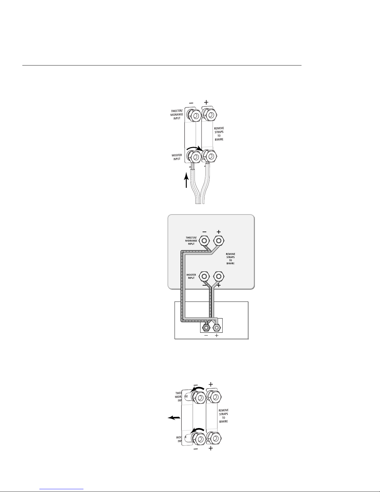
Basic Connections
Keep the speaker terminal jumper straps in place. When
making connections between the amplifier and speaker be
sure to connect + to + (red) and – to – (black).
CONNECTING THE SPEAKERS
Warning! To prevent
electrical shock, always
switch off the amplifier
or receiver when making
connections to the
speaker system.
am
p
lifie
r
XA 2500
5
Jumper Removal
Loosen both sets of terminals and slide the jumpers to the
side.
Bi-Amplifying
Using one amplifier for the bass and one for the high end
1. Unscrew both sets of terminals and remove the jumper
straps.
2. Connect the cables from the bottom set of terminals to
the low frequency amplifier driving the bass units.
3. Connect the cables from the top set of terminals to the
high frequency amplifier driving the tweeters.
Do not use an external crossover. It will interfere with the
phase and frequency response.
am
p
lifie
r
XA 2500
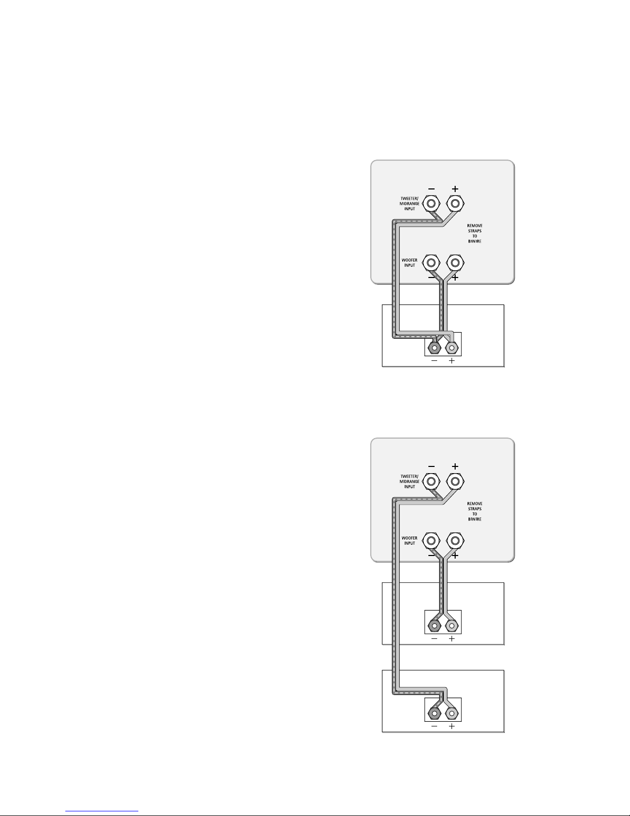
Bi-Wiring
1. Use equal lengths of the appropriate wire when bi-
wiring each speaker. Consult your dealer for cable
options.
2. Unscrew both sets of terminals and remove the jumper
straps.
am
p
lifie
r
XA 2900
amplifie
r
6
7
Using one amplifier for each speaker
Make sure that the amplifiers are identical.
1. Unscrew both sets of terminals and remove the jumper
straps.
2. Connect the cables from the bottom set of terminals to
the first amplifiers right channel.
3. Connect the cables from the top set of terminals to the
first amplifiers left channel.
4. Repeat steps 2 and 3 above for the second amplifier.
am
p
lifie
r
XA 2500
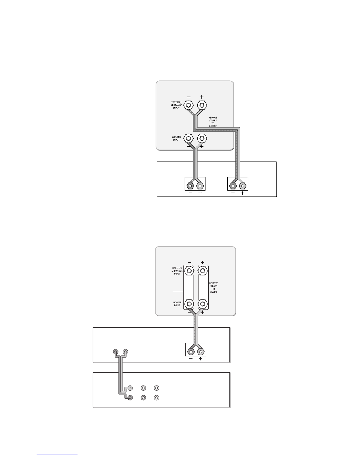
Using with a multichannel Surround Processor
1. Select the Large setting on your receiver or processor
for your main speakers. This routes all bass information
(typically below 100Hz) to your XA Towers.
2. Match the sound levels of each speaker. Your home
theater system most likely includes a test signal that
simplifies level matching. Refer to the instructions
provided with these electronics.
am
p
lifie
r
surround
p
rocesso
r
p
ream
p
out
p
ut
s
fr
o
n
t
su
rr
ou
n
d
sub
ce
n
ter
in
p
u
t
L
R
XA 2500
speaker
terminal
jumpers
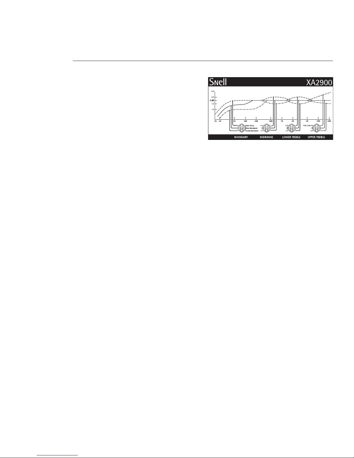
OPTIMIZING THE SOUND, SYSTEM ADJUSTMENTS
Probably the most unique feature of the XA 2500 is its total
adjustability via a number of band trim switches. At Snell,
our experience with installing and optimizing our systems
into a variety of homes has taught us the value of fine
adjustments to a speaker’s balance to suit both the
acoustics of the room and the characteristics of allied
equipment.
To do this we have split the sonic spectrum up into 4
sections. Each section has an electrical switch with 3 subtly
different setting. In the following section we will describe
what to listen for in each band and how to adjust them for
optimum performance.
First please note that all adjustments are subtle with
approximately 1.5dB difference per position. No combina-
tion of settings of the rear panel switches can make the XA
2900 sound bad. Also note that it is acceptable to leave
them all in their middle position as this will give the flattest
balance in a very good room with very neutral electronics.
We just feel that, with a little patience and experimenta-
tion, that an even better performance is achievable in most
case with judicious adjustment of the various controls.
The Boundry Switch allows you to adjust the bass
response of the low frequency range below 400 Hz to
compensate for the effect room placement has on bass
response. When the XA2500 is located at least 12 inched
(30cm) away from the surrounding walls use the upper
“Free Space” switch position. If the XA 2500 is placed
against a wall but at least 12 inches off the floor use the
middle “Rear Boundry” switch postion. When the XA 2500
is placed on the floor and against a wall use the lower
“Floor Placment” switch postion.
These recommendations are only a starting point. Listening
test should be used to determine if the initial switch setting
is the best choice. Listen to music that has a wide range of
sounds along with a strong bass component. If bass range
sounds or male voices sound “thick” or “tubby” try using a
lower Boundry switch setting. Do not set the Boundry switch
to a higher than necessary position in an attempt to achieve
“impressive” sounding bass. This will produce an unnatural
balance that will mask higher parts of teh sound range.
8
The Midrange Switch affects the upper harmonics of
human voice, especially vowel sounds like “i” and “eh”.
Again, listen and choose which of the 3 positions seems
most neutral.
Next switch up the spectrum would be for lower treble.
Excesses here give hardness to the character, whereas
absences lend “sweetness”. Some electronics and source
components can add harness to the chain and could be
compensated with the lower position. The upper position
might be used if the room’s acoustics are particularly dull.
The topmost spectrum adjustment is for the upper treble.
This range gives sparkle to the sound and contains the
highest harmonics of instruments, especially percussion
instrument as well as the bite of some brass instruments.
All of the adjustments can be usefully employed to
compensate for room acoustic issues. Also your listening
distance might have some bearing. Close listening distances
might warrant some reductions of the top two controls to
prevent the system from sounding overbearing. At greater
listening distances the same controls can offset the distant
perspective that naturally occurs.

9
POWER-HANDLING
The power recommendation for the system assumes you will
operate the amplifier in a way that will not produce
distortion. All speakers can be damaged by a modest
amplifier if it is producing distortion. If you hear a gritty
noise or other signs of strain, immediately turn down the
volume. Prolonged or repeated operation of your speakers
with a distorted signal can cause damage that is not
covered by the warranty.
CARING FOR YOUR SPEAKERS
For Painted Finishes (Including baffles, backs, and bases.)
Use a soft terry cloth towel slightly dampened with water,
glass cleaner or a diluted mild detergent. The towel should
be just damp enough to wipe the surface clean without
leaving a trail of moisture. Be very careful to not apply
pressure to the fronts of the drive units. Do not use abrasive
cleaners or any cleaner containing chemicals harsher than
those found in glass cleaner.
For Oiled Natural Wood Finishes
To remove dust and fingerprints, use the same technique as
above. If your veneer begins to dry, apply a light coat of
rose or lemon wood oil. This should return the wood to its
original richness. Do not use spray waxes. These will create
a buildup and eventually cause the veneer to appear dull.
Note: Your veneers appearance and color will naturally
mature and perhaps darken over time. Avoid placing
speakers in extreme conditions. If direct sunlight is
unavoidable, be sure that there is nothing partially covering
the veneer in order to prevent “tan lines”. Avoid placing
speakers where they could be subjected to standing water.
It will cause the wood to swell, breaking apart glue joints
and ruining the air seal. Grilles You can remove the grilles
from the speaker system and wipe them with a damp cloth
to remove any dust.
LIMITED WARRANTY
For five years from the date of purchase, Snell Acoustics
will repair for the original owner any defect in materials or
workmanship that occurs in normal use of the speaker
system, without charge for parts and labor. Your responsi-
bilities are to use the product according to the instructions
supplied, to provide safe and secure transportation to an
authorized Snell Acoustics service representative, and to
present proof of purchase from an authorized Snell dealer
in the form of your sales slip when requesting service.
Excluded from this warranty is damage that results from
abuse, misuse, accidents, shipping, repairs, or modifications
by anyone other than an authorized Snell Acoustics service
representative. This warranty is void if the serial number has
been removed or defaced. This warranty gives you specific
legal rights, and you may also have other rights that vary
from state to state.
If Service Seems Necessary
Contact the dealer from whom you purchased the speaker
system. If that is not possible, call us at 978- 538-6262, or
write to:
Snell Acoustics
300 Jubilee Drive, PO Box 3717
Peabody, MA 01961
We will promptly advise you of what action to take. If it is
necessary to return your speaker system to the factory,
please ship it prepaid in the original factory packaging.
Please note that Snell Acoustics will not be held liable for
shipping damage due to improper packaging. After it has
been repaired, we will return it freight-prepaid in the U.S.
or Canada.

300 Jubilee Drive, PO Box 3717
Peabody, MA 01961
phone: 978-538-6262
fax: 978-538-6266
email: info@snellacoustics.com
www.snellacoustics.com
©2004Snell Acoustics.
All Rights Reserved.
Specifications are subject
to change without notice.
Covered by patents issued
and or pending.
Part #542
Other manuals for XA2900
1
Table of contents
Other Snell Speakers System manuals


