Snibe Maglumi 2000 User manual
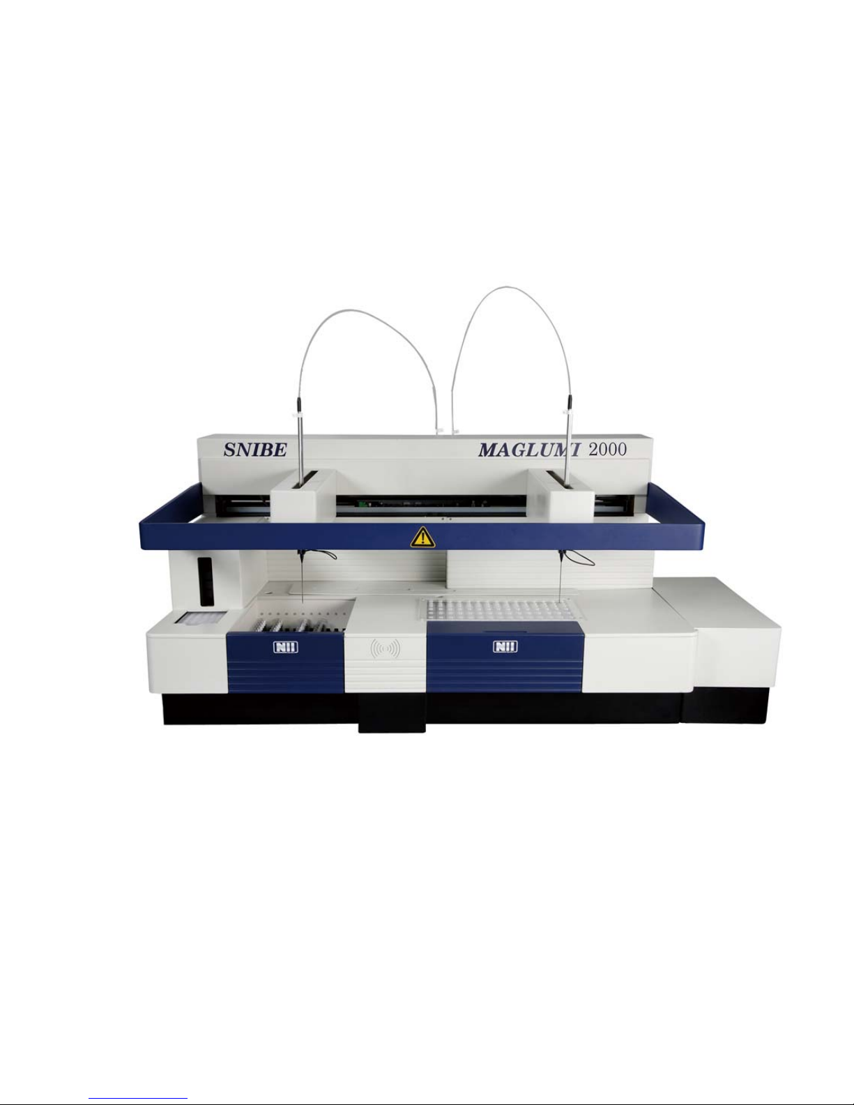
MAGLUMI®
Chemiluminescence Analyzer
Operating Instructions
Shenzhen New Industries Biomedical Engineering Co., Ltd


Safety Notes
Safety
Notes
1 CAUTION ON ELECTROMAGNETIC WAVE INTERFERENCE ----------------------------------------------2
1.1 ELECTROMAGNETIC WAVE INTERFERENCE GIVEN BY MAGLUMI®TO OTHER EQUIPMENT---------------2
1.2 ELECTROMAGNETIC WAVE INTERFERENCE THAT MAY BE GIVEN TO THE MAGLUMI®ANALYZER-------2
2 INSTALLATION, MOVEMENT, AND SERVICE-------------------------------------------------------------------3
3 OTHER CAUTIONS-------------------------------------------------------------------------------------------------------3
3.1 HANDLING CHEMICAL AND SAMPLES-------------------------------------------------------------------------------3
3.2 USE OF OPERATING INSTRUCTIONS --------------------------------------------------------------------------------3
4 PRINCIPLES FOR SAFE USE-----------------------------------------------------------------------------------------3
4.1 INTENDED USE /INTENDED PURPOSE-------------------------------------------------------------------------------3
4.2 COMMON CAUTIONS FOR SAFETY ----------------------------------------------------------------------------------4
5 DANGER OF FIRE--------------------------------------------------------------------------------------------------------5
5.1 HANDLING WITH FLAMMABLE CHEMICALS-------------------------------------------------------------------------5
6 DANGER OF EXPLOSION OF FLAMMABLE VAPOR----------------------------------------------------------5
6.1 HANDLING WITH FLAMMABLE CHEMICALS-------------------------------------------------------------------------5
7 DANGER OF ELECTRIC SHOCK ------------------------------------------------------------------------------------5
7.1 ELECTRIC SHOCK CAUSED BY TOUCHING THE ANALYZER INSIDE ---------------------------------------------5
7.2 ELECTRIC SHOCK CAUSED BY IMPROPER GROUNDING----------------------------------------------------------6
8 DETERIORATION OF USERS STATE OF HEALTH ------------------------------------------------------------6
8.1 INJURY TO HAND CAUSED BY NEEDLE OR MECHANISM ---------------------------------------------------------6
8.2 LASER BURNS CAUSED BY BARCODE READER-------------------------------------------------------------------7
8.3 CHEMICAL BURNS CAUSED BY REAGENTS ------------------------------------------------------------------------7
8.4 INFECTIONS CAUSED BY PATIENT SAMPLES-----------------------------------------------------------------------8
9 AFFECTED PROCESSING OF MAGLUMI®DIAGNOSTIC SYSTEM---------------------------------------9
9.1 COMMON CAUTIONS FOR SAMPLE STATION -------------------------------------------------------------------- 10
9.2 COMMON CAUTIONS FOR REAGENT STATION ------------------------------------------------------------------- 10
9.3 COMMON CAUTIONS FOR STARTER REAGENTS ---------------------------------------------------------------- 10
9.4 COMMON CAUTIONS FOR WASTE BAG--------------------------------------------------------------------------- 11
9.5 COMMON CAUTIONS FOR WASH SYSTEM------------------------------------------------------------------------ 11
9.6 COMMON CAUTIONS FOR COMPUTER SYSTEM AND SOFTWARE --------------------------------------------- 12
10 WORKING CONDITIONS OF MAGLUMI®ANALYZER ----------------------------------------------------- 12
11 WARNING LABELS ON MAGLUMI®ANALYZER------------------------------------------------------------ 12
Operating instructions Page 1

Safety Notes
1 Caution on Electromagnetic Wave Interference
1.1 Electromagnetic Wave Interference given by MAGLUMI®to other Equipment
The use of the MAGLUMI
®
Analyzer may interfere with radio
and television reception.
Use the cables attached at the installation for connection between
the devices in the system. The proper use of the specified cables
minimizes Electromagnetic Wave Interference.
Installation and service of the system or changes in the
installation may never be performed by persons not authorized by
SNIBE, especially never connect devices in the system with
movable multiple plug sockets.
However, there is no guarantee that the MAGLUMI
®
Analyzer will
not cause Electromagnetic Wave Interference.
a. When the MAGLUMI
®
Analyzer may be the cause, turn off the
power of this Instrument and check radio and television reception.
b. If it is improved, the MAGLUMI®Analyzer probably is the cause.
1.2 Electromagnetic Wave Interference that may be given to the MAGLUMI®Analyzer
If the MAGLUMI
®
Analyzer is used near equipment that generates
strong electric and magnetic field, noises may enter the Instrument
to affect the performances and functions.
Use the cables attached at the installation for connection between
the devices in the system. The proper use of the specified cables
minimizes electromagnetic wave interference.
Installation and service of the system or changes in the
installation may never be performed by persons not authorized by
SNIBE, especially never connect devices in the system with
movable multiple plug sockets.
However, there is no guarantee that the MAGLUMI
®
Analyzer will
not be affected by Electromagnetic Wave Interference.
When some equipment may be the cause, turn off the power of
the equipment and check the functions of the MAGLUMI
®
Analyzer.If they are improved, Interference from the equipment is
probably the cause.
Try the following to correct.
a. Move the MAGLUMI
®
Analyzer further away from the
equipment that may be the cause.
b. Connect the power cord of the MAGLUMI
®
Analyzer to an
outlet that is on a different circuit from the equipment that
may be the cause.
c. Check that the other equipment, which is connected with this
Analyzer, is not affected by Electromagnetic Wave Interference.
Page 2 Operating instructions

Safety Notes
2 Installation, Movement, and Service
Installation and service may only be performed by Service
Engineers of SNIBE or Technicians authorized by SNIBE, or
performed under the supervision of them.
For the installation, Customers or Users should make preparation
that satisfies the installation and working conditions referring to the
Instruction Manual.
When moving the MAGLUMI
®
Analyzer after the delivery, contact
SNIBE to avoid trouble related to the movement.
Make sure to use only equipment such as printers or screens,
which have been released by SNIBE. A complete system check-up
has to be performed after changes in the MAGLUMI
®
Diagnostic
System.
3 Other Cautions
3.1 Handling Chemical and Samples
When performing analysis by using the MAGLUMI
®
Diagnostic
System, Customers or Users should handle, keep, or process the
chemicals and samples following the specified regulations etc. on
their own responsibility following the suitable national regulations.
Follow the indications of each legal Manufacturer about handling,
keeping, and disposal of reagent, standard solution, and sample
for precision control.
3.2 Change of Operating Instructions
The contents of this Operating Instructions are subject to
change without previous notice. Please get information on the
actuality by Your Sales Representative.
4 Principles for safe Use
Before starting use of the MAGLUMI
®
Diagnostic System, read
carefully the following Explanation for safety, and understand
the contents completely.
4.1 Intended use / Intended Purpose
The MAGLUMI
®
Diagnostic System measures chemiluminescence. It
is intended strictly for professional In-vitro-Diagnostic use. It is to be
used only with Chemiluminescence Immunoassays, authorized by
SNIBE for the MAGLUMI
®
analyzer.
Operating instructions Page 3
Safety Notes
Page 4 Operating instructions
4.2 Common Cautions for Safety
The MAGLUMI
®
Diagnostic System is to be used only by
Professional Users.
Operate the Instrument following the indications and procedures
described in Operating Instructions for the MAGLUMI
®
Analyzer.
Follow all warnings, cautions, and notes indicated on the
MAGLUMI
®
Analyzer and in the operating Instructions. If not,
human injuries or damage to Instrument can be caused.
Caution on Safety is displayed by "Caution" or alert symbol as
follows.
The barcode reader is a laser beam. Never look directly into
thebarcode reader, as this can damage the eyes!
Before using the Reagent Integrals, read the IFU
(instructionsfor use) provided in the reagent package
(storage, preparation)!
NOTE The barcode reader is a laser beam. Never look directly into
thebarcode reader, as this can damage the eyes!
CAUTION The barcode reader is a laser beam. Never look directly into
thebarcode reader, as this can damage the eyes!
When using reagents or chemicals, ventilate the room well on your
own responsibility. If not, trouble on health can be caused.
For keeping safety, do not modify the MAGLUMI
®
Diagnostic
System, do not change the components or accessories, do not use
parts either than the specified, and do not remove the safety device.
Installation at the delivery is performed by Service Engineers of
SNIBE or Technicians certified by SNIBE, or performed under the
supervision of them to offer a safe and precise Analyzer.
Do not perform operation and function not described in the Operating
Instructions. If trouble occurs on the Diagnostic System, contact
SNIBE, or Sales Agent.
Cautions indicated on the MAGLUMI
®
Diagnostic System, in
Operating Instructions are prepared after careful examination,
however, phenomenon beyond prediction can occur. When
performing operation and maintenance, not only follow the
instructions, but also pay attention always by yourself.

Safety Notes
5 Danger of Fire
5.1 Handling with Flammable Chemicals
When using flammable chemicals such as organic solvents, there is
the possibility of catching fire.
For keeping safety, only use wash buffers, starter reagents
and diagnostic kits approved by SNIBE to assure not using
flammable chemicals in the working process.
This instrument is not explosion-proof type. Do not use organic
solvent in the direct surrounding of the analyzer whose ignition point
is lower than 65°C.
6 Danger of Explosion of Flammable Vapor
6.1 Handling with Flammable Chemicals
When flammable chemicals such as organic solvents are used in the
laboratory, there is the possibility of rising vapor concentrations
exceeding the explosion limit concentration, explosion can be
caused.
When using chemicals in the laboratory such as organic solvent,
which are flammable and easy vaporized, take care of leakages and
puddles, and ventilate the room sufficiently.
For keeping safety, only use wash buffers, starter reagents
and diagnostic kits approved by SNIBE to assure not using
flammable chemicals in the working process.
This instrument is not explosion-proof type. Do not use organic
solvent in the direct surrounding of the analyzer whose ignition point
is lower than 65°C.
7 Danger of Electric Shock
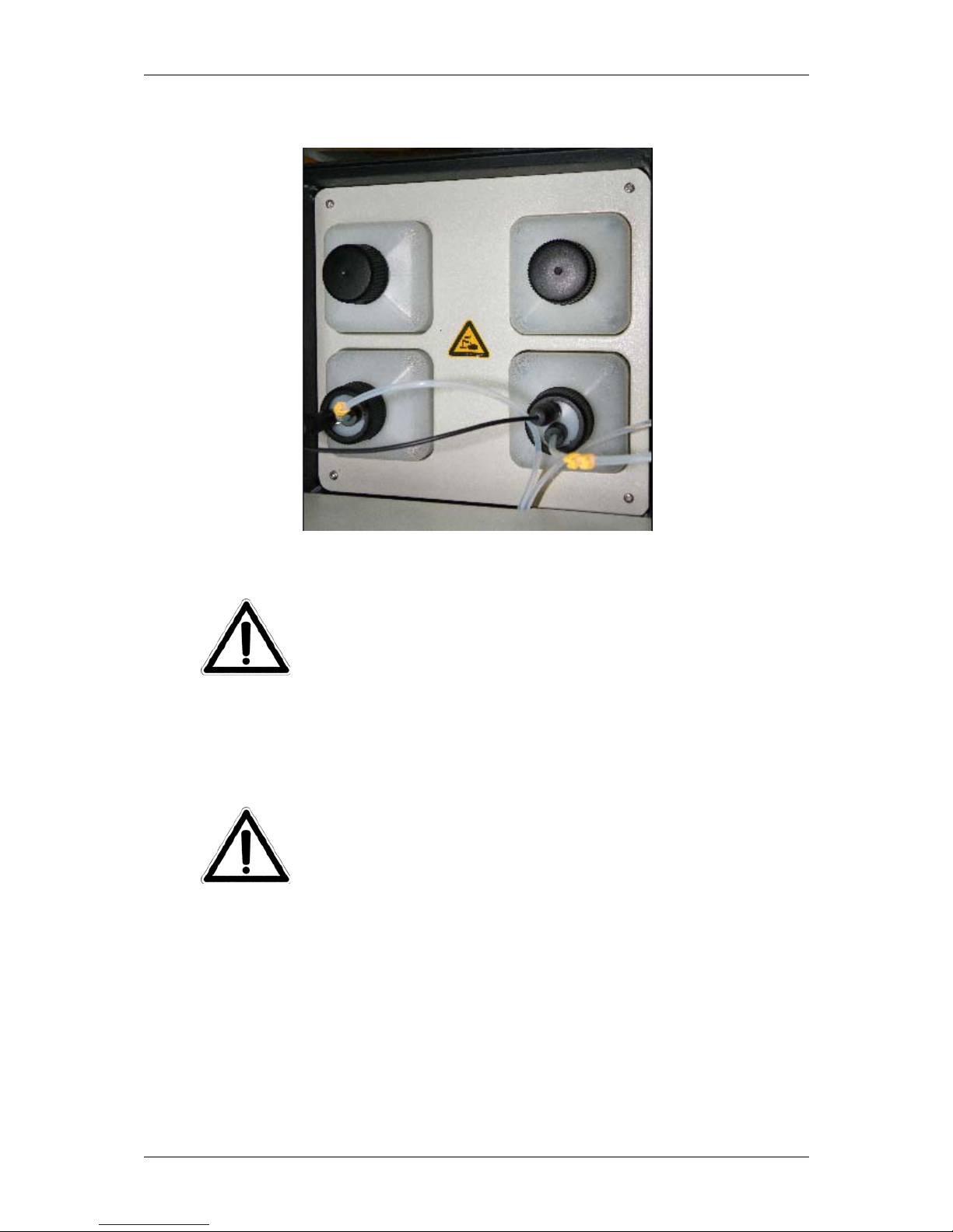
7.1 Electric Shock caused by touching the Analyzer Inside
When removing Cover of the MAGLUMI
®
Analyzer to work for
replacing parts, cleaning etc., turn off the power, disconnect the
Power Cord without fail.
Fig. 7.1-1: Safety Label nearby Power Connection
Operating instructions Page 5

Safety Notes
7.2 Electric Shock caused by Improper Grounding
Use Power Cable furnished with the MAGLUMI
®
Analyzer. Use of
Power Cable other than the specified one can cause Electric Shock.
8 Deterioration of users state of health
8.1 Injury to Hand caused by Needle or Mechanism
While running the Analyzer, do not insert your hand or anything into
the Apparatus, your hand, finger or arm can be injured
Capped sample tubes can cause a crash of the needle , therefore
make sure to uncap all sample tubes before the sample racks are
introduced into the MAGLUMI
®
Analyzer. If a needle crash occurs,
the
procedure defined in the Chapter “Sample Station” is to be followed.
The MAGLUMI
®
Analyzer may never been run without the mounted
Safety Shield in front of the pipetting area.
Cleaning and disinfecting actions can cause injuries by the needles,
therefore cleaning and disinfecting work is to be done only if the
MAGLUMI
®
Analyzer is not into service.
The Cleaning and Disinfection Procedure in this Operating
Instructions are strictly to be followed.
Fig. 8.1-1: Warning on Bar over Pipetting Area
Page 6 Operating instructions

Safety Notes
8.2 Laser Burns caused by Barcode Reader
The Laser Beam of the Barcode Reader can deteriorate vision of the
human eye, if the beam is focused on the retina.
While loading the Reagent Modules or the Patient Sample Racks into
the MAGLUMI
®
Analyzer, make sure to never look into the Laser
Beam of the Barcode Reader.
Fig. 8.2-1 Laser Beam Warning at the Sample Loading Area
8.3 Chemical Burns caused by Reagents
The chemical substances included in the Starter Reagents can cause
chemical burns when coming in direct contact to the skin.
Before the Starter Reagents are handled or loaded into the Analyzer
the package information for the starter reagents (MAGLUMI
®
Starter
Kit) is to be read thoroughly and followed by the user.
For keeping safety, only use wash buffer and starter reagents
approved by SNIBE. Loading the Starter Reagents it is
essential to ensure correct connection to starter 1 and starter
2.
Different Starter Systems can cause chemical reactions leading to
chemical burns and other deteriorations of health. Loading new
Starter Reagents may never be pooled.
Operating instructions Page 7
Safety Notes
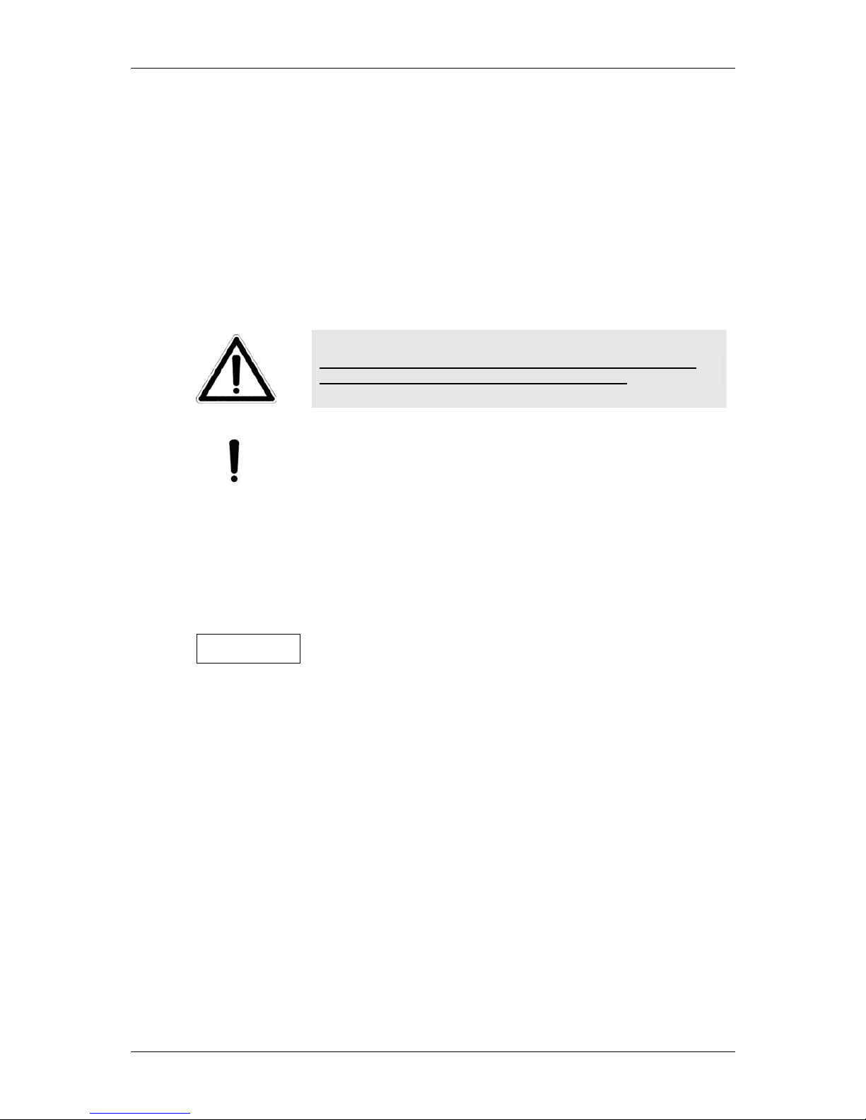
Fig. 8.3-1: No-Pooling Warning Labels on Starter Reagent housing
8.4 Infections caused by Patient Samples
The patient samples included in the Sample Tubes can be potential
infectious and therefore can deteriorate health of the users.
The reaction modules come into contact with the potentially
infectious material of the patient samples, therefore the reaction
modules are to be disposed of in the installed MAGLUMI
®
Waste
Bag to avoid contact with the modules and the potentially infectious
material.
The waste liquids are containing potentially infectious material of
the patient samples; therefore these liquids are to be disposed
according to the domestic requirements.
Cleaning and disinfecting actions can cause injuries by the needles,
therefore cleaning and disinfecting work is to be done only if the
MAGLUMI
®
Analyzer is not into service.
The Cleaning and Disinfection Procedure in this Operating
Instructions are strictly to be followed.
For keeping safety, the laboratory has to follow the national rules and
standards for biological laboratory safety and quality control
measures in diagnostic laboratories.
Page 8 Operating instructions
Safety Notes
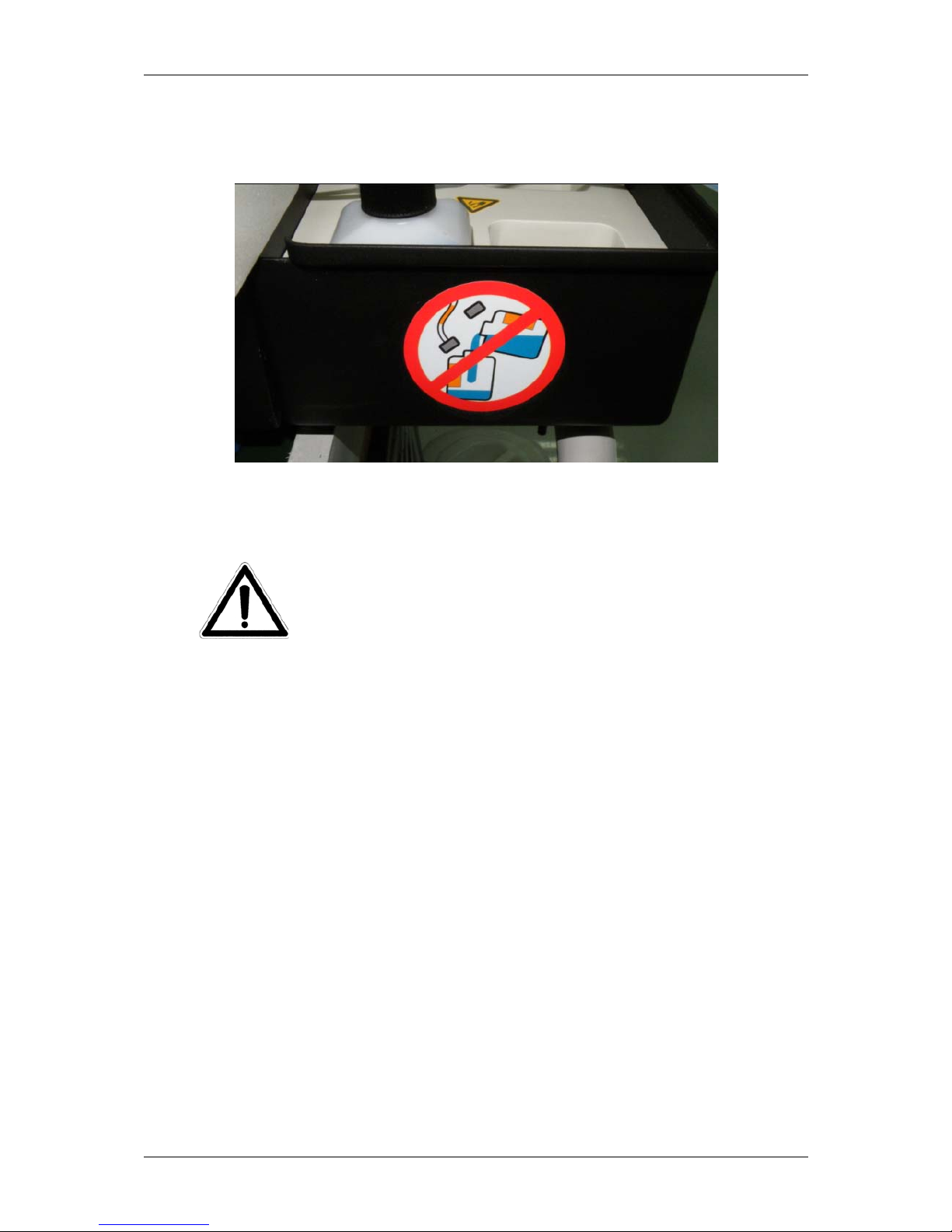
Fig. 8.4-1: Warning Labels on Waste Bag housing
9 Affected processing of MAGLUMI®Diagnostic System
1.For keeping safety and correctness of the
MAGLUMI®Diagnostic System the Daily Maintenance and
System Test with Visual inspection of needle is to be
performed by the user every morning and after each
exchange of starter reagents.
Additionally the Routine weekly maintenance must be
performed by user according to the Operating Instructions.
2.For keeping safety and correctness of the diagnostic results,
the laboratory has to use MAGLUMI®Controls according to
their Information of Use.
3.The Information of Use of the used Diagnostic Kits are to be
followed. The MAGLUMI®Diagnostic System may only be
used under the working conditions defined in this Operating
Instruction.
The detailed cleaning instruction in the Operating Instructions
are to be followed strictly inclusively the choice of disinfectant.
4.Safe and intended function of the MAGLUMI®Diagnostic
System can only be expected with the use of cuvettes,
integrals, disposals and other acessories approved by SNIBE
5.Pooled Starter Systems can cause higher uncertainties in the
creation of the diagnostic results; therefore, Starter Reagents
may never be pooled.
6.Kits with different Starter Reagents may never be mixed on
board of the MAGLUMI®Analyzer.
Operating instructions Page 9
Safety Notes
7.For keeping safety and correctness of the diagnostic results
only new and non contaminated cuvettes may be used.
8.The Handling and Routine Maintenance of the Tubing
System with bleeching liquid is to be done according to the
MAGLUMI® Operating Instructions.
9.All produced diagnostic results should be validated by the
responsible person in the validation menu of the MAGLUMI®
Analyzer before release.
9.1 Common Cautions for Sample Station
1.For keeping safety and correctness of the diagnostic results only
in the Operating Instruction defined Sample Tubes for the applied
racks may be used.
2.The described loading and unloading procedure (never before
green LED is glowing) in the Operating Instruction are to be
followed.
3.The position of Sample Tube is never to be changed after
loading.
9.2 Common Cautions for Reagent station
1.The description of the Integral handling before loading and the
correct loading procedure in the Operating Instruction is to be
followed.
2.For keeping safety and correctness of the diagnostic results the
described handling and never to change the analyzer is to be
followed with once opened Integrals.
3.The upgrade of a Method File may only be realized according
the procedure in the Operating Instruction.
9.3 Common Cautions for Starter Reagents
1.For keeping safety of the users be sure to avoid spilling of
Starter Reagents which can create harm because of their acidity.
2.The instructions in the Operating Instruction for Starter storage,
handling (potentially infectious), installation and operating
conditions, inclusive the expiry date for onboard stability must be
realized.
3.For keeping safety, the Starter Covers are always to be closed
after loading according to the Operating Instruction.
4.The formation of air bubbles is to be avoided.
5.The correct positioning of starter reagents container is to be
assured.
6.The handling, maintenance and daily control of storage containers
of Starter Reagents must be realized according to the Operating
Instruction.
Page 10 Operating instructions
Safety Notes
Fig. 9.3-1: Warning Label on Starter Reagent container on the right side of the analyzer
9.4 Common Cautions for Waste Bag
1.For keeping safety, only Waste Bags approved by SNIBE. may be
used
2.The instructions for loading, handling and disposal of Waste Bag, in
the MAGLUMI
®
Operating Instruction are to be followed..
3.Take care about the Waste Bag and make sure to empty it in time
avoiding process interruptions
9.5 Common Cautions for Wash System
1.Use only MAGLUMI
®
System Liquid concentrate for the
preparation under ambient operating conditions in containers
approved by SNIBE
2.For keeping safety, never use freshly prepared System Liquids,
but never use after defined expiry date for onboard stability.
3.Only degassed System Liquids are to be used.
4.The handling and maintenance requirements of Wash Buffer
system and Wash Station inclusive description of cleaning
process are to be followed.
Operating instructions Page 11
Safety Notes
9.6 Common Cautions for Computer system and Software
Never install Software not released by SNIBE
1. For keeping safety and correctness of the diagnostic results each
Laboratory has to define a hierarchie of Access Rights for the
MAGLUMI®Diagnostic System.
2.The instructions on “Host Connection” in the MAGLUMI® Operating
Instruction are to be followed.
3.The Host Program is not a device manufactured and therefore
not checked for compatibility with the MAGLUMI®Diagnostic
System under the responsibility of SNIBE
There does no warrantee against data safety corruption exist.
10 Working Conditions of MAGLUMI®Analyzer
Operating voltage: Alternating voltage
100 – 120V
200 – 240 V
Frequency 50 / 60 Hz
Power input: MAGLUMI
®
500 VA
PC system 400 VA
Compliance is required with the following ambient conditions
during operation of the MAGLUMI
®
Analyzer:
·Application within buildings (not for outdoor use)
Temperature ranges :
·Equipment safety maintained in the range
5° - 45°C
·Reliability of measurements maintained in
the range 15° - 35°C
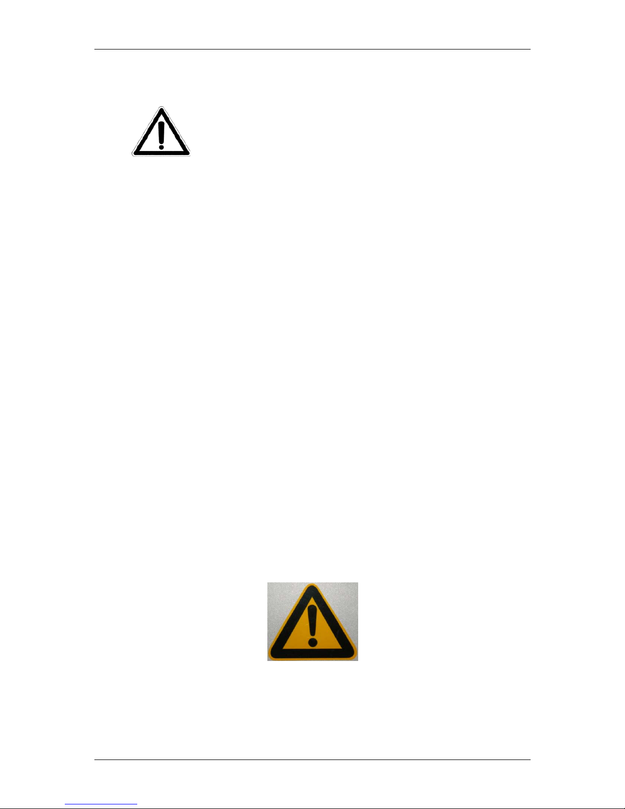
11 Warning Labels on MAGLUMI®Analyzer
Potential Danger that can cause death or serious deterioration of
the state of health of the User. Read Operating Instruction
thoroughly.
Page 12 Operating instructions

Safety Notes
Danger of Electric Shock by Touching Inside of the Analyzer
Danger of Acid Liquids
Danger of Laser Burns
Danger of Laser Burns, additional Information
Danger of potentially infectious biological material
Operating instructions Page 13

Safety Notes
Do not pool Starter Reagents
Page 14 Operating instructions

Operating instructions Content
Content
Page
1. Intended Use 1-1
1.1 Authorization------------------------------------------------------------------------------------------------------------- 2
1.2 Notation------------------------------------------------------------------------------------------------------------------- 2
1.3 Version Information ---------------------------------------------------------------------------------------------------- 2
2. Measuring Principle 2-1
2.1 Test procedure 1-step assay ---------------------------------------------------------------------------------------- 2
2.2 Test procedure 2-step assay ---------------------------------------------------------------------------------------- 3
2.3 Measuring Function description------------------------------------------------------------------------------------- 4
2.4 Measuring principle ---------------------------------------------------------------------------------------------------- 5
2.5 Calibration---------------------------------------------------------------------------------------------------------------- 6
3. System Description 3-1
3.1 An overview of the system components --------------------------------------------------------------------------- 2
3.2 Analyzer--------------------------------------------------------------------------------------------------------------------4
3.2.1 Sample station--------------------------------------------------------------------------------------------------------- 6
3.2.2 Reagent station-------------------------------------------------------------------------------------------------------- 8
3.2.3 Barcode reader and RFID reader--------------------------------------------------------------------------------11
3.2.3.1 Barcode reader --------------------------------------------------------------------------------------11
3.2.3.2 RFID Reader -----------------------------------------------------------------------------------------13
3.2.4 Pipetting system------------------------------------------------------------------------------------------------------14
3.2.5 Incubator ---------------------------------------------------------------------------------------------------------------15
3.2.6 Washer -----------------------------------------------------------------------------------------------------------------16
3.2.7 Measuring chamber -------------------------------------------------------------------------------------------------17
3.2.8 Pump systems--------------------------------------------------------------------------------------------------------18
3.2.9 Stacker------------------------------------------------------------------------------------------------------------------19
3.2.10 Starter reagents-----------------------------------------------------------------------------------------------------22
3.2.11 Supply connections for wash / system liquid ----------------------------------------------------------------24
3.2.12 Disposal---------------------------------------------------------------------------------------------------------------26
3.2.13 Electrical and electronic connections--------------------------------------------------------------------------28
3.3 Computer system-------------------------------------------------------------------------------------------------------29
3.4 Monitor --------------------------------------------------------------------------------------------------------------------30
3.5 Software ------------------------------------------------------------------------------------------------------------------31
3.6 Connecting cables------------------------------------------------------------------------------------------------------32
3.7 Consumables------------------------------------------------------------------------------------------------------------33
4. Installation and Start up 4-1
4.1 Installation of the Equipment----------------------------------------------------------------------------------------- 3
4.1.1 Electrical connections of the system ---------------------------------------------------------------------------- 3
4.1.2 Connecting supply containers for wash / system liquid and waste containers------------------------ 4
4.1.3 Connecting starter reagents (MAGLUMI®Starter Kit)------------------------------------------------------ 4
4.1.4 Fitting the waste bag for reaction modules (MAGLUMI®Waste Bag)---------------------------------- 5
4.1.5 Loading reaction modules------------------------------------------------------------------------------------------ 5
4.2 Switching on and starting the system------------------------------------------------------------------------------ 6
4.2.1 Starting the PC system --------------------------------------------------------------------------------------------- 6
4.2.2 Starting the system at the beginning of the work day------------------------------------------------------- 6
4.2.3 Starting the system at the beginning of the work week----------------------------------------------------- 6
4.2.4 Starting the system after a period of three or more days of inactivity----------------------------------- 7
4.3 Starting the MAGLUMI®software & system--------------------------------------------------------------------- 9
4.4 Shutting down the MAGLUMI®software & system-----------------------------------------------------------10
4.4.1 Shutting down at the end of the work day---------------------------------------------------------------------10
4.4.2 Shutting down at the end of the work week-------------------------------------------------------------------10
4.4.3 Shutting down for 3 or more days inactivity-------------------------------------------------------------------11
4.5 Coordinates-------------------------------------------------------------------------------------------------------------12
4.5.1 Preparation for coordinate:-------------------------------------------------------------------------------------12
Operating instructions Page 1

Operating instructions Content
4.5.2 Steps of Coordinates-----------------------------------------------------------------------------------------------14
4.5.3 Reference positions adjust----------------------------------------------------------------------------------------15
4.5.3.1 Adjustment of the reference left position -----------------------------------------------------15
4.5.3.2 Adjustment of the reference right position----------------------------------------------------16
4.5.4 Left Pipetting Position Adjust-------------------------------------------------------------------------------------17
4.5.4.1 Adjustment of the left needle in left pipetting position-------------------------------------18
4.5.4.2 Adjustment of the right needle in left pipetting position -----------------------------------20
4.5.5 Right Pipetting Position Adjust-----------------------------------------------------------------------------------22
4.5.5.1 Adjustment of the left needle in right pipetting position -----------------------------------23
4.5.5.2 Adjustment of the right needle in right pipetting position ---------------------------------26
4.5.6 Washing position adjust ------------------------------------------------------------------------------------------29
4.5.6.1 Adjustment of the left Washing Position------------------------------------------------------29
4.5.6.2 Adjustment of the Right Washing Position---------------------------------------------------30
4.5.7 Sample area position adjust--------------------------------------------------------------------------------------32
4.5.7.1 Adjustment of the left needle in sample area position-------------------------------------33
4.5.7.2 Adjustment of the right needle in sample area position-----------------------------------36
4.5.8 Reagent area position Adjust ------------------------------------------------------------------------------------39
4.5.8.1 Adjustment of the left needle in reagent area position --------------------------------------------------40
4.5.8.2 Adjustment of the right needle in reagent area position ----------------------------------45
4.5.9 Z-Dispense position adjust----------------------------------------------------------------------------------------50
4.5.9.1 Adjustment of the left needle in Z-Dispense position--------------------------------------51
4.5.9.2 Adjustment of the right needle in Z-Dispense position -----------------------------------52
4.5.10 Z-Start position adjust--------------------------------------------------------------------------------------------53
4.5.10.1 Adjustment of the left needle in Z- Start position------------------------------------------54
4.5.10.2 Adjustment of the right needle in Z- Start position----------------------------------------55
5. Operation and Structure Of The Software 5-1
5.1 Operating the software------------------------------------------------------------------------------------------------ 2
5.2 Structure of the software / main menu----------------------------------------------------------------------------- 3
5.3 Menu items in overview----------------------------------------------------------------------------------------------- 8
6. Menu [System] in detail 6-1
6.1 Menu [System] in overview------------------------------------------------------------------------------------------- 2
6.2 System Functions [Info] in detail------------------------------------------------------------------------------------ 4
6.3 System Functions [Mode] in detail --------------------------------------------------------------------------------- 5
6.4 System Functions [User] in detail----------------------------------------------------------------------------------- 7
6.5 System Functions [Login] in detail---------------------------------------------------------------------------------- 9
6.6 System Functions [Service] in detail------------------------------------------------------------------------------10
6.7 Exiting the MAGLUMI® program ----------------------------------------------------------------------------------12
7. Menu [Definitions] in detail 7-1
7.1 Definitions in overview------------------------------------------------------------------------------------------------- 3
7.2 <Test> icon in detail --------------------------------------------------------------------------------------------------- 4
7.2.1 [Assay Selection] icon, <OK> in detail-------------------------------------------------------------------------- 4
7.2.2 [Assay Selection] icon, <Export> in detail---------------------------------------------------------------------- 5
7.2.3 [Assay Selection] icon, <Import> in detail---------------------------------------------------------------------- 5
7.2.4 [Assay Selection] icon, <TEST> in detail---------------------------------------------------------------------- 7
7.2.5 [Assay Selection] icon, <Edit> in detail ------------------------------------------------------------------------- 8
7.2.5.1 [User Specific Assay Data] – Saving and Canceling --------------------------------------10
7.2.5.2 [User Specific Assay Data] – Information section------------------------------------------10
7.2.5.3 [User Specific Assay Data] – range settings-------------------------------------------------11
7.2.5.4 [User Specific Assay Data] – automatic retesting ------------------------------------------12
7.2.5.4.1 [AutoDilution]-------------------------------------------------------------------------------12
7.2.5.4.2 [AutoReflex]--------------------------------------------------------------------------------14
7.2.5.5 [User Specific Assay Data] – Qualitative result labels, result format, master curve
information-----------------------------------------------------------------------------------------------------15
7.2.5.5.1 <Qualitative Labels>---------------------------------------------------------------------15
7.2.5.5.2 <Format> -----------------------------------------------------------------------------------16
7.2.5.5.3 <MasterCurve>----------------------------------------------------------------------------17
Page 2 Operating instructions

Operating instructions Content
7.2.5.6 [User Specific Assay Data] – frequency of control runs-----------------------------------20
7.3 <Control> icon in detail-----------------------------------------------------------------------------------------------21
7.3.1 [Control Selection] icon, <OK> in detail------------------------------------------------------------------------22
7.3.2 [Control Selection] icon, <Add>, & <Edit> in detail ---------------------------------------------------------23
7.3.2.1 [Control Data Input] – Saving and Canceling------------------------------------------------23
7.3.2.2 [Control Data Input] – control specification---------------------------------------------------24
7.3.2.3 [Control Data Input] – Selection of the assay------------------------------------------------24
7.3.2.4 [Control Data Input] – Control detailed descriptions ---------------------------------------25
7.3.2.4.1 [Control Data Input] – Control detailed descriptions------------------------------26
7.3.2.5 [Control Data Input] – Procedure for adding a control-------------------------------------28
7.3.3 [Control Selection] icon, <Delete> in detail -------------------------------------------------------------------28
7.4 <Group> icon in detail------------------------------------------------------------------------------------------------29
7.4.1 [Group Selection] icon, <OK> in detail-------------------------------------------------------------------------30
7.4.2 [Group Selection] icon, <Add>, <Insert>, <Edit>, & <Copy> in detail----------------------------------30
7.4.2.1 [Group Selection] – saving and canceling----------------------------------------------------31
7.4.2.2 [Group Selection] – [Selected Assay] ---------------------------------------------------------31
7.4.2.3 [Group Selection] – Assay Selection ----------------------------------------------------------32
7.4.2.4 [Group Selection] – [Assay Group]-------------------------------------------------------------33
7.4.2.5 [Group Selection] – Procedure for assigning an assay to an existing group---------33
7.4.2.6 [Group Selection] – Procedure for assigning a new group to the database----------34
7.4.2.7 [Group Selection] – Procedure for inserting a new group to the database-----------35
7.4.2.8 [Group Selection] – Procedure for copying an existing group to the database------35
7.4.3 [Group Selection] icon, <Delete> in detail---------------------------------------------------------------------36
7.5 <Profile> icon in detail------------------------------------------------------------------------------------------------37
7.5.1 [Profile Selection] icon, <OK> in detail-------------------------------------------------------------------------38
7.5.2 [Profile Selection] icon, <Add>, <Edit>, & <Copy> in detail-----------------------------------------------38
7.5.2.1 [Profile Selection] – saving and canceling----------------------------------------------------39
7.5.2.2 [Profile Selection] – Assay Selection ----------------------------------------------------------40
7.5.2.3 [Profile Selection] – Profile list ------------------------------------------------------------------41
7.5.3 [Profile Selection] icon, <Delete> in detail --------------------------------------------------------------------41
7.6 <Sender> icon in detail-----------------------------------------------------------------------------------------------42
7.6.1 [Sender Selection] icon, <OK> in detail------------------------------------------------------------------------43
7.6.2 [Sender Selection] icon, <Add>, <Edit>, & <Copy> in detail ---------------------------------------------43
7.6.3 [Sender Selection] icon, <Delete> in detail -------------------------------------------------------------------45
7.7 <Dilut. > Icon in detail-------------------------------------------------------------------------------------------------46
7.7.1 [Dilution Definition] – saving and canceling-------------------------------------------------------------------47
7.7.2 [Dilution Definition] – Assay --------------------------------------------------------------------------------------48
7.7.3 [Dilution Definition] – Assay Selection -------------------------------------------------------------------------48
7.7.4 [Dilution Definition] – Dilution Selection------------------------------------------------------------------------49
7.7.5 [Dilution Definition] –Selected Dilutions------------------------------------------------------------------------50
7.7.5.1 [Selected Dilutions] - <Edit> in detail----------------------------------------------------------50
7.7.5.2 [Selected Dilution] - <Delete> in detail--------------------------------------------------------51
7.7.6 <Dilute > How to set a dilution-----------------------------------------------------------------------------------52
8. Menu [Process] in detail 8-1
8.1 Process in overview---------------------------------------------------------------------------------------------------- 2
8.2 <Init> icon ---------------------------------------------------------------------------------------------------------------- 2
8.2.1 <Init> icon <Yes> in detail ----------------------------------------------------------------------------------------- 3
8.2.2 <Init > icon <No> in detail------------------------------------------------------------------------------------------ 4
8.3 <Continue> icon -------------------------------------------------------------------------------------------------------- 4
8.4 <Low Level> icon------------------------------------------------------------------------------------------------------- 5
8.4.1[Low Level Command] icon <Send> in detail ------------------------------------------------------------------ 5
8.4.2[Low Level Command] icon <OK> in detail--------------------------------------------------------------------- 6
8.4.3[Low Level Command] icon <Cancel> in detail---------------------------------------------------------------- 6
8.5. <Protocol> icon--------------------------------------------------------------------------------------------------------- 6
8.5.1 [Protocol File Name] icon <OK> in detail----------------------------------------------------------------------- 7
8.5.2 [Protocol File Name] icon <Cancel> in detail------------------------------------------------------------------ 7
8.5.3 Initiating a Protocol -------------------------------------------------------------------------------------------------- 7
9. Menu [System Test] in detail 9-1
Operating instructions Page 3

Operating instructions Content
9.1 System Test in overview---------------------------------------------------------------------------------------------- 2
9.2 System Test in detail -------------------------------------------------------------------------------------------------- 3
9.2.1 [System Test] dialog [Priming] section in detail--------------------------------------------------------------- 3
9.2.2 [System Test] dialog [System test] section in detail --------------------------------------------------------- 4
9.2.3 [System Test] dialog exiting, confirmation, and information ----------------------------------------------- 5
9.3 Placing Light Check on the analyzer------------------------------------------------------------------------------- 7
9.3 1 Manual programming of the Light Check on the analyzer-------------------------------------------------- 7
10. Menu [Results] in detail 10-1
10.1 Results in overview--------------------------------------------------------------------------------------------------- 2
10.2 <Valid> icon in detail------------------------------------------------------------------------------------------------- 3
10.2.1 [Valid Result Journal] icon, <Sort> in detail------------------------------------------------------------------ 4
10.2.2 [Valid Result Journal] icon, <OK> in detail------------------------------------------------------------------- 5
10.2.3[Valid Result journal] icon <Print> in detail-------------------------------------------------------------------- 5
10.2.4 [Valid Result Journal], icon <Online> in detail--------------------------------------------------------------- 6
10.2.5 [Valid Result Journal] icon <View> in detail------------------------------------------------------------------ 7
10.2.6 [Valid Result Journal], icon <Delete> in detail--------------------------------------------------------------- 9
10.3 <Journal> icon in detail---------------------------------------------------------------------------------------------- 9
10.3.1 [Daily Lab - Journal] icon <Sort> in detail -------------------------------------------------------------------11
10.3.2 [Daily Lab - Journal] icon <OK> in detail---------------------------------------------------------------------12
10.3.3[Daily Lab - Journal] icon <Print> in detail--------------------------------------------------------------------12
10.3.4[Daily Lab - Journal] icon <Recalc.> in detail----------------------------------------------------------------13
10.3.5 [Daily Lab - Journal] icon <Online> in detail ----------------------------------------------------------------14
10.3.6 [Daily Lab - Journal] icon <Edit> in detail--------------------------------------------------------------------14
10.3.6.1 [Daily Lab - Journal -> Detailed Sample Result] -> Change RLU---------------------15
10.3.7 [Daily Lab - Journal] icon <Delete> in detail ----------------------------------------------------------------16
10.3.8[Daily Lab - Journal] icon <Valid> in detail-------------------------------------------------------------------17
10.4 [Control] icon in detail-----------------------------------------------------------------------------------------------17
10.5 [Calibrator] icon in detail--------------------------------------------------------------------------------------------19
10.5.1 [Calibrators Result Journal] icon <View> in detail---------------------------------------------------------20
10.6 [QC] icon in detail----------------------------------------------------------------------------------------------------21
10.7 [System Test] icon in detail----------------------------------------------------------------------------------------21
11. Menu [Patients] in detail 11-1
11.1 [Patients] in overview ------------------------------------------------------------------------------------------------ 2
11.2 [Sample Loading] dialog in detail --------------------------------------------------------------------------------- 3
11.2.1 [Rack Station] in detail -------------------------------------------------------------------------------------------- 3
11.2.2 [Sample- ID] in detail ---------------------------------------------------------------------------------------------- 5
11.2.2.1 [Sample- ID] Double Blind Entry..............................................................................6
11.2.3 [Assay Group/ Assay List]---------------------------------------------------------------------------------------- 7
11.2.3.1 How to assign a single assay to a single patient sample........................................8
11.2.3.2 How to assign a single assay to all displayed patient samples “Copy function”.....8
11.2.4 [Profile Selection] in detail---------------------------------------------------------------------------------------- 9
11.2.5 [Loading] in detail--------------------------------------------------------------------------------------------------10
11.2.5.1 [Loading] icon <Entire>, & <Edit> in detail ............................................................11
11.2.5.2. [Loading] icon <STAT> in detail ...........................................................................12
11.2.5.3 [Loading] icon <Control> in detail..........................................................................13
11.2.5.4 [Loading] icon <Std/LC> Double Blind Entry.........................................................15
11.2.5.5 [Loading] icon <Patient>........................................................................................17
11.2.5.5.1 [Patient] icon <Sender> .............................................................................18
11.2.5.6 [Loading] icon <Dilute> in detail ............................................................................19
11.2.6 exiting and confirmation------------------------------------------------------------------------------------------21
11.2.6.1 [Sample Loading] dialog, <OK> icon.....................................................................21
12. Menu [Reagents] in detail 12-1
12.2 [Reagent Loading] dialog in detail -------------------------------------------------------------------------------- 2
12.2.1 [Reagent Integral Area] section in detail---------------------------------------------------------------------- 3
12.2.1.1 [Reagent Integral Area] numbered integral position color definition .......................4
12.2.1.2 [Reagent Integral Area] integral symbol definitions.................................................4
Page 4 Operating instructions
Other manuals for Maglumi 2000
1
Table of contents
Popular Measuring Instrument manuals by other brands

Siemens
Siemens SITRANS F operating instructions

Precision Digital Corporation
Precision Digital Corporation Helios PD2-6300 instruction manual

Campbell
Campbell CR23X Operator's manual

Omicron
Omicron CMC 156 Reference manual

Hanna Instruments
Hanna Instruments HI 8014 instruction manual

Masimo
Masimo PRONTO-7 Operator's manual


