Sno-Pro 1SP7 Quick start guide

HOME-PRO 3000
Curtis Industries Inc. LLC, 111 Higgins St., Worcester, MA 01606 TEL: (800) 343-7676 FAX: (508) 854-3377 For Parts and information visit us at www.Curtisindustries.net
Curtis Industries Inc. LLC, reserves the right to change product design or specifications without notice or liability.
Curtis Snow Plows are protected by the following U.S. Patent Numbers: 6,145,222 and 6,209,231 Licensed under U.S. Patent Number 5,568,694 & Canadian Patent Number 2,137,853.
Other patents pending.
Home-Pro 3000 Series Polymer Moldboard Plow
7' Moldboard PN: 1SP7 ● 7-1/2' Moldboard PN: 1SP75HP
1 of 25
Assembly and Mounting Instructions - May 2010
2 of 25
Curtis Plows are simple by design. Our unit utilizes an A-Frame assembly for mounting the Electric/Hydraulic unit.
This exclusive Curtis feature eliminates the need for Hydraulic Quick-disconnects and also "Hides-Away"
our Power unit. Our A-Frame assembly takes the weight of the Power unit off the Lift Frame assembly and allows for
increased airow to the Radiator. Curtis uses State of the Art techniques for t and consistency such as an Automated
Conveyor System, Robotic Welding, High Denition Plasma and Hydraulic Press Brakes.
We feel these techniques are very important for overall quality and serviceability.
To help our customers understand the loads being imposed on their vehicles as well as the importance of ballast in
some applications, we also incorporate computer modeled weight distributions. Some vehicles may require "Helper
Springs", "Air Shocks" or similar devices to compensate for the added weight of the Plow equipment.
This information is available upon request. From all of us at Curtis, Thank you for choosing our products!
► Install any additional required equipment rst, such as Snow tires, Helper Springs, Lights, etc.
► Read and understand this manual before beginning Plow assembly.
► Check Carton contents prior to beginning Plow assembly.
► Work in an organized area large enough to pull vehicle up to Plow for nal attachment.
► Have your tools ready prior to assembly, it will speed up the assembly time.
IMPORTANT: Before you Start...
1. Always disconnect vehicle battery when working with vehicle-side wiring.
2. Plow assembly requires handling of many heavy parts. Be sure to handle
with care. Use proper tooling, equipment and assistance where indicated.
Required Tools Content Checklist for 2 Cartons:
■ 1/2" Drive Ratchet
■ 3/8" Drive Ratchet
■ 15/16" Deep Socket & Wrench
■ 3/4" Socket & Wrench
■ 5/8" Wrench
■ 9/16" Socket
■ 9/16" Wrench (2)
■ 1/2" Socket & Wrench
■ Pliers or Vice-Grips
■ Wire Cutters
■ Hammer or Mallet
■ 10" or 12" Adjustable Wrench
■ 1-1/8" Open End Wrench
■ Low Temperature Grease
Plow Package #1:
● Trip Frame (1TBP22C)
● Lift Frame Assembly (1TBP38D)
Plow Package #2:
● A-Frame Assembly with Angle Pistons
● Light Kit (set of 2) (1TBP39H)
● Hardware Box #1
● Hardware Box #2
● Truck-Side Harness with Plug Storage Holder
● Blade Markers (set of 2) (1TBP37)
Shipped with Cartons:
● Moldboard complete with Cutting Edge
CAUTION
3 of 25
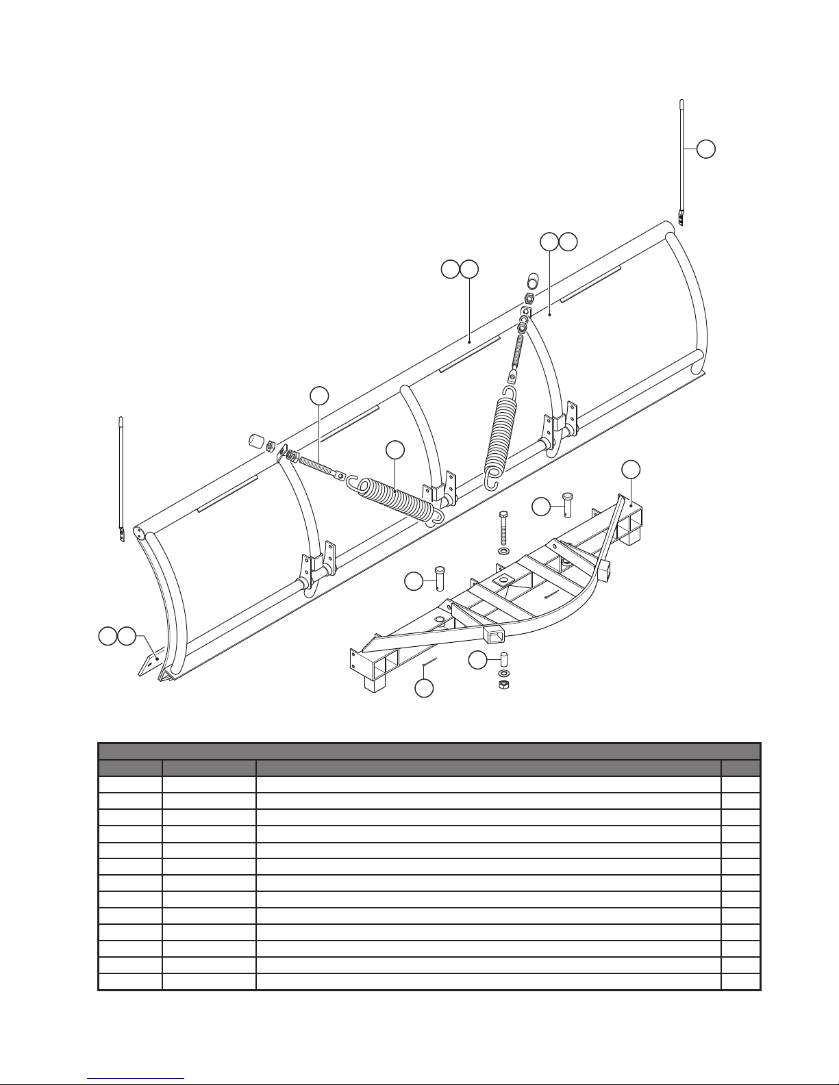
Home-Pro 3000 Illustrated Parts List - Moldboard & Trip Frame
13
7
6
1
9
5
8
10
9
1211
2
3 4
Moldboard/Trip Frame Parts List
Ref # Item # Item Description Qty.
1 1TBP21I 7' HOME-PRO MOLDBOARD 1
2 1TBP21K 7.5' HOME-PRO MOLDBOARD 1
3 1TBP124 HOME-PRO MOLDBOARD SKIN HMW PLASTIC - 7' 1
5 1TBP37 BLADE MARKER 2
6 1TBP34 SPRING EYEBOLT 5/8"-11 X 7 2
7 BUY LOCALLY 3/16" X 2" COTTER PIN 2
8 1TBP22C TRIP FRAME ASSEMBLY (HOME-PRO) 1
9 1TBP23 1" X 4" CLEVIS PIN 2
10 1TBP127 TRIP FRAME PIVOT PIN HOME-PRO 3000 (3-7/8" LONG) 1
11 1TBP49I 7' CUTTING EDGE 1
12 1TBP49K 7-1/2' CUTTING EDGE 1
13 1TBP33 TRIP SPRING 2
4 1TBP124-90HP HOME-PRO MOLDBOARD SKIN HMW PLASTIC - 7.5' 1

Home-Pro 3000 Illustrated Parts List - A-Frame & Harness
4 of 25
1
23
5 6
11
11
14
14
13
4
10
Apply Grease
10
9
15
7
20
21
8
12
17
18
19
28 22
24
25
26
23 30
27
Inside A-Frame
TRUCK SIDEPLOW SIDE
16
Apply Grease
29

Home-Pro 3000 Illustrated Parts List - A-Frame & Harness
8SV-TBP117-B5 A-FRAME BOTTOM JACK COVER 1
1TBP53 HI-AMP BATTERY HARNESS 1
A-Frame/Harness Parts List
Ref # Item # Item Description Qty.
1TBP29C A-FRAME ASSEMBLY COMPLETE 1
21TBP58A A-FRAME COVER, SnoPro 3000 1
31TBP30 5/16" x 24" CHAIN 1
41TBP31 5/16" ANCHOR SHACKLE 1
51TBP100 A-FRAME JACK SWITCH 1
61TBP100A TOGGLE SWITCH BOOT 1
71TBP106 JACK LEG 1
81TBP128 A-FRAME HOSE GROMMET 3
91TBP129 HARNESS (SPIRAL) WRAP, 16" LENGTH 1
1TBP27 10" ANGLE PISTON 2
1TBP73 1" x 3" CLEVIS PIN 2
1UHJA JACK ADAPTER 3000 SERIES (HYD JACK ONLY) 1
13
10
11
12
1TBP98F 90 DEG. BRASS BAR STREET ELBOW 1
14 1TBP98G 90 DEGREE ELBOW 2
15 1UHP UNIVERSAL HARNESS-PLOW SIDE 1
16
17
18
19
1UHT UNIVERSAL HARNESS-TRUCK SIDE 1
1TBP95 3" JACK CYLINDER 1
1TBP96 6" JACK SPRING 1
1TBP111 JACK SPRING GUIDE ROD 1
20 BUY LOCALLY 5/8"-11 x 4-1/2" GRADE 5 HEX BOLT 1
21
22
23
24
25
26
27
28
BUY LOCALLY 5/8"-11 NYLON LOCKNUT 1
1TBP48A LIGHT SWITCH FOR TRUCK PLOW 1
1TBP62 #4 CABLE 90" 1
1TBP136 VEHICLE SIDE CONTROL WEATHER CAP 1
1TBP140 LOCK PIN STORAGE HOLDER & LANYARD 1
1TBP141 HARNESS LOCK PIN (SET OF 5) 1
1TBP54 HI-AMP WEATHER CAP 1
1TBP61A 12V MOTOR SOLENOID 1
18SV-NAFW-B5 A-FRAME ASSEMBLY - FRAME ONLY 1
29
30
5 of 25

6 of 25
Home-Pro 3000 Illustrated Parts List - Lift Frame
W
A
R
N
I
N
G
22
9
20
4
2
1
12 10
11
12
6
7
13
8
8
17
15
14
16
19
18
21
5
3

7 of 25
Home-Pro 3000 Illustrated Parts List - Lift Frame
Lift Frame Parts List
Ref # Item # Item Description Qty.
1TBP38D LIFT FRAME HOME PRO 7' & 7.5' COMPLETE 1
1 8SV-TBP114A-B5 DRIVER'S SIDE LATCH HOOK HOME-PRO 1
2 8SV-TBP115A-B5 PASSENGER'S SIDE LATCH HOOK HOME-PRO 1
3 1TBP107 SNAP LOCK HANDLE (INCLUDED IN 9SV-SLH KIT) 2
4 1TBP33B SNAP LOCK SPRING (INCLUDED IN 9SV-SLH KIT) 2
5 1TBP103 PLASTIC HANDLE FOR SNAP LOCK SP3000 (INCLUDED IN 9SV-SLH KIT) 2
6 1TBP112A LIFT FRAME SIDE PLATE, LH SNO-PRO 3000 (INCLUDED IN 8SV-TBP112-B5 KIT) 1
7 1TBP112B LIFT FRAME SIDE PLATE, RH SNO-PRO 3000 (INCLUDED IN 8SV-TBP112-B5 KIT) 1
8
1TBP39H PLOW LIGHT KIT, DUAL HALOGEN LAMPS W/SWITCH KIT (2 HEAD LAMPS) 1
9 1TBP161 PLOW LIGHT MOUNTING HARDWARE 1
10 1TBP33A-1 TORSION SPRING, LH SNO-PRO 3000 (INCLUDED IN 9SV-TBP33A KIT) 1
11 1TBP33A-2 TORSION SPRING, RH SNO-PRO 3000 (INCLUDED IN 9SV-TBP33A KIT) 1
12 1TBP113 TORSION SPRING BUSHING (INCLUDED IN 9SV-TBP33A KIT) 2
13 1TBP40 LIFT ARM 1
14 1TBP108 1" x 4-1/2" CLEVIS PIN 1
15 1TBP42 3/4" x 4-1/2" CLEVIS PIN 1
16 1TBP43 3/4" x 2-3/4" CLEVIS PIN 1
17 1TBP44A 7-1/2" LIFT PISTON 1
18 1TBP98H 45 DEGREE ELBOW FOR LIFT PISTON 1
19 1TBP109 1" PISTON SPACER 2
20
21
1TBP135 PLUG STORAGE HOLDER 1
1TBP159 SNAP LOCK CROSS BOLT WITH BUSHING AND NUT 2
22 1TBP97 PLASTIC HANDLE COVER (NOT ORDERABLE) 2
Ref #
3,4,5
ORDERABLE AS KITS - NOT SEPARATELY
9SV-SLH SNAP LOCK HANDLE KIT (KIT INCLUDES 2 HANDLES, 2 SPRINGS, 2 HANDLE COVERS) 1
6,7 8SV-TBP112-B5 LIFT FRAME SIDE PLATE KIT, SNO-PRO 3000, (KIT INCLUDES L&R PLATES) 1
10,11,12 9SV-TBP33A TORSION SPRING KIT (SIDE PLATE TORSION SPRINGS & BUSHINGS, SET OF 2) 1

8 of 25
Home-Pro 3000 Illustrated Parts List - Hydraulics
KTI Hydraulics - Aluminum End Head
29
25
7
1
23
6
89 10 11
5
12
32
26
16
14 19
19
17
3
2
13
36
1
33 24
34
23
30
27
37
31
16
23
22
21
20
28
18
42
39
25
44
43
40
41
38
2
35
SPX Hydraulics
4
OLD
STYLE
NEW
STYLE
2
25
OLDER
MODELS ONLY

9 of 25
Home-Pro 3000 Illustrated Parts List - Hydraulics
Hydraulics Parts List
Ref # Item # Item Description Qty.
1 1TBP59APC HYDRAULIC POWER UNIT COMPLETE W/MANIFOLD, VALVES & COILS 1
2 1TBM8 DC MOTOR 12V - DUAL POST 1
3
1TBP59AP1 HYDRAULIC PUMP ASSEMBLY WITHOUT VALVES & COILS, SNO PRO 1
14 1TBM201 3P3W TANDEM CENTER ANGLE VALVE W/10 VOLT COIL KIT
15 1TBM202 3P3W OPEN CENTER LIFT/JACK VALVE W/10 VOLT COIL KIT
16 1TBM203 2P2W NC ZERO LEAK JACK RETRACT VALVE W/10 VOLT COIL KIT
17
27
31
37
1TBM204 2P2W NC ZERO LEAK FLOAT VALVE W/12 VOLT COIL KIT
18 1TBP98A JACK HOSE - 26-1/2"
19 1TBP98B LIFT HOSE - 37.5"
110 1TBP98C RIGHT ANGLE HOSE - 19"
111 1TBP98D LEFT ANGLE HOSE - 28"
112 1TBP98E BLOCK ADAPTER FOR JACK HOSE
SPX Hydraulics
13 1TBM12 PUMP TO MOTOR COUPLING SPX 1
14 1TBM13 PUMP ASSEMBLY - SPX 1
16 1TBM14 PUMP O-RING KIT (NOT ORDERABLE SEPARATELY) 1
17 1TBM16 PUMP MOUNTING BOLT (NOT ORDERABLE SEPARATELY) 2
18 1TBM17 BOLT - SUCTION COVER 5/16" (INCLUDED IN 9SV-FLT FILTER KIT) 1
19 1TBM15 WASHER FLAT (INCLUDED IN 9SV-FLT FILTER KIT) 1
20 1TBM18 SCREW TAPTITE M6 x 12mm (INCLUDED IN 9SV-FLT FILTER KIT) 1
21 1TBM19 PLUMBING ASSEMBLY INLET (INCLUDED IN 9SV-FLT FILTER KIT) 1
22 1TBM20 FILTER (INCLUDED IN 9SV-FLT FILTER KIT) 1
23 1TBM21 COLLECTOR MAGNET (INCLUDED IN 9SV-FLT FILTER KIT) 1
24 1TBM29 SUCTION COVER (INCLUDED IN 9SV-FLT FILTER KIT) 1
25 1TBM23A RESERVOIR - SNO-PRO 3000 W/ MTNG SCREWS (INCLUDED IN 9SV-RES KIT) 1
26 1TBM11 SPX RESERVOIR O-RING (INCLUDED IN 9SV-RES KIT) 1
1TBP63B RESERVOIR CAP - INTERNAL (3/8" BRONZE) (INCLUDED IN 9SV-RES KIT) 1
28 1TBM22 RESERVOIR SCREW (Set of 4) (INCLUDED IN 9SV-RES KIT) 1
1
1
1
29 1TBP63A RESERVOIR CAP - SNO-PRO 3000 EXTERNAL
1
30 1TBM25 FIXED RELIEF VALVE ASSEMBLY - (SPX OLD STYLE - USE 1TBM25A)
1
1TBM25A FIXED RELIEF VALVE - CARTRIDGE STYLE - (SPX NEW STYLE)
1
32 1TBM26 RETURN TUBE
1
33 1TBM27 COMPRESSION NUT (NOT ORDERABLE SEPARATELY)
1
34 1TBM28 COMPRESSION SLEEVE (NOT ORDERABLE SEPARATELY)
1
35 1TBM30 MOTOR BRUSH KIT (NOT ORDERABLE SEPARATELY)
36 1TBM31 END HEAD (NOT ORDERABLE SEPARATELY)
1TBM32 RESERVOIR DRAIN PLUG
1
1
KTI Hydraulics
1
38 1TBM13A PUMP ASSEMBLY - KTI
1
39 1TBM12A MOTOR TO PUMP COUPLING KTI
1
40 1TBM24 3/8" NPT FEMALE TO FEMALE PLASTIC STREET ELBOW
41 1TBM20 FILTER
1
42 1TBM37 FIXED RELIEF VALVE - CARTRIDGE STYLE - KTI
1
43 1TBM11A KTI RESERVOIR O-RING
44 1TBM21 COLLECTOR MAGNET
11TBP59AP2 MANIFOLD BLOCK ASSEMBLY WITH VALVES & COILS, SNO PRO
ORDERABLE AS KITS - NOT SEPARATELY
18 → 24 9SV-FLT HYDRAULIC PUMP FILTER KIT 1
25 → 28 9SV-RES HYDRAULIC POWER UNIT RESERVOIR KIT 1

10 of 25
Home-Pro 3000 Assembly Instructions
Section 1. Moldboard Assembly
A.) Lay Moldboard on its face. Place cardboard under the Top Tube to prevent paint damage.
B.) Bolt the Trip Frame to the Moldboard at the (6) Pivot Brackets. Figure 1.
Figure 1. Bolt Trip Frame to Moldboard
Section 2. Mount Trip Springs
A.) Mount (2) Trip Springs (1TBP33) to Trip
Frame.
B.) Thread (1) 5/8" Jam Nut half-way onto each
Spring Eyebolt. Figure 2.
C.) Slide (1) 5/8" Lock Washer onto each Spring
Eyebolt (1TBP34) and then insert each Eye
bolt into the Spring Brackets on Moldboard.
D.) Thread (1) 5/8" Locknut onto each Eyebolt.
E.) Tighten Locknuts to increase tension on
Springs until there is enough space between
the coils to slide a piece of paper.
F.) Tighten each 5/8" Jam Nut and Lock Washer
against each Moldboard Spring Bracket to
lock the Eyebolts.
G.) Install Protective End Caps to Eyebolts.
Figure 2. Mount Trip Springs
3/8"-16 x 1" Bolts
Moldboard
Trip Frame
3/8"-16 Lock Nuts
Note direction of Hardware when mounting.
Tighten Jam Nuts on Eyebolts until
correct Spring tension is achieved End
Cap
End
Cap
A B
Thread Jam Nut halfway &
add Lock Washer before inserting
through Moldboard Bracket
11 of 25
Home-Pro 3000 Assembly Instructions
1" x 3-7/8" Hollow Pin
1/2"-13 x 5" Bolt
1/2" Flat Washer
1/2" Flat Washer
1/2"-13 Lock Nut
NOTE:
2-PERSON LIFT
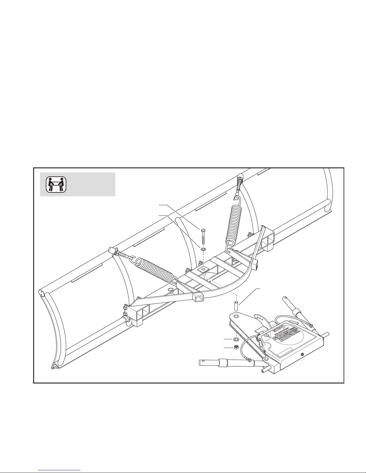
Section 3. Mount A-Frame to Trip Frame
A.) With Moldboard remaining face down, lift A-Frame assembly over the Trip Frame (with assistance,
A-Frame is very heavy) and lower it into the center hole of Trip Frame. Apply grease and install (1)
1" x 3-7/8" Hollow Pin (1TBP127) through the Trip Frame and A-Frame. With Hollow Pin in position,
install (1) 1/2"-13 x 5" Bolt with a Flat Washer down through the Hollow Pin. Fasten loosely with a 1/2"
Flat Washer and Lock Nut, Do not fully tighten at his time. See Figure 3 below.
B.) Swing A-Frame to Left or Right and align hole in Angle Cylinder Ram with corresponding hole in Trip
Frame. Install (1) 1" x 4" Clevis Pin (1TBP23) through Trip Frame and Angle Cylinder Ram.
Secure Clevis Pin with (1) 3/16" x 2" Cotter Pin (1TBP24). Swing A-Frame to opposite side and
repeat alignment and pinning procedure. See Figure 4.
C.) Swing A-Frame back to center position and torque the 1/2"-13 Lock Nut (installed in Step A.)
to 75 ft/lbs. Do not over tighten, the A-Frame must pivot freely.
Figure 3. Mount A-Frame to Trip Frame

Home-Pro 3000 Assembly Instructions
12 of 25
Figure 4. Connect Angle Ram Cylinders to Trip Frame
S
w
i
n
g
A
-
F
r
a
m
e
L
&
R
t
o
i
n
s
e
r
t
P
i
n
s
1" x 4" Clevis Pin
1" x 4" Clevis Pin
3/16" x 2"
Cotter Pin
Section 4. Lift Frame Side Plate Install
A.) Locate both L&R Lift Frame Side Plates (1TBP112A&B) and slide (1) onto each side of the A-Frame
Hinge Pin. Figure 5.
B.) Slide the L&R Torsion Springs (1TBP33A-1 & 1TBP33A-2) over Hinge Pins with the 90º bent ends
inside the hole in the Spring Keeper on the corresponding Side Plate. The straight Spring Legs should
be resting on the A-Frame Spring Stop. Refer to Figures 5 on the next page & Figure 8 on page 15.
C.) Install Torsion Spring Bushings (1TBP113) through the Torsion Springs and over the Hinge Pins.
Fasten loosely with (1) 1/2"-13 x 1" Patch Bolt and 1/2" Flat Washer threaded into each Hinge Pin to
secure the assemblies. Do Not tighten Bolts at this time. Repeat procedure on opposite side.
D.) Using the A-Frame as a lever, grasp the A-Frame near the Side Plates at the top of the assembly and
pull back, raising the Moldboard to the vertical position.
E.) Secure one end link of the Lift Chain to the middle hole in the Chain Bracket on the A-Frame
using (1) 5/16" Chain Shackle supplied in Plow Hardware Bag. See Figure 6.
The 3 mounting holes are used to ne-tune the attachment and lifting
performance of the Plow on a specic vehicle. The middle hole is a good
starting point.
F.) Install (1) Blade Marker at each end of Moldboard Top Tube using hardware supplied with Blade
Markers. Figure 6.
NOTE

13 of 25
Home-Pro 3000 Assembly Instructions
Figure 5. Lift Frame Side Plate Installation
Right
Lift Frame
Side Plate
Left
Lift Frame
Side Plate
Torsion Spring
and Bushing
Torsion Spring
and Bushing
Figure 6. Attach Lift Chain and Mount Blade Markers
Chain Shackle
Mount Blade Markers
Cotter Pin
14 of 25
Home-Pro 3000 Assembly Instructions
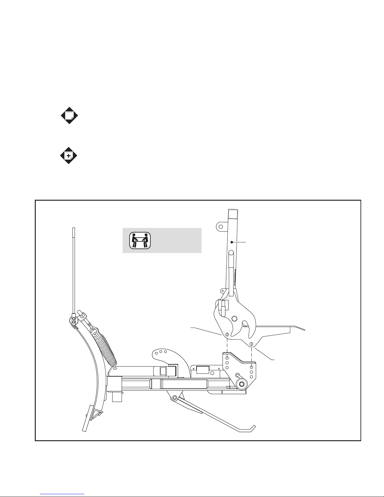
Figure 7. Mount Lift Frame to A-Frame Side Plates
Align on both sides
of Lift Frame and secure
with 5/8" Bolts
Align on both sides of Lift Frame
and secure with 5/8" Bolts
Lift Frame
2-PERSON LIFT
Section 5. Mount Lift Frame to A-Frame Side Plates
A.) With assistance, position Lift Frame to Side Plates and mount with (4) 5/8"-18 x 1-3/4" Bolts and
5/8"-18 Lock Nuts. To provide proper clearance, 5/8" Bolts must be installed from the inside of Lift
Frame with Lock Nuts located on the outside of Lift Frame. This is necessary to provide proper
clearance. Tighten 5/8" Gr.8 fasteners mounting the Lift Frame to 225 ft./lbs., then fully tighten the
Patch Bolts retaining the Side Plates to 55 ft/lbs. Refer to Figures 7 & 8.
The Side Plates have (3) sets of holes that can be used for mounting the Lift Frame.
Refer to Page 19 for information on determining hole locations.
Installing the Lift Frame in the incorrect holes will affect the attachment and
removal of the Plow to the vehicle.
When setting up the Plow for the rst time, adjust the Plow Chain so that the Lift
Frame Attaching Forks are parallel to the A-Frame. Once Plow is set-up correctly,
index the Chain for future reference. Due to variations from truck to truck, one
link adjustments may be necessary to ne tune the individual Plow to a specic
vehicle.
NOTE
ADDITIONAL
NOTES

Home-Pro 3000 Assembly Instructions
15 of 25
Figure 8. Lift Frame Mounting Reference View
Torsion Spring Bushing
1/2" Patch Bolt
Left Side Shown
Lift Frame Side Plate
5/8" Locknuts installed
on Outside of Lift Frame
Spring Keeper on Side Plate
Torsion Spring
A-Frame Spring Stop
Section 6. Lift Frame Setup
A.) Mount Lift Arm (1TBP40) to Upper Mounting Tabs of Lift Frame as shown in Figure 9A. Lift Arm
mounts with (1) 3/4" x 4-1/2" Clevis Pin (1TBP42) and is secured with a 2" Cotter Pin.
B.) Locate Lift Cylinder (1TBP44A) and mount to front of Lift Arm with 1" Piston Spacers (1TBP109).
The 1" x 4-1/2" Clevis Pin (1TBP108) will pass through the Piston Spacers and Lift Cylinder and will be
secured with a 2" Cotter Pin. As shown in Figure 9A.
The Hose Port on the Lift Cylinder must face towards the Driver’s Side.
C.) With top of Lift Cylinder secured, raise the Lift Arm and swing the Lift Cylinder bottom between
Lower Mounting Tabs on the Lift Frame and secure with a 3/4" x 2-3/4" Clevis Pin (1TBP43) and a
2" Cotter Pin to secure the Clevis Pin. Figure 9B.
D.) The Hydraulic Hose should now be connected to the 45º Elbow. Use (2) 9/16" Wrenches when tightening
Lift Hose to avoid twisting the Hose.
E.) Mount Lights to Lift Frame using supplied hardware (1TBP161) and Harness Plug Storage Holder
(1TBP135). See Figure 10.
NOTE
16 of 25
Home-Pro 3000 Assembly Instructions
Figure 9. Lift Arm Mounting
3/4" x 4-1/2"
Clevis Pin
Secure
with Cotter Pin
Insert Clevis Pin
through 1" Piston
Spacers when mounting
Lift Cylinder
Point Hose Port toward A-Frame
Insert Cylinder End
through Lift Frame Tabs
and secure with Cotter Pin
3/4" x 2-3/4"
Clevis Pin
Cotter Pin
1" x 4-1/2"
Clevis Pin
A B
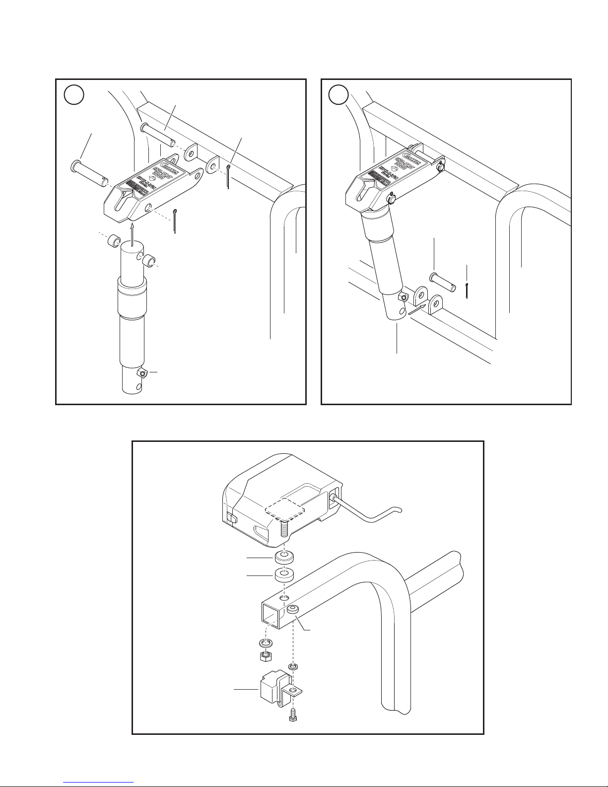
Figure 10. Headlight Mounting
Metal Adjustment Cup
Rubber Vibration Mount
Threaded Insert
Harness Plug
Storage Holder
on Driver’s Side
as shown
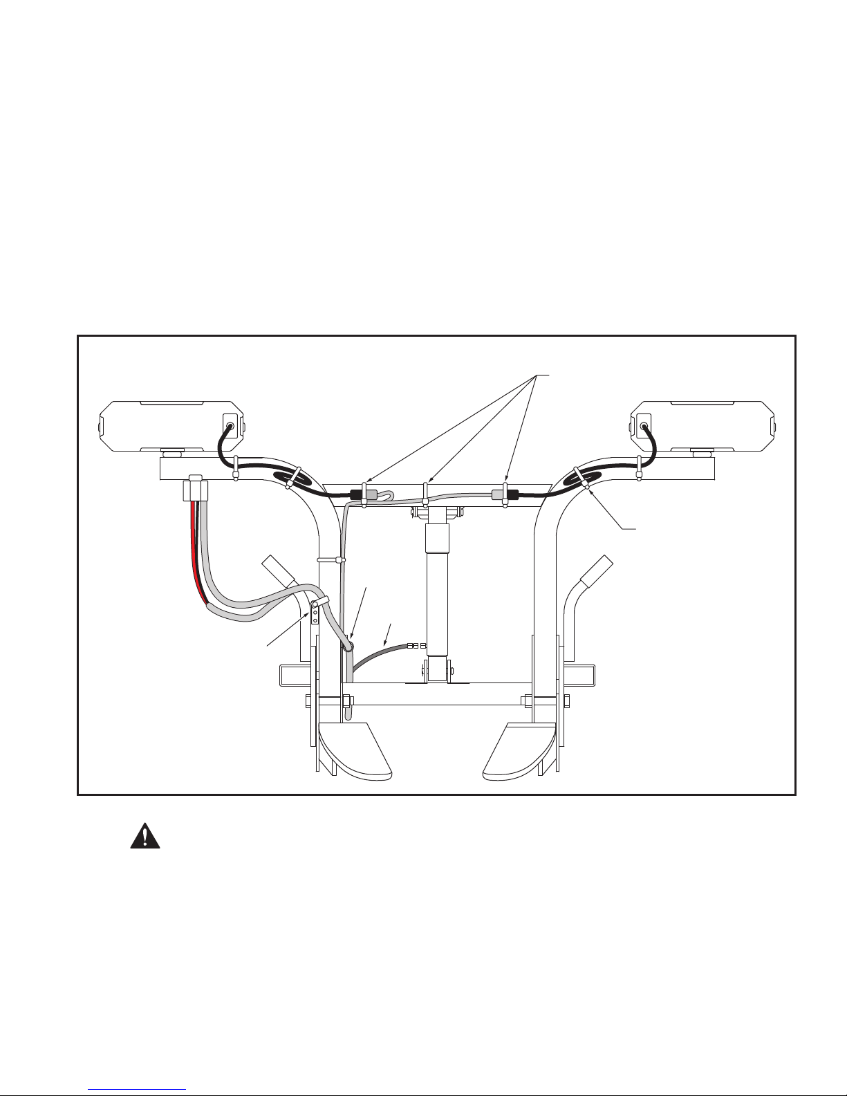
Routing of Harness and location of each Harness Clip & Wire Tie is very
important so that it will 'ex' properly when the Plow is lowered or raised.
Failure to correctly route and secure Harness may result in severe damage.
D.) Plug the Plow Light Connectors into Harness and secure the connected Plugs to the Lift Frame.
Excess Cord from Lights can be secured with Tie-Wraps where shown. Figure 11.
Section 7. Harness Steps
A.) If Harness and Lift Cylinder Hose are not pre-wrapped together with Hose Wrapping, tie together
using (3) Wire Ties 4" apart starting at the A-Frame exit.
B.) Secure the Harness to the Lift Frame using supplied Harness Clips, Bolts, Nuts and Wire Ties.
C.) Attach Plow Harness to Lift Frame at Tab 'A' using supplied P-Clamp. Route Plow Harness in front
of Lift Frame Up Left tube (Driver’s side) and attach Harness to Tab 'B' using supplied P-Clamp.
Tab 'B' has 3 mounting holes to allow proper Harness reach for different height trucks. If the Plow is
assembled in the bottom set of Side Plate mounting holes, use the bottom hole in Tab 'B'.
See Figures 11 & 12.
17 of 25
Home-Pro 3000 Assembly Instructions
CAUTION
Connect Headlights
to Harness then secure
connected Plugs with Cable-Ties
Loop and secure
excess Headlight
Cable with Cable-Ties
Tab 'B'
with Clamp
Tab 'A'
with Clamp
Lift Hose
Figure 11. Secure Harness to Lift Frame

Home-Pro 3000 Assembly Instructions
18 of 25
Figure 12. Secure Harness to Lift Frame
After securing Harness, with Main Plug stored in Plug Storage Holder, it is important
to move Driver's Side Latch Hook through its cycle of motion by hand to ensure
clearance between Harness and any moving parts. Failure to properly secure
Harness could result in severe damage to the Harness.
CAUTION
Harness Clip
on Tab 'A'
Front Left (Driver's Side) of Lift Frame
To Lift Cylinder
Up to Lights
1/4" Bolt & Lock Nut
1/4" Bolt & Lock Nut
Harness Clips
Harness Clip
on Tab 'B'
Harness Routes behind
Home-Pro 3000 Assembly Instructions
19 of 25
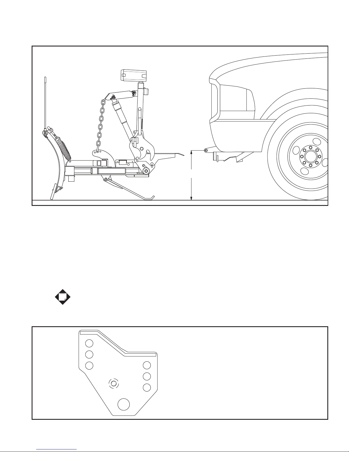
Figure 13. Determine X Height for Correct Side Plate Mounting Holes
Section 8. X Height Procedure
A.) Install Mount Kit on vehicle referring to Mount Kit installation procedure. Wire vehicle referring to
Page 22 for detailed Harness & Control System installation information.
B.) With vehicle parked on level ground and properly ballasted for snow plow use, measure the distance
from the ground up to the centerline of the Latch Bar on the Receiver as shown.
C.) Once 'X' dimension is measured, use the Application Chart below to determine which hole locations
to use when attaching the Lift Frame to the Side Plates.
This is a general guideline to help make the assembly process easier.
Due to great variations in suspension, tires, age of the vehicle, etc. it may be
necessary to change the Side Plate positions after Plow is attached to the vehicle.
Figure 14. Select Appropriate Side Plate Mounting Holes
X
Insert Spring End
into Keeper
Top
Center
Bottom Top
Center
Bottom
If X is 16-3/4" and above use Top Holes
If X is between 15-3/4" to 16-1/2" use Center Holes
If X is below 15-1/2" use Bottom Holes
NOTE

Home-Pro 3000 Assembly Instructions
20 of 25
Vehicle to Plow Initial Setup
Once Vehicle Mount Kit and Harness installations are complete, raise the Plow to the same level as the
Mount Kit Receiver. To accomplish this, drive truck close to Plow and attach the Harness Plug. Put 'In-
Cab' Control System into the 'oat' position and raise the Plow using the A-Frame Jack Switch to align the
rear of the Lift Frame with the Mount Kit Receiver. If necessary, readjust the Side Plate positions.
Jack Adjustment Procedure
With the Lift Cylinder & Jack fully retracted, top off the Pump Reservoir. It may be necessary to run the
Jack for 10 cycles as a break-in period. During the break-in period, check that the Jack retracts fully
against the Pan of the A-Frame. If the Jack Leg doesn’t fully retract, remove the A-Frame Cover and
manually adjust the tension on the Jack Leg Return Spring using a 1-1/8" open end wrench. The Jack
Return Spring is located forward of the Pump in the A-Frame Pump cavity. See Figure 15 below.
A 3/4" Hex Nut holds the tension on the Spring. If more tension is required, tighten the Hex Nut against the
Spring. When adjusting the Spring tension, use full turn increments and test the function of the Jack Leg after
each turn of the Hex Nut. Do not over tighten the Return Spring.
Figure 15. Jack Spring Adjustment
A-Frame with Cover removed
Jack Switch
3/4" Hex Nut to adjust Jack Spring
This manual suits for next models
2
Table of contents


