Safety 5
MAN1369
(10/31/2023)
TRAINING
■This machine is capable of amputating hands
and feet and throwing objects. Failure to ob-
serve the following safety instructions could
result in serious injury or death.
■Safety instructions are important! Read all
attachment and power unit manuals; follow
all safety rules and safety decal information.
(Replacement manuals and safety decals are
available from your dealer. To locate your
nearest dealer, check the Dealer Locator at
www.WoodsEquipment.com, or in the United
States and Canada call 1-800-319-6637.) Failure
to follow instructions or safety rules can result
in serious injury or death.
■If you do not understand any part of this manual
and need assistance, see your dealer.
■Know your controls and how to stop engine and
attachment quickly in an emergency.
■Operators must be responsible, trained, familiar
with the instructions and be physically capa-
ble of the safe operation of the equipment, its
attachments, and all controls. Do not allow any-
one to operate this equipment without proper
instructions.
■Keep hands and body away from pressurized
lines. Use paper or cardboard, not hands or
other body parts to check for leaks. Wear safe-
ty goggles. Hydraulic uid under pressure can
easily penetrate skin and will cause serious in-
jury or death.
■Make sure that all operating and service person-
nel know that if hydraulic uid penetrates skin,
it must be surgically removed as soon as possi-
ble by a doctor familiar with this form of injury
or gangrene, serious injury, or death will result.
CONTACT A PHYSICIAN IMMEDIATELY IF FLUID
ENTERS SKIN OR EYES. DO NOT DELAY.
■Never allow children or untrained persons to op-
erate equipment.
PREPARATION
■Check that all hardware is properly installed.
Always tighten to Bolt Torque Chart specica-
tions unless instructed otherwise in this manual.
■Air in hydraulic systems can cause erratic opera-
tion and allows loads or equipment components
to drop unexpectedly. When connecting equip-
ment or hoses or performing any hydraulic
maintenance, purge any air in hydraulic sys-
tem by operating all hydraulic functions several
times. Do this before putting into service or al-
lowing anyone to approach the equipment.
■Route hydraulic hoses carefully to prevent dam-
age. Hoses must not be twisted, bent sharply,
kinked, frayed, pinched, or come into contact
with any moving parts. Operate moveable com-
ponents through full operational range to
check clearances. Replace any damaged hose
immediately.
■ Make sure all hydraulic hoses, ttings, and
valves are in good condition and not leaking
before starting power unit or using equipment.
Check and route hoses carefully to prevent
damage. Hoses must not be twisted, bent sharp-
ly, kinked, frayed, pinched, or come into contact
with any moving parts. Operate moveable com-
ponents through full operational range to
check clearances. Replace any damaged hoses
immediately.
■Always wear relatively tight and belted clothing
to avoid getting caught in moving parts. Wear
sturdy, rough-soled work shoes and protec-
tive equipment for eyes, hair, hands, hearing,
and head; and respirator or lter mask where
appropriate.
■Power unit must be equipped with Roll Over
Protection System (ROPS) or ROPS cab and
seat belt. Keep seat belt securely fastened.
Falling off power unit can result in death from
being run over or crushed. Keep foldable ROPS
system in “locked up” position at all times.
■Make sure attachment is properly secured, ad-
justed, and in good operating condition.
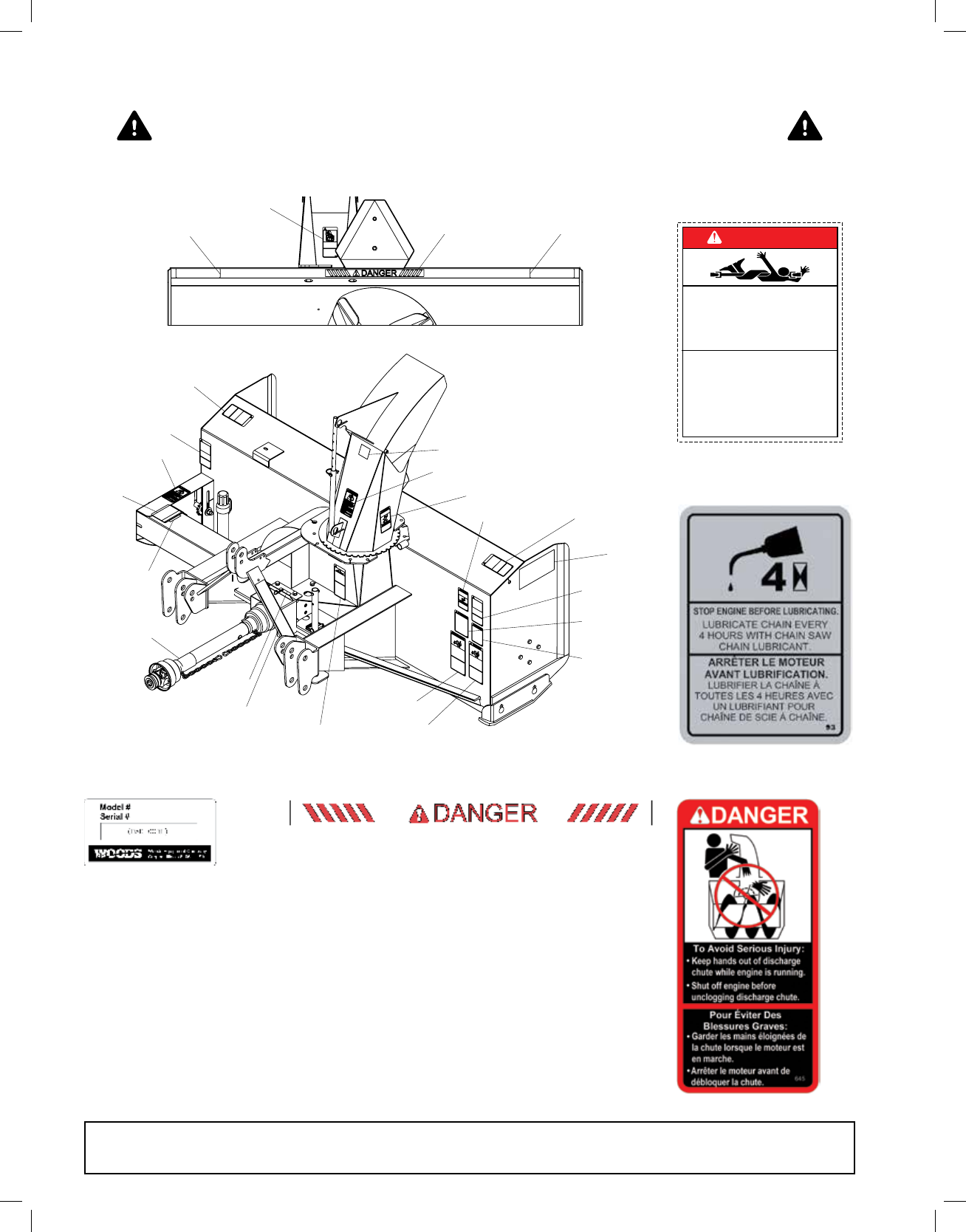
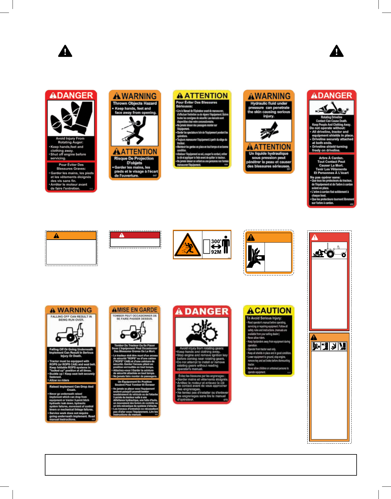
■Make sure all safety decals are installed.
Replace if damaged. (See Safety Decals section
for location.)
■Make sure shields and guards are proper-
ly installed and in good condition. Replace if
damaged.
Safety is a primary concern in the design and man-
ufacture of our products. Unfortunately, our efforts
to provide safe equipment can be wiped out by an
operator’s single careless act.
In addition to the design and conguration of
equipment, hazard control and accident preven-
tion are dependent upon the awareness, concern,
judgement, and proper training of personnel in-
volved in the operation, transport, maintenance,
and storage of equipment.
It has been said, “The best safety device is an in-
formed, careful operator.” We ask you to be that
kind of operator.
SAFETY RULES
ATTENTION! BECOME ALERT! YOUR SAFETY IS INVOLVED!
MAN1369_2023-10.indd 5MAN1369_2023-10.indd 5 11/1/23 4:20 PM11/1/23 4:20 PM