SNT SPIDER AUTONOMOUS 2.0 User manual

SPIDER
AUTONOMOUS
2.0
operation manual

SPIDER
AUTONOMOUS
2.0
The mower with
precision navigation
REV. 1_2023/06/05
operation manual

Table of contents
1 LIST OF ABBREVIATIONS ....................................................... 9
2 INTRODUCTION .......................................................................... 11
2.1 Important .................................................................................... 11
2.2 Use of the Machine ................................................................... 13
2.3 Prohibited Use ........................................................................... 14
2.4 Product Identification .............................................................. 15
2.5 Guidelines for the Disposal of Scrap Products .................. 16
3 SAFETY INSTRUCTIONS ....................................................... 17
3.1 Safety Instructions .................................................................... 17
3.2 Safety Markings ........................................................................ 23
4 SPECIFICATION ......................................................................... 25
4.1 Specification ............................................................................. 25
4.2 Noise Emission ......................................................................... 27
4.3 Declaration of Conformity ...................................................... 27
5 SAFETY MARKINGS ................................................................ 29
5.1 Service Position ....................................................................... 32
5.2 Recommended Working Procedures .................................... 33

6 CONTROLS AND ACCESSORIES .................................... 35
6.1 Remote Control SMAUT RCT01 ............................................. 35
6.1.1 RCT01 Controls ............................................................ 36
6.1.2 Display ........................................................................... 38
6.2 GNSS RTK Correction Station SMAUT CST01 .................... 39
6.2.1 CST01 Start-Up Procedure .......................................... 41
6.3 Multiple Charger SMAUT CHR01 ........................................... 43
6.4 Controls on the Mower ............................................................ 44
7 SIGNALING OF
ELECTRONIC COMPONENTS ............................................ 45
8 SAFETY SYSTEMS .................................................................... 49
8.1 Safety Systems ......................................................................... 49
8.2 Safety Bumpers ........................................................................ 53
9 MACHINE PREPARATION ..................................................... 55
9.1 Delivery of the Machine to the User ..................................... 55
9.2 Hydraulic Pump By-Pass ......................................................... 56
9.3 Checking the Oil Level in the Engine ................................... 57
9.4 Checking the Fluid Level in the Hydraulic System ............ 58
9.5 Accumulator Preparation ........................................................ 59
9.6 Fuel Tank ................................................................................... 60
9.7 Preparation of the Remote Control SMAUT RCT01 ........... 61
9.8 Recharging the Battery of the Remote Control
SMAUT RCT01 ........................................................................... 61
9.9 Preparation of GNSS RTK Correction Station
SMAUT CST01 ........................................................................... 62
9.10 Recharging the Battery of the GNSS RTK
Correction Station SMAUT CST01 ........................................ 62
10 OPERATION PROCEDURES ................................................ 63
10.1 Transport of the Mower ........................................................... 63
10.2 Machine Preparation and Engine Start-Up .......................... 64
10.3 Switching Off the Engine ........................................................ 65
10.4 Emergency Machine Shutdown ............................................. 66
10.5 Switching On the Mowing Deck ............................................. 67
10.6 Switching Off the Mowing Deck ............................................ 68
10.7 Setting the Mowing Height ..................................................... 69
10.8 Machine Travel .......................................................................... 70
10.9 Machine Travel Speed ............................................................. 71
10.10 Skid Steering ............................................................................ 72
10.11 SA 2.0 Driving Modes and Additional Information
for Operational Procedures .................................................... 73
10.11.1 Manual Mode ................................................................ 73
10.11.2 Correction Data ............................................................ 73
10.11.3 Autonomous Mode ........................................................ 74
10.11.4 Perimeter Mode ............................................................ 75
10.12 Driving on Slope ....................................................................... 78
10.13 Stopping the Mower on Slope ............................................... 80
11 APP MY.SPIDERNEWTECH.COM ..................................... 81
11.1 Login ........................................................................................... 81
11.2 App Design ................................................................................ 82
11.3 Creating a Job .......................................................................... 85
12 MAINTENANCE ........................................................................... 87
12.1 Mower Maintenance Plan ........................................................ 87
12.2 Engine Maintenance Plan ....................................................... 90
12.3 Engine Maintenance ................................................................ 92
12.4 Engine Oil Change ................................................................... 93
12.5 Cleaning the Fuel Tank ........................................................... 94
12.6 Hydraulic Drive Maintenance ................................................. 95
12.7 Checking and Topping Up the Hydraulic Fluid ................... 96
12.8 Adjustment of the Neutral Position
of the Travel Servomotor ........................................................ 96
12.9 V-Belts of the Mowing Deck Drive ......................................... 97
12.10 Wheels Geometry Adjustment ............................................... 98
12.11 Chain Case ................................................................................ 99

9
1LIST OF
ABBREVIATIONS
A SI unit of electric current — Ampere
Ah Ampere-hour
bar Metric unit of pressure
BT Bluetooth
CO Carbon monoxide
CZEPOS Provides users of global navigation satellite systems the
correction data for accurate positioning on the territory of
theCzech Republic
dB Decibel — unit for measuring sound intensity level
DGNSS Differential Global Navigation Satellite System
GPS Global Positioning System
GSM Global System for Mobile Communications
HP Unit of measurement of power — horsepower
kg kilogram
km/h Speed kilometer per hour
kPa Pascal is a unit of measurement of pressure.
1 000 Pa (kilopascal)
CST GNSS RTK Correction Station
kW SI unit of measurement of power — 1000 watts (kilowatt)
LCD Liquid crystal display
LED Light emitting diode
Li-Ion Lithium-Ion
LTE Technology for high-speed data transmission in mobile networks
MHz SI unit of measurement of frequency—1 000 000 Hz (megahertz)
mm/cm Millimeter/Centimeter
Nm Unit of measurement of torque — Newton meter
PC Computer
RC Remote control
List of Abbreviations
1
abbreviation English meaning
12.12 Maintenance of Eletrical Circuits, Equipment
and Navigation Components ............................................... 100
12.13 Adjusting Blade Deceleration .............................................. 101
12.14 Chains ...................................................................................... 102
12.15 Fuses ........................................................................................ 103
12.16 Mowing Blades ........................................................................ 104
12.17 Changing the Wheel ............................................................... 106
12.18 Tyre Pressure .......................................................................... 106
12.19 Mowing Height Adjustment Mechanism ............................. 107
12.20 Lubrication .............................................................................. 107
12.21 Cleaning the Machine ............................................................ 108
12.22 Cleaning the Mowing Deck ................................................... 108
12.23 Torque Chart ........................................................................... 109
12.24 Viscosity of Engine Oils ........................................................ 109
12.25 Technical Plate ........................................................................ 110
12.26 Tools .......................................................................................... 111
12.27 Auxiliary Drive Brake .............................................................. 112
12.28 Accumulator Maintenance ..................................................... 114
13 FAULTS AND EXCEPTIONAL OPERATING
CONDITIONS .............................................................................. 117
14 POST-SEASON MAINTENANCE ..................................... 123
15 SUPPORT FOR
SPIDER AUTONOMOUS 2.0 ............................................. 125
15.1 Warranty Conditions .............................................................. 125
15.2 Maintenance Support ............................................................ 126

1110
2INTRODUCTION
REC Recording
RPM Revolutions per minute
RTCM Real-time correction message
RTK DATA Machine receives correction data
RTK FIX The machine knows its exact position
s SI unit of measurement of time — second
SA Spider Autonomous
SIM An identification card used to identify a subscriber on a mobile
network
SOS Emergency situation
TEST Testing
UHF Ultra-high frequency
URL Web address
V Volt — voltage
Introduction
2
2.1 IMPORTANT
Abbreviation English meaning
This machine is intended for normal grass cutting use only. Any other use is
contrary to the intended use of the machine. Strict compliance to the conditions
of use, maintenance and repair as prescribed by the manufacturer is must to
the proper operation of the machine.
Before using the machine, EVERY operator MUST attend practical training in
mower operation, read this manual thoroughly and become properly familiar
with all safety instructions, controlling the machine and maintenance instruc-
tions. The mower may be operated with other attachments intended for the
mower, but the instructions given for each attachment must be followed.
It is essential to comply with all regulations relating to accident prevention, as
well as all other generally accepted regulations relating to occupational safety
and health and all applicable traffic rules and regulations.
The manufacturer disclaims responsibility for any modifications or changes
made to the product that are not made and approved by the manufacturer.
Furthermore, the manufacturer disclaims liability in the event of non-com-
pliance with the user manual, as well as the consequences in the form of
damage to property or health of the operator or other persons that may
result.
This machine places demands on the operator both in terms
of operation and maintenance.
This USER MANUAL is a part of the machine. Always
keep the manual available with the machine and, in case
of transfer to another owner, pass on the manual as well.

1312
2INTRODUCTION
This user manual contains instructions for safe operations in various places. If
this instruction is included in the general text, it is highlighted by the following
WARNING symbol:
2.2 USE OF THE MACHINE
The machine is designed for mowing grassland on flat or extremely sloping
terrain, with the option of autonomous or manual control. Any other use is
contrary to the established method of use. The maximum slope inclination on
which the machine may be used depends on the actual condition of the mown
area and the mowing method.
The SPIDER AUTONOMOUS 2.0 is a product designed for mulching grass in
unmaintained or only occasionally mown areas. The mower is operated by a
single person via a remote control, which allows manual or autonomous control
of the machine along pre-calculated routes in a given working area.
This machine may only be operated, repaired and maintained by authorized re-
sponsible person over 18 years of age, who is physically and mentally capable
of doing so. Who has learnt operational procedures for the correct and safe
use and maintenance of the machine by means of this manual, and who has
familiarized himself with the applicable regulations and principles of occupa-
tional safety and health when working with the SPIDER AUTONOMOUS2.0
motorized mulching lawn mower.
Dry conditions
Cross-slope mowing (manually and autonomously): Maximum slope is 35°
Mowing up and down the slope (manually and autonomously): Maximum slope is 36°
Cross-cutting on the slope with the machine
positioned diagonally (manually only): Maximum slope is 41°
Wet conditions
For all surfaces and applications with manual or
autonomous mode: Maximum slope is 20°
MAX 35°MAX 36°MAX 41°MAX 20°
It warns of the very likely risk of serious injury
or danger to life if the appropriate instructions are
not followed.
It is also used:
It provides useful information.
Links to the service video on the manufacturer’s website.

1514
2INTRODUCTION
When driving on a slope, the operator must carefully observe and evaluate the
movements of the mower and the characteristics of the terrain, especially the
current grip of the wheels on the ground. Pay attention to climatic conditions.
The slope accessibility of the mower changes quickly on dry or wet grass. Soil
characteristics also play a significant role. Adhesion to the ground will be much
greater on dry slopes and on hard ground.
2.3 PROHIBITED USE
The mower must not be used for any purpose other than that for which it
is intended and which is described in chapter 2.2 Use of the Machine.
The mower must not be used on surfaces that are contaminated with glass,
stones, iron or other undesirable objects that can be ejected by the rotating
blade or that can damage the mower when cutting.
The mower must not be used on slopes exceeding 20° in wet, humid or fog-
gy conditions where slope accessibility and mower stability are adversely
affected by adhesion to the ground, regardless of the type of area being
mowed.
The mower must not be used in manual mode if people, children or animals
are within 3 meters of the machine/mowing area.
The mower must not be operated in autonomous mode unless the fol-
lowing conditions are met: working in an enclosed, fenced area without
the presence of other persons or working in an area marked by safety
features (safety signs indicating that the machines are operating in
autonomous mode or mobile fencing demarcating the working area).
The mower must not be started in autonomous mode unless the oper-
ator has visual contact with the machine and the surrounding area is
secured.
Under no circumstances should the mower be used unless you
have thoroughly familiarized yourself with the terrain beforehand, in
particular the presence of undesirable uneven ground, protrusions,
stumps, areas of low load-bearing capacity, swamps, depressions, etc.
The mower must not be used on slopes with a greater inclination than that
is specified in section 2.2 Use of the Machine.
The mower must not be used as a towing or transport vehicle.
It is strictly forbidden to drive the mower on public roads.
It is strictly forbidden to increase the maximum speed or power of the
engine beyond the limits specified by the manufacturer, and to make any
other interventions in the design of the machine, the engine settings, or the
settings of the control unit and navigation components. The manufacturer
accepts no liability for damage or injury resulting from such interventions
and modifications.
It is strictly forbidden to use the machine after consuming alcohol or drugs
affecting perception or other psychotropic or hallucinogenic substances.
It is strictly forbidden to drive the mower into piles of sand, gravel and
similar materials, stumps, stones, building elements or other obstacles that
may cause the machine to become unstable.
It is strictly forbidden to use the machine in low visibility (twilight, fog, heavy
rain, etc.).
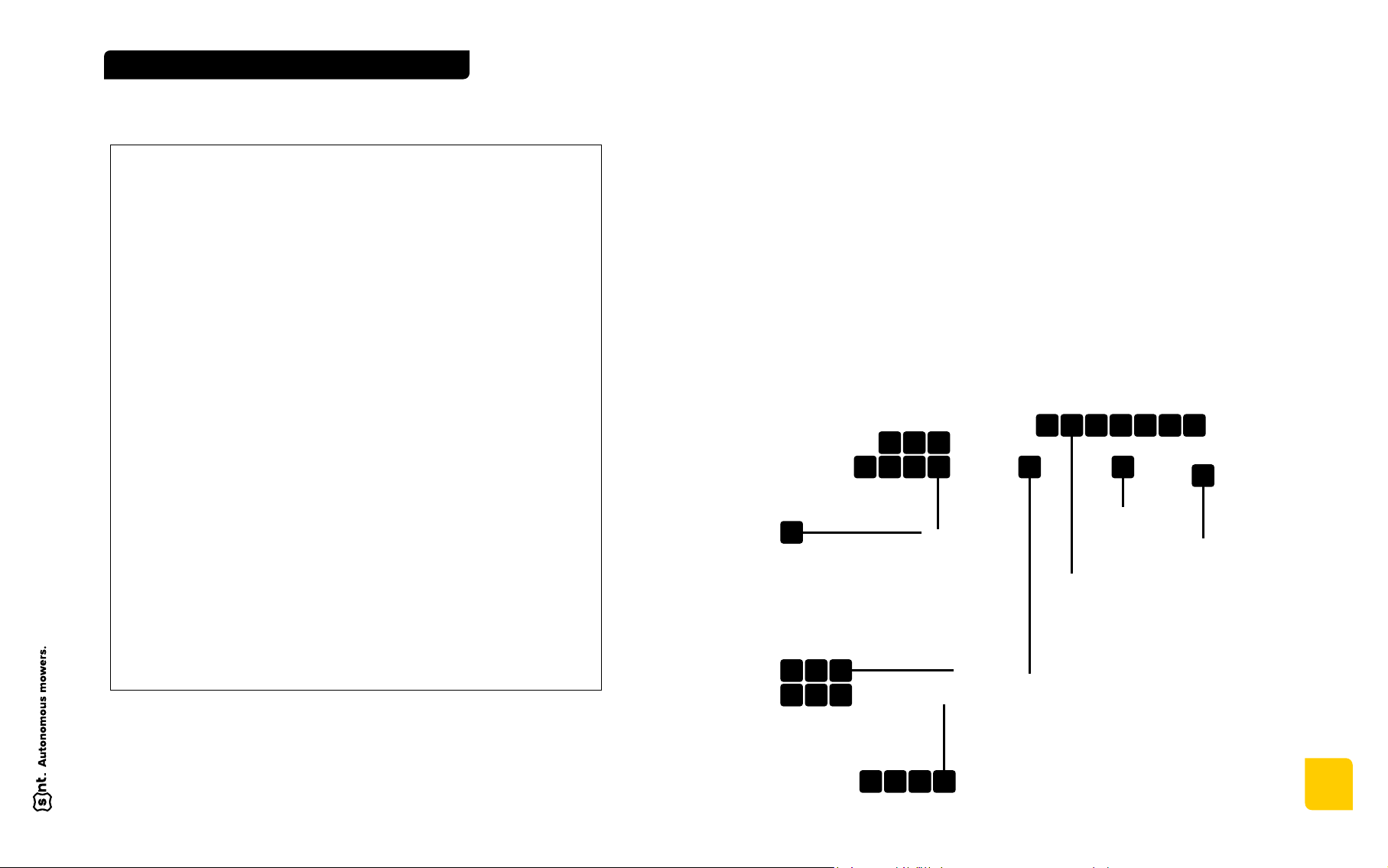
2.4 PRODUCT IDENTIFICATION
The machine can be identified by the serial number on the mower’s factory
label, which is located at the front of the machine near the exhaust.
The engine manufacturer has also placed its own factory label on the
combustion engine.
Type
Engine: Kawasaki FS 730V EFI
Hydrostatic system:
Electronic system:
Tires:
Lubrication:
AUTONOMOUS 2.0
Oil 10W40 / API SG
Quantity 2,1 l
Oil HV 68
Accumulator 12V/18Ah FBTX20L
Type 16 x 6,50 - 8
Pressure max. 300kPa / 43 PSI
Chains INTERFLON FIN LUBE TF
INTERFLON FIN LUBE TF
Sliding surfaces
Fuses 5A/7,5A/10A/20A/40A
Quantity 8,5 l
Spark plugs NGK BPR4ES
Fuel Unleaded petrol
engine
factory
label
location
mower
factory
label
location
mower factory
label
1716
SAFETY
INSTRUCTIONS
3
2.5 GUIDELINES FOR THE DISPOSAL
OF SCRAP PRODUCTS
If you consider that this machine has no longer any functional value and requires
disposal, then you should take the following steps.
These guidelines should be applied in accordance with applicable health,
safety and environmental legislation and with the assistance of approved local
waste disposal and recycling facilities.
Use the appropriate tools and
personal protective equipment
and follow the technical instruc-
tions applicable to the machine.
Remove and store properly:
1. Batteries
2. Fuel residues
3. Oils
Disassemble the machine struc-
ture in accordance with the
instructions where possible. Par-
ticular attention should be paid
to working with “hidden energy”
inside the machine’s pressure
elements or tension springs.
Any component that could still
serve as a used part or that can
be repaired should be separated
and returned to the appropriate
centre.
Other used parts should be sep-
arated into material groups and
taken for disposal and recycling
in accordance with available facil-
ities. It is usual to separate them
into the following types:
•Steel
•Non-ferrous metals
—Aluminium
—Brass
—Copper
•Plastics
—Identifiable
Recyclable
Non-recyclable
— Unidentified
•Rubber
•Electrical and electronic
components
Items that cannot be economically
categorized by material should be
labeled as “General Waste”.
Do not burn the waste.
Finally, update the machinery records and mark the machine as scrapped.
Safety Instructions
3
3.1 SAFETY INSTRUCTIONS
Do not enter or interfere with the
machine if it is raised and not ad-
equately supported. The machine
should be supported at the points
marked with the hoist symbol.
Transport the machine on a crate
or trailer.
Carry out maintenance and tighten-
ing checks on bolted connections
at regular intervals. The first check
should take place after 10 hours
of operation. Pay attention to the
attachment of the mowing blades
and the proper tightening of the
bolts. Use a torque wrench and the
prescribed tightening torque, see
12.23.
Knife attachment hubs and bolts
must not show signs of damage or
wear. The bolts must be complete.
The knives must be undamaged,
evenly used and reasonably sharp.
Tighten the bolts to the prescribed
torque.
When moving the machine in man-
ual mode outside the working area,
always switch off the cutting blades
and set the maximum cutting
height. This will prevent damage to
the blades.
Keep the product clean after use.
Do not use gasoline or similar
petroleum products for cleaning.
This safety symbol indicates an important safety
message in this user manual.
If you see this symbol, always beware of possible
injury, read the following messages carefully
and inform other users.

1918
SAFETY
INSTRUCTIONS
3
Do not reach under the mowing
deck or under the engine covers
or into the gearbox with your hands
or feet.
If you are forced to reach under
the machine, wait until all rotating
parts have stopped. Watch out,
the blades are catching up! The
running time depends on the
condition and wear of the clutch.
Ensure that the clutch is regularly
serviced by a qualified workshop.
The EMERGENCY STOP button
must be in the OFF position before
intervention.
Wear sturdy, closed shoes and
work clothes when operating
the machine. Do not wear short
trousers, light footwear or loose
clothing, parts of which could be
caught by the mower.
It is strictly forbidden for the machine
operator to wear loose clothing.
Use a face shield to protect your
face.
Do not use the machine after
consuming alcohol or a drug that
affects perception or drugs.
Always make sure that the mowing
deck is switched off before starting
the engine.
When starting up the mowing deck,
stand well back from the machine
to protect yourself from objects
thrown accidentally and to be able
to stop the machine in time in case
of danger. Do not step into the
possible path of the mower.
When using the mower in manual
mode, make sure that you can
always see the machine clearly,
that it is within range of the remote
control and that you can recognize
and react to dangerous situations
in good time. Do not abuse the
maximum range of the remote
control.
When using the mower in autono-
mous mode, check the operating
status of the mower using the app
my.spidernewtech.com on a PC,
laptop, tablet or phone.
Observe all generally applicable
safety regulations when using the
mower.
Only start working with the mower
if the machine has not been dam-
aged by previous operation.
Do not interfere with engine ad-
justments, especially the speed
governor, and do not modify the
exhaust.
Do not operate the mower if you
have less than 30% fuel in the tank.
Do not move the mower by drag-
ging it with the towing device.
The machine is intended for opera-
tors over 18 years of age who have
been trained and familiarized with
the machine and the instructions
for use. The remote control (here-
inafter referred to as “RC”) and the
correction station (hereinafter re-
ferred to as “CST”) are considered
as part of the machine.
The user manual must be kept in
a place that is permanently acces-
sible to the machine operator and
must be available to the operator at
all times.
Do not allow children or unauthor-
ized persons to use the product.
Before starting the machine, you
must be familiar with all the sym-
bols on the controls and indicators
on the mower, RC and CST.
Pay particular attention to stopping
and switching off the engine and
to emergency shutdown of the
machine.
Before using the mower on a slope,
first check your ability to operate
the mower on a sufficiently clear
and spacious area. Learn how to
perfectly control the movement on
the surface, cutting bushes, trees
and other terrain features and
obstacles.
When operating and moving the
mower on a slope in manual mode,
always keep the engine speed set
to maximum. When stopping and
stopping the machine on a slope,
turn the wheels perpendicular to
the slope.
When using or transporting the
mower in manual mode, the opera-
tor must always have the mower in
his/her field of vision. The maximum
safe distance between the operator
and the mower is 50 meters.
When using the mower, please
strictly observe the safety regula-
tions in this manual, while respect-
ing local rules and regulations for
noise-emitting machines, espe-
cially when using in hospitals, spa
facilities and other sensitive areas.
The operator must pay particular
attention to the area into which
mulch grass can be ejected by
the rotation of the blade. This
area must not be entered by the
operator, other persons, children
or animals. Particular attention
must be paid to protection against
possible unwanted particle drift,
especially when mowing uneven
surfaces where the mowing deck
may be deflected (by lifting one
side of the machine) when crossing
or climbing over terrain edges.
The machine operator is respon-
sible for any damage caused to
third parties by the machine. The
mower may be used to work on
slopes with the gradients specified
in chapter 2.2 Use of the Machine.
Before you start mowing, remove
all stones, pieces of wood, glass,
wires, bones, branches and other
foreign objects that could be
crushed or damage the mower.
When using the mower, avoid ob-
stacles, do not climb on elevated
obstacles (stones, stumps, parts of
buildings), do not drive near cliffs,
ravines, unpaved ground or where
there is a risk of the machine falling
or tipping over.
Pay attention to the power lines
when working. Especially when
in manual mode, the connection
to the RC may be disturbed. In
this case, the mower immediately
switches off the combustion engine
and stops all movements.
If you use the machine on busy
roads, make sure that the mower
does not endanger people walking
or driving by or their property by

2120
SAFETY
INSTRUCTIONS
3
dropping objects. Choose an ap-
propriate working procedure (see
Chapter 10 Operation procedures).
The machine operator is responsi-
ble for the safety of persons enter-
ing and staying in the working area
of the machine. If these persons
enter the work area, stop work.
The transport of persons, animals
or loads on the mower is prohibited.
Do not place any objects or tools
on the mower.
When using the mower — especially
if it is windy — orient the operator’s
position so that exhaust fumes,
dust or mulch grass are not blown
onto the operator.
In dusty environments, stop work
and clean the machine and cooling
surfaces to prevent overheating
during operation. If necessary,
clean the machine and its cool-
ing surface several times during
operation. The dust layer must not
exceed 1 mm.
Refuel only when the machine is
switched off and the fuel tank is
cool, preferably before starting
work. Keep at least 30 % of the
fuel in the tank of the mower. If you
need to refuel while working, do not
refuel in a hot tank or with a hot
engine. Allow the machine to cool
down.
Before refueling, press the EMER-
GENCY STOP button on the central
control panel of the mower to the
OFF position.
Do not refuel while the machine
engine is running.
Do not start the engine if there is
spilled fuel, open containers of fuel
or other combustibles or flammable
gases in the immediate vicinity of
the mower.
Do not refuel near an open flame.
Do not expose/exhibit the machine
near open flames or sources that
emit heat.
Do not touch parts of the machine
that are getting hot while the ma-
chine is running or immediately
after it has been stopped. This
includes in particular the engine
exhaust, metal parts of the hydrau-
lic drive and metal parts of the
combustion engine.
Do not touch the high-voltage wire
leading to the spark plug while the
machine is running.
After starting the engine, check the
emergency shutdown function on
the RC. Press the SOS/TEST but-
ton (for Autonomous and Perimeter
mode) or the main switch/EMER-
GENCY STOP on the RC (for Manual
mode) to verify its functionality. The
machine must flash the LED strips
on the machine’s perimeter red
(rotation) in response to pressing
the SOS/TEST button or the main
switch/EMERGENCY STOP. This
step is a prerequisite for Manual
mode, Autonomous mode and Pe-
rimeter mode. Check this function
at least 1 time during the shift, but
always if you move the mower to a
new mulching area.
Before starting work, test the func-
tion of the emergency stop safety
features on the mower.
Never leave the machine unattend-
ed with the engine running.
When the machine engine is run-
ning, do not put down the RC and
do not touch or move any parts of
the machine.
When leaving the machine for a
short period of time, always switch
off the machine by pressing the red
EMERGENCY STOP button on the
central control panel of the mower
to the OFF position and then re-
moving the key to secure it against
starting. Do not leave the RC with
the mower, but in another properly
secured location that is inaccessi-
ble to unauthorized persons.
Only start the cutting blades just
before starting to cut.
Switch off the mowing deck, switch
off the engine and press the red
EMERGENCY STOP button on the
central control panel of the mower
to the OFF position and then
remove the key whenever:
— you clean the machine
— removing debris on the cutting
deck (grass or other objects).
— you hit a foreign object and need
to identify possible damage or
repair it
— the machine is vibrating unnat-
urally strongly and the cause of
the vibration needs to be deter-
mined
— repairing the engine or other
parts of the mower (also discon-
nect the cables from the spark
plugs).
When working, avoid brush,
concrete bases, bollards, stumps,
random stones, curbs in flower
beds and walkways, which must
not come into contact with the
blade. There is a risk of damage.
Do not drive the mower into piles of
sand, gravel and similar materials,
stumps, stones. Pay close attention
to isolated old stumps or stones or
building elements that may cause
instability of the machine.
It is strictly forbidden to drive on
these elements.
Only operate the machine in day-
light or in sufficiently good artificial
light.
Do not use the machine in low visi-
bility (twilight, fog, heavy rain, etc.).
Do not leave the machine running
in enclosed areas. Exhaust fumes
contain CO, are harmful to human
health and can cause death.
Start the engine or leave it running
only in the open. If the engine
of the machine is started or left
running in an enclosed area, the
exhaust gases must: be exhausted
by extending the exhaust pipe of
the machine outside the enclosed
area, sufficient ventilation and fresh
air supply must be provided to
prevent the build-up of CO.
Allow the mower engine and hy-
draulic drive to cool down properly
before putting it in an enclosed
area.
Regularly remove combustible sub-
stances (dry grass, leaves) from
the exhaust, engine, accumulator,
mower belts and clutch.
2322
SAFETY
INSTRUCTIONS
3
In manual mode, always operate
the machine from a position where
you have a perfect view of the en-
tire work area and the mower and
are not endangered.
When working in manual mode,
change the work position as re-
quired so that you always have a
perfect view of the mower.
Never enter the area under or
directly above the mower when it is
working on a slope.
In manual mode, choose an oper-
ator’s position at a sufficient dis-
tance from the mower (maximum
50 meters) to be protected against
foreign objects accidentally flying
away from the mower.
In manual mode, do not operate
the mower unless you can see it
(behind terrain obstacles, around
the corner of a building, hidden in
the grass, etc.)
The CST must be placed in a
specific location determined after
measurement by the manufacturer.
It must be secured against change
of position, damage and misuse by
an unauthorized person. The man-
ufacturer, the mower distributor or
the geodetic service accepts no
liability for incorrect transmission
of correction data caused by incor-
rect positioning or use of the CST.
Before starting the mower in
Autonomous mode, the operator
must check that the route has
been uploaded correctly in the app
my.spidernewtech.com.
Before starting the Autonomous
Mode, the operator must secure
the machine surroundings and the
entire work area.
Before starting in Autonomous
mode, the operator must have the
mowing deck control lever in the off
position.
Before starting in Autonomous
mode, the machine must be
calibrated, must know its exact po-
sition “RTK FIX” and must receive
correction data “RTK DATA” (see
chapter 10 Operation procedures).
Calibration of the machine must
be carried out without the mowing
deck switched on and the machine
must know its exact “RTK FIX”
position.
If the mower stops during Auton-
omous Mode, it is the operator’s
obligation to check the condition
of the machine before restarting it
in Autonomous Mode.
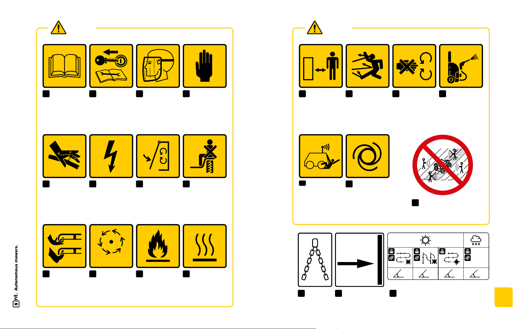
3.2 SAFETY MARKINGS
Check the condition of the safety markings before putting the mower into
operation. If the decals are missing or damaged, contact your dealer to
have them reinstated on the machine. Familiarize yourself thoroughly with
them. It is compulsory to place the stickers on the machine.
Do not remove or damage the safety markings on the machine.
Do not remove any covers or safety features from the machine. They are
there for your protection.
Do not use the machine with damaged or missing protective devices and
covers.
Always keep the machine and its accessories clean and in good working
order.
It is not permissible to carry out changes and interventions on the machine
that are not approved by the manufacturer. Any change made to the ma-
chine may lead to a dangerous situation and injury. If these instructions
are not followed, the manufacturer is not liable for the machine and the
warranty may be void.
Always use a machine equipped with all cover elements.
It is forbidden to use the machine without a properly fitted or damaged
rubber mulching cover with chains.

2524
SPECIFICATION
4
Specification
4
4.1 SPECIFICATION
The SPIDER AUTONOMOUS 2.0 is a self-propelled machine with four-wheel
drive, controlled by a remote control or driven autonomously using DGNSS
(a global navigation satellite system that provides real-time differential correc-
tions), inertial navigation and sensors. The unique way of steering the wheels
stands out for its high maneuverability both on flat ground and on slopes. The
base of the machine is a square rigid frame which is slidingly connected to
the sliding frame. The center of the sliding frame houses all the propulsion
components such as the internal combustion engine, the tandem hydraulic
fluid pump and two hydraulic motors, the control unit, as well as the dome and
antennae of the navigation components. At the bottom of the frame, on the
outside, are the tethers at the ends of which the four cutting blades are fixed.
An electromagnetic clutch is inserted between the main drive pulley and the
motor. The mowing deck is four-blade. The outlines of the circles describing the
cutting knives do not overlap. The casing protecting the mower deck extends
circumferentially beyond the path of the mower blades. The blades are fixed,
mounted between flanges and tightened by central bolts. The housing has a
recess on the input/output side where the material enters the machine. These
openings are protected by a metal-chain hinge and a rubber screen to prevent
unwanted parts from escaping. Above the rubber hinge, a steel barrier is fixed
on the outside to define a safe distance from the cutting blade. Travel is pro-
vided by four wheels mounted on the end portal gears. The wheels are driven
by two hydraulic drive motors with V-belts. Wheel turning is provided by an
electric motor. Steering is carried out by remote control with Bluetooth module
(hereinafter BT) or by transmitting on a specific UHF frequency.

2726
SPECIFICATION
4
parameter unit size/type/quantity
LENGTH × WIDTH × HEIGHT mm 1640 × 1430 × 920
SHOT mm 1230
CUTTING BLADE HEIGHT
(INFINITELY ADJUSTABLE) mm 70—120; 90—140
WEIGHT kg 385
TRAVEL SPEED km/h 0—8
MOWING EQUIPMENT four-legged, with fixed blades
LENGTH OF THE KNIFE mm 505
MOWING CLUTCH electromagnetic with friction brake
HYDRAULIC FLUID
PUMP
HYDRO-GEAR
TL-SGGV-EGGV-1XHX
PK-KNGG-6V1X-AXXX
HYDRO MOTOR DRIVE M+SHYDRAULIC MR 50CDRS/4
DRIVE SYSTEM 4 × 4
RUNNING WHEELS inch 16 × 6,5 with arrow pattern
ACCUMULATOR 12 V,18 Ah, gel
FUEL petrol — natural 95
FUEL TANK CONTENTS liter 16
ENGINE air-cooled 4-stroke twin-cylinder
Kawasaki FS730V EFI 25,5 HP
TABLE OF CONTENTS cm³ 726
POWER kW 19,0
ENGINE SPEED 1/min 3600
IGNITION Electronic
STARTER Electric
FREQUENCY RANGE OF
REMOTE CONTROL AND
CORRECTION STATION
MHz 430.000 – 470.000
4.2 NOISE EMISSION
The mower emits the following noise:
Sound pressure level LWA = 99,9 dB
Guaranteed Sound pressure level LWA = 101,0 dB
The measuring was carried out in conformity with ISO 3744.
Noise at the operator’s station (ear):
L = 81.0 dB (A) Leq — Measured in the distance of 3 m from the machine
according to EN 11 201.
2928
SAFETY
MARKINGS
5
Safety
Markings
5
Attention! This machine can be dangerous! Incorrect or careless use of
the machine can result in damage, serious injury or even death. The safety
warning signs explained in this chapter are located on the important places
on the machine and warns of possible dangers. For individual symbols
explain what the danger is. Understanding the meaning of these symbols
and these dangers is a prerequisite for safe use of the product.
22
20
21 19
9
1
5
13
2
7
10
4
8
22
1 9 13 14 10 216
1 9 13
14 10 216
4.3 DECLARATION OF CONFORMITY
ES/EU PROHLÁŠENÍ O SHODĚ (originál)
EC/EU declaration of conformity (the original)
Výrobce / Manufacturer: SNT- SPIDER NEW TECHNOLOGY s.r.o.
Adresa / Address:Froncova 476, Hostavice, 198 00 Praha 9
IČ / ID:17332273
Jméno a adresa osoby pověřené sestavením
technické dokumentace (podle 2006/42/ES, NV
č. 176/2008 Sb.) a jméno a adresa osoby, která
uchovává technickou dokumentaci (podle
2000/14/ES, NV č. 9/2002 Sb.)/
Name and address of the person authorised to
compile the technical file (ac
cording to
2006/42/EC) and
the name and address of the
person who keeps the technical documentation
(according to 2000/14 / EC, NV No. 9/2002
Coll.):
SNT- SPIDER NEW TECHNOLOGY s.r.o.,
Froncova 476, Hostavice, 198 00 Praha 9
Výrobek (stroj) – typ /
Product (Machine) – Type:
Sekačka spreciznímovládáním SPIDER Autonomous 2.0 typ 2SGS EFI
Mower with precision control SPIDER Autonomous 2.0 type 2SGS EFI
Výrobní číslo / Serial number:---
Popis / Description:
Dálkově řízený žací stroj s možností autonomního režimu, určenýpro
sečení
a mulčování travnatých porostů na běžném i svažitém terénu.
Remote-controlled mowerwith the option of autonomous mode,designed for
mowing and mulching grass on both normal and sloping terrain.
Prohlašujeme, že strojní zařízení splňuje
všechna příslušná ustanovení uvedených
směrnic (NV) /
We declare that the machinery fulfils all the
relevant provisions of the mentioned Directives
(Government Provisions):
Směrnice 2006/42/ES, NV č. 176/2008 Sb. /
Directive 2006/42/EC.
Směrnice 2014/30/EU, NV č. 117/2016 Sb. /
Directive 2014/30/EU.
Směrnice 2000/14/ES, NV č. 9/2002 Sb. /
Directive 2000/14/ES.
Harmonizované technické normy
a technické
normy použité k posouzení shody /
The harmonized technical standards and the
technical standards applied to the conformity
assessment:
ČSN EN ISO 12100, ČSN EN ISO 5395-1, ČSN EN ISO 5395-2,
ČSN EN ISO 18497, ČSN EN ISO 4413, ČSN EN ISO 13857,
ČSN EN ISO 14982:2009, ČSN EN ISO 11201, ČSN EN ISO 3744.
Osoby zúčastněné na posouzení shody/
Persons participating conformity assessment:
Notifikovaná osoba č. 1016/ Notified Body No. 1016.
Státní zkušebna strojů a.s., Třanovského 622/11, 163 04 Praha6–Řepy, ČR /
The Government Testing Laboratory of Machines, Joint-stock company.
Závěrečná zpráva č.:
42 060
Použitý postup posouzení shody/
Used conformityassessmentprocedure: Na základě směrnice 2000/14/ES, příloha VIII;
NV č. 9/2002 Sb., příloha č.7.
On the basis of Directive 2000/14/EC, Annex VIII.
Naměřená hladina akustického výkonu/
Measured sound power level:
L
WA
= 99,9 dB
Garantovaná hladina akustického výkonu/
Guaranteed sound power level:
L
WA,G
= 101 dB
Poznámka: Veškeré předpisy byly použity ve znění jejich změn a doplňků platných v době vydání tohoto prohlášení bez jejich citování.
Note: All regulationswere applied in wordingof lateramendmentsandmodificationsvalid at the time of thisdeclarationissue without anycitationof them.
Místo a datum vydání /
Place and date ofissue: Praha 16.5.2023
Osoba zmocněná k podpisu za výrobce /
Signed by the person entitled to deal in the name of producer:
Jméno / Ing. Vincenc Šopík
Name: Lubomír Dvořák MBA
Funkce / CEO
Grade: CEO
Podpis /
Signature:
3130
SAFETY
MARKINGS
5
MAX 35°MAX 36°MAX 41°MAX 20°
Before use please
read user manual
When the machine
is moving, keep
asafe distance
Use protective
work equipment;
eye protection
Attention, rotating
parts, danger of
dragging or shearing,
do not remove safety
cover when the
machine is running
Before starting
theoperation
close all protective
covers
Attention,
flammable
substance, fire
hazard
Attention,
when replacing
themowing blades use
hand protection
Mower mustnot
be cleaned
byhigh pressure
water
Prohibition of
transporting
persons on the
machine
Danger of burns,
hot parts
When performing
maintenance,
repairs and interventions
on the machine follow the
operation manual, remove
the key from the ignition
Attention, danger
of being hit by
anejected object, keep
asafe distance
Attention, electric
accumulator
Attention, rotating
parts after
shutdown are
running out
Attention,
equipment uses
hydraulic drive, risk
ofinjury by spurting
ofhydraulic fluid
A place
forhanging
thelifting lashings
Attention, danger
of injury of the
upper/lower limbs by
rotating knives
SERVICE POSITION
STOP
NO
113
5
20
Machine tilt direction
into service position
(see chapter 5.1)
21
Never move on the slope in
the area under the machine,
ordirectly above it
19
9
214
Danger of being
run over by an
autonomous or remotely
controlled machine,
secure the working area
of the machine
Attention, automatic
start of the mowing
deck during entry into
Autonomous mode
17 186
10
315
7
11
416
8
12
SAFETY
WARNING
SAFETY
WARNING
Maximum permissible slope inclination
with regard to the type of use and climatic
conditions (see chapter 2.2)
22

3332
SAFETY
MARKINGS
5
5.2 RECOMMENDED WORKING PROCEDURES
These pictograms provide basic information about working with the machine
in different terrain conditions with three different modes of machine operation.
It is always the operator’s responsibility to choose the most suitable working
method, especially with regard to safety. In any case, it is always necessary to
follow the safety instructions and other instructions given in this user manual.
These pictograms are located on the top cover of the machine.
RC MOWING GPS PERIMETER MOWINGGPS DEFINED ROUTE
INITIAL CHECK
CHECK TIRE
PRESSURE
BENZIN
GASOLINE
N ATU R A L
95
CHECK OIL
LEVEL
TURN ON
TURN OFF
WWW START JOB
spidernewtech.com
GPS
TAP
RTK UFON
Before carrying out maintenance, it is the operator’s
responsibility to secure the machine against falling.
5.1 SERVICE POSITION
The service position is a special machine position (see picture below) that
allows the operator to maintain the mowing deck. Always tilt the machine
towards the fuel tank to prevent oil leakage into the air filter. The direction of
tilt and machine position is indicated by the SERVICE POSITION safety symbol
(arrow pointing to the side with the fuel tank).
SERVICE POSITION

3534
6DRIVERS
AND ACCESSORIES
Controls
and Accessories
6
6.1 REMOTE CONTROL SMAUT RCT01
The remote control (hereafter referred to as RC) not only conveys the operator’s
commands to the machine, but also informs the operator about the connected
machine and its status. It directly controls the movement of the machine in
manual mode and in the first phase of the Perimeter mode (marking the mowed
area). In particular, in autonomous mode and the second phase of Perimeter
mode, it has the function of monitoring - by interfering to the controls on the
RC, the autonomous operating mode is interrupted.
Connection to the machine is via Bluetooth or UHF transmitter.
The RC is powered by a rechargeable Li-Ion cell type 21700 3.7 V / 4.9 Ah
(battery). A fully charged battery is sufficient for a full day’s operation of theRC,
up to 20 hours. The RC is charged by using the supplied multiple charger
(more about charging options in chapter 6.3 Multiple Charger SMAUT CHR01).
The battery can be replaced by unscrewing the waterproof plug on the side
of the RC. The battery is inserted into the shaft with the negative pole facing
forward (positive battery pole has to be against the plug).
The RC is equipped with a vibration unit which alerts the operator to important
changes in conditions.
If the RC is tilted more than 90 degrees, if the RC is connected to the machine
(blue CONNECTED LED is lit), a stop command is sent to the machine mowing
and movement for the protection of the operator, in any mode of operation.
3736
6DRIVERS
AND ACCESSORIES
1
Display: shows information about the RC and its status, about the connected
machine and its status (identification e.g. fuel status, inclination), and other
data, see separate description.
2
Driving joystick: forward/reverse (vertical axis), skid steering (horizontal
axis if not forward/reverse and wheels are parallel to the machine’s longi-
tudinal axis) or gentle turn (horizontal axis if forward/reverse).
3Wheel turning joystick.
4AUTONOMOUS LED: lights up when the machine is in Autonomous mode;
flashes when the machine is in Perimeter mode in the marking phase
(recording).
5
POWER ON LED: illuminates when the RC is switched on and charged;
flashes when the battery is less than 30% charged.
6LED CONNECTED: lights up when the connection to the machine (mower)
is established.
7RTK FIX LED: lights up when the machine has accurate position data.
8RTK DATA LED: lights up when the machine is receiving correction data.
9LED BLADE: lights up when mowing is switched on.
10 LED ONLINE: lights up when the machine is connected to the server.
11 RPM potentiometer: controls engine speed in manual mode, driving speed
in autonomous mode.
12 Engine lever: switches the engine ignition on and off (starting is separate).
13 Tortoise/Hare lever: sets the speed of travel; hare is the normal operating
speed, tortoise is a specially reduced speed for precise maneuvering.
14 Lever A+/A- : not used.
15 Winch lever: not used.
16 Mower blade clutch lever: switches mowing knives on and off; if the lever
is switched to the on position from a time when the clutch could not be
engaged, e.g. because the engine was switched off, it must first be returned
to the off position and then switched on again.
17
Cutting height lever: by holding the lever up/down, the height of the chassis
is increased/decreased and thus the distance of the cutting blades from
the ground.
18 START button: longer hold to start the engine; repeat only after switching
the engine lever off and on again.
19 Button with trumpet symbol (siren): sounds the machine’s warning siren.
Holding the siren button for 5 seconds displays the firmware version of the
machine (must be Bluetooth connected and machine switched on).
20
SOS/TEST button: tests the emergency UHF shutdown channel of the RC;
see chapter 10 Operation Procedures.
21
POWER ON/STOP button: turning it to the higher position turns the RC on,
pressing it turns the RC off.
22
REC button: triggers route recording for Perimeter mode; see separate
chapter 10 Operation Procedures.
23
AUTONOMOUS button: switches the machine to Autonomous mode — see
separate chapter 10 Operation Procedures.
6.1.1 RCT01 CONTROLS
21
22 23
1918
24 5 6 3
1
11
20
7
12 13 14 15 16 17
8 9 10

3938
6DRIVERS
AND ACCESSORIES
6.1.2 DISPLAY
The LCD display shows information about the remote control
and the connected machine.
In the off state, the LCD is not updated (even after a full charge, for exam-
ple), the remote control ID and the battery status at the time of switching
off are displayed.
RC informs after switching on about the progress of the connection with
the machine via Bluetooth, displays the firmware version.
RC displays the route name when you press Autonomous, when you enter
autonomous mode and when you finish uploading a new route.
Status when the RC is connected to the machine is illustrated in the
picture above:
1
The remote control number and the number of the connected machine.
2Cutting height — only information on reaching the upper or lower stop.
In the picture, the condition when neither stop is reached.
3Battery status of the RC.
4Amount of fuel in the machine tank.
5
The inclination of the terrain on which the machine is currently located.
6.2 GNSS RTK CORRECTION STATION
SMAUT CST01
The correction station (CST) provides to the machine the position correction
data (correction data) which enables the machine to determine its position
with centimeter accuracy. Its functionality is a prerequisite for the machine to
operate in Autonomous and Perimeter mode. The correction station must be
located at a maximum distance of 10 km from the mowing site. Ideally, it is
located directly at the mowing site.
The CST includes an LTE modem with a SIM card supplied and managed
by the manufacturer (similar to the machine itself). The LTE modem provides
the connection to the server (e.g. position correction data, monitoring and
diagnostic data are transmitted, updates firmware updates).
Correction data can be transferred to the machine in two ways:
Using an LTE modem via the server
Using a radio transmitter in the UHF band (UHF transmitter)
The CST is always used with the GNSS antenna facing up to the sky. It is
typically placed on the supplied tripod or similar elevated location such as
a fence post. In doing so the CST must be able to receive the signal of a
sufficient number of satellites without interference. Therefore, the CST must
be placed out of the signal shadow of buildings, trees, etc. and preferably in
an elevated position to ensure a maximum view of the sky.
9014
3106 59%
100% 2°
3
2
5
41
Table of contents


