SODAQ TRACK User manual

Quickstart Guide
v1.0
Version
Date
Changes
1.0
01-04-2022
Initial
Note: Remove History from file prior to making it public

TABLE OF CONTENTS
TERMINOLOGY
INTRODUCTION
ORDERING & RECEIVING YOUR TRACKS
PREPARATION FOR ACTIVATING AND ONBOARDING
BEFORE YOU START
ACTIVATION
TRACK ACTIVE
TRACK SOLAR
MOUNTING
FLANGES
NO FLANGES
ORIENTATION
SURROUNDING STRUCTURES
HEAVY IMPACTS
DEVICE BEHAVIOUR AND OPERATING PROFILE
IDLE MODE
ACTIVE MODE
POSITIONING TYPE
TRIGGER REASONS
CONFIGURATION
SILICA PLATFORM
DASHBOARD
HOME PAGE - FLEET OVERVIEW
DEVICE OVERVIEW
DEVICE CONFIGURATION MANAGEMENT
GROUP MANAGEMENT AND CONFIGURATION
SAFETY INFORMATION
WARRANTY
SUPPORT

TERMINOLOGY
Term
Definition
TRACK
A Track Device either Active or Solar
Activation Magnet
A small magnet provided with TRACK units for activation.
Magnet Reset
A magnet swipe over the face of a TRACK device (just above the
logo) to reset or trigger a firmware update.
Over-The-Air-Updates
(OTAU)
Over-The-Air Updates or OTAU are firmware updates delivered to
TRACK units over a secure connection to the SILICA Cloud
Platform.
Messages
A string of data that includes the device information, its cell, wifi &
gps information as well as additional sensor data. This is
compiled into a single message and sent to the SILICA platform.
Uplink
Messages communicated from TRACK to a web application.
Uplinks typically contain information such as positioning data and
sensor readings.
Downlinks
Messages communicate from web application to TRACK.
Downlinks usually contain new configurations or a request for
TRACK to install its latest firmware.
Device Configurations
Parameters that dictate the behaviour of a TRACK device, for
example, how often it sends messages while in motion.
Idle Interval
Routine messages sent at a fixed interval, for example once every
12 hours (twice a day).
Idle Positioning Type
Type of positioning (cell, wifi or gps) used for an idle message
Active Interval
Time interval between messages when TRACK is in motion.
Active Positioning Type
Type of positioning (cell, wifi or gps) used for an active message.
Message Interval Doubling
Idle messages will double each time. The idle message interval is
reset after motion is detected.
Flight Mode
After motion is detected, TRACK will not send any messages until it
reaches a full stop for a configured period of time.
Motion Trigger
This toggles motion-based messaging, if turned off there will be no
messages triggered when motion occurs.
Flanges
A hard plastic edge that is sticking out on the left & right side of the
TRACK. They have 4x screw holes allowing you to mount the TRACK
to an object by using screws. (Refer to Section 5.1)

1. INTRODUCTION
Thank you for ordering a TRACK.
This Quickstart guide is here to introduce you to your TRACK and assist you in activating and
using it. Let's get started.
2. ORDERING & RECEIVING YOUR TRACKS
Depending on how you ordered your device, your shipment may come from SODAQ
Headquarters in Hilversum, The Netherlands or from one of our partner suppliers.
Your TRACK will come in a well wrapped package, however please check and make sure that
there was no physical damage to the packaging or the device caused during shipping.
and include your order number so that we can assist you promptly.
3. PREPARATION FOR ACTIVATION AND ONBOARDING
3.1. BEFORE YOU START
Before unpackaging and activating your TRACK devices, please ensure that you have sufficient
LTE-M connectivity within your premises. This is critical as TRACK is unable to be activated
without LTE-M coverage.
We also recommend that you prepare any necessary materials including screws, screw drivers,
USB-C cables. Required materials can vary according to the TRACK model you use. For more
information on the materials you would need for your selected model please refer to Section 5 -
MOUNTING.
3.2. MATERIALS
Below is a list of materials that you will typically need to successfully onboard a TRACK.

Table 1. Recommended items to prepare when integrating TRACK units on site. Optional items
are suggested for increased efficiency.
Item
Mounting
Required
Provided with Shipment
Activation Magnet
All
Required
Depending on Order
Screws
Flanges
Required
No
Screw Driver
Flanges
Required
No
3M Tape
No Flanges
Required
No
Trolley
All
Optional
No
Plastic Tray
All
Optional
No
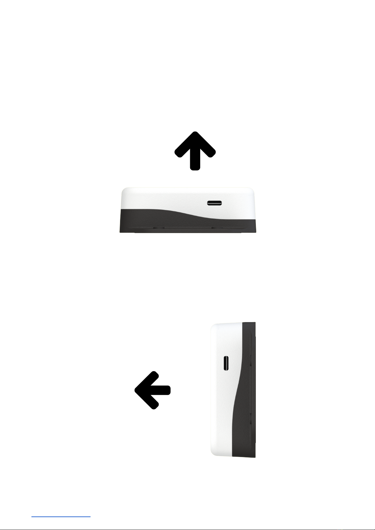
4. ACTIVATION
4.1. PROCESS
The TRACK devices that come from production are in a dormant state and will require an
activation process to be done so that they can install their latest software to start operating.
(Note: In some cases, the device may have already been activated prior to being sent to you. If
that is the case, you can skip this section and go straight to mounting the device (See SECTION
5). You can check if your device has already been activated by logging into the Silica Platform
with your username / password (See SECTION 7.1). The device will be visible in the Home
screen.)
The process for activating the device is relatively simple, it requires you to swipe a strong
magnet over the top of the device (see Table 2 for the specific area) after which the device's LED
will light up (See SECTION 3.2 for more information on what the LED lights mean) and it will
download its intended software from the OTAU server. After downloading & installing the
software, the device will then send a STARTUP message to the Silica Platform after which it is
ready to be used.
See Table 2 (below) that shows the location on the device of where you should swipe the
magnet to activate it.

Table 2. Overview of the area on the device where the magnet should be swiped to activate it.
TRACK ACTIVE
TRACK SOLAR
4.2. BUTTON & LED FUNCTIONALITIES
The below information shows the Button behaviour / LED responses and what they mean. This
information is for the two different types of TRACK devices (ACTIVE / SOLAR) that are currently
available.
4.2.1.TRACK ACTIVE
Table 3. Overview of primary functions and required actions to trigger a function in a TRACK
ACTIVE device. The LED response is given.
Function
Action
Image
LED Signal
Pulse
Single press
All four LEDs
fade in/out in
white.


Start test-rig application
-
Top LED
flashes in
purple for 1.5
seconds
4.2.2.TRACK SOLAR
Table 4. Overview of primary functions and required actions to trigger a function in a TRACK
SOLAR device. The LED response is given.
Function
Action
Image
LED Signal
OTAU Start
Magnet Reset
White LED
pulses 5 times
Reset
*Only applicable if
TRACK hasn’t carried out
an OTAU in the last 24
hours, otherwise it will
start an OTAU with a
magnetic reset.
Magnet Reset
Orange LED
fades in/out

OTAU Fail
None
Red LED
pulses 5 times
Start test-rig application
-
Purple LED
flashes for
1.5 seconds
5. MOUNTING
Depending on whether your TRACKs are equipped with Flanges or No Flanges, your mounting
solutions will vary. This section provides our recommendations on these two mounting options
as well as the required orientation for optimal performance.
5.1. FLANGES
A TRACK with flanges will feature 2 screw holes on either side of the device, an example is
shown in the image below.


5.2. NO FLANGES
Non-flanged TRACK models will have a regular base without lateral screw holes as shown in the
image below.
It is recommended to use 2 strips of 3M Tape (VHB or GPH) - or alternatively LSE series tape
for applying to some plastics like HDPE - each 5.0 x 1.9 cm long attached to the back of the
tracker as shown in the image below. It is important that the device is attached to a smooth,
non-curved and clean surface on your asset. The surface should be at least 80x80 mm.
5.3. ORIENTATION
For optimal GPS positioning, SODAQ TRACK should be placed facing upwards, in a horizontal
orientation. This maximises the number of satellites that the device can detect.
If a horizontal orientation is not feasible, a vertical orientation is the second preference. Note
that with this orientation, GPS positioning accuracy can diminish in comparison to a horizontal
orientation.

5.4. SURROUNDING STRUCTURES
GPS accuracy is influenced by surrounding structures; buildings, trees, tunnels, mountains and
vehicles. When mounting TRACK onto your assets, it is recommended to ensure its view of the
sky isn’t obstructed by metallic structures, for example in a metal container or a vehicle.
5.5. HEAVY IMPACTS
The IP67 enclosure of TRACK can withstand strong jets of water (e.g. for use on ship decks)
and is totally protected against dust. However with extremely powerful impacts there is a risk
that the device will fall off or take some damage. when mounting TRACK onto your assets,
select a placement with minimal risk of powerful impacts to ensure operational longevity.
6. DEVICE BEHAVIOUR AND OPERATING PROFILE
SODAQ TRACK is designed to operate as a low power tracking device. There are numerous
mechanisms used by TRACK to send uplinks in an autonomously manner, which is primarily
based on motion using the onboard accelerometer. This behaviour allows TRACK to minimise
power consumption and to communicate the most relevant information about your assets.
TRACK alternates between two primary operational states while tracking; Idle Mode and Active
Mode.
6.1. IDLE MODE
The Idle Mode is the baseline state of TRACK and will always revert to this state when no
activity is taking place. When TRACK is stationary, it remains in deep sleep until it needs to wake
up to send an IDLE message. These messages (or uplinks) are communicated at a fixed interval
of once a day, for example. The idle interval can be configured to reduce or increase the
message frequency. Refer to Section 6.8 - Configuration for more information on configuring
idle messaging.
6.1.1.MESSAGE DOUBLING
To further minimise power consumption, the TRACK device has a feature called message
doubling. This feature will double its idle interval when your asset remains stationary for a
period longer than the device’s current idle interval. For example, if the starting idle interval is 1

message per day, the next message will be sent in 2 days, then 4 days and so on. However, once
motion is detected, the idle interval will be reset.
The maximum interval for this feature can be configured using a downlink with intervals of 1 day
up to 32 days.
6.2. ACTIVE MODE
Using the onboard accelerometer, TRACK can detect the movement of your asset, for which it
enters the Active Mode. A MOTION START message is sent to indicate motion has occurred.
With continuous motion, TRACK will consistently send uplinks at the rate of its active interval.
The default configuration for the active interval is 30 minutes.
6.2.1.FLIGHT MODE
When your asset is moving, particularly when in an aircraft, the TRACK can be configured not to
send messages throughout the asset's journey (while it is in motion). With Flight Mode ON,
TRACK will send a MOTION START message once it first detects motion. When your asset
reaches its final destination and arrives at a full halt, the TRACK will wait for a period of time to
confirm that it has stopped moving, after which it will send a MOTION STOP message to report
the final location after your asset’s journey.
6.2.2.MOTION TRIGGER
The onboard accelerometer can be toggled switching the Motion Trigger configuration.
With Motion Trigger OFF, TRACK will only stay in Idle Mode. TRACK will communicate at a fixed
time interval (the idle interval) regardless of any motion occurring with your asset. Please note
that if Motion Trigger is switched off, Message Doubling is switched off by default to avoid
extended periods of no communication from the device.
6.3. POSITIONING TYPE
The method of positioning used by TRACK dictates the overall accuracy of its reported location.
Positioning Type can be configured respectively for both idle and active messages. It is
important to note that Cell and WiFi location are resolved in the SILICA Platform, meaning they
will only be formatted as latitude and longitude coordinates once they have been processed in

the platform. The SILICA Platform gives preference to positioning type in the order of GPS, WiFi
and Cell.
A detailed overview is given in Table 3 below.
Table 5. Indication of preference, accuracy and reliability for positioning types
Type
Preference
Accuracy
Reliability
GPS
High
5 - 100 m
●Unreliable inside buildings (Requires Line
of Sight or Near Line of Sight to the sky)
●Accuracy influenced by surrounding
metallic structures
●Most power consuming positioning
method
WiFi
Medium
20 - 200 m
●Depends on coverage of access points in
the surrounding area.
●Accurate in urban areas
●Less reliable in rural areas
●Up to 6 WiFi access points reported
Cell
Low
100m - 2 km
●Default fallback
●Always available with a successful uplink
message.
●Accuracy up to the nearest Cell Tower.
6.4. TRIGGER REASONS
Trigger reasons indicate the mechanism that triggered an uplink message. There are 5 trigger
reasons, all shown in the Table below.
Table 6. Trigger reason IDs (software encoding), labels and description
ID
Label
Description
0
Startup
An initial message will be sent when the device is:
1. Activated with a magnet
2. Switched on again after recharging the battery
3. Reboot of the device
Note: Idle Positioning Type is used for Startup messages.
1
Button
For TRACK ACTIVE only, a button press will trigger a message using
the Idle Positioning Type for location.
2
Idle
An Idle Message is sent every X hours/days, as prescribed by the Idle
Interval. Positioning used for Idle Messages can be configured by the

user.
3
Motion Start
TRACK will send a Motion Start message when it detects motion after
its Active Interval time.
Note: If GPS is configured, then the Motion Start message is only sent
after it gets a GPS location from the Satellites, this can take up to 2
minutes depending on coverage and interference.
4
Motion Stop
TRACK sends a Motion Stop message after coming to stop and
confirming that there is no motion detected.
6.5. CONFIGURATION
There are 7 configuration parameters which can be modified to control your TRACKs’ behaviour.
For details on how to update, refer to Section 7 - SILICA PLATFORM. It is important to note that
the battery performance is strongly dependent on configurations and how often your asset is
moving. It is important to select the configurations that work with your use case while
optimising power consumption. Our team can support you in identifying opportunities to
optimise battery life, for further support please contact your Account Manager. Table 6 provides
an overview of all configuration options along with their accepted value ranges.
Table 7. Configuration parameters, the default values and the accepted ranges are shown
Configuration
Default
Min
Max
Idle Interval
24 hours
6 hour
32 days
Idle Positioning Type
Cell & WiFi
Cell
Cell, Wifi & GPS
Active Interval
30 minutes
5 minutes
24 hours
Active Positioning Type
Cell & WiFi
Cell
Cell, Wifi & GPS
Message Interval Doubling
OFF
OFF
ON
Flight Mode
ON
OFF
ON
Motion Trigger
ON
OFF
ON
Table 8. Available configuration options for positioning types and their power consumption

Configuration
Description
Power Consumption
Cell Only
Cell location always used
Low
Cell and WiFi
WiFi attempted first, cell location as
fallback
Medium
Cell and GPS
GPS attempted first, cell location as
fallback
Medium
Cell, WiFi and
GPS
GPS attempted first, WiFi is first
fallback, Cell is second fall back
High
Configuration changes are only implemented on a TRACK after it sends an uplink to the SILICA
Platform. Once a configuration change is made within the SILICA Platform, a downlink with the
new configurations is queued for the device and is sent upon its next uplink.
When handling devices in the field, it is useful to force a configuration change by triggering a
message from the device, this can be done by pressing the button (ACTIVE only) or moving the
device to trigger a motion message. The SILICA Dashboard allows you to monitor the update
status of your devices and make these configuration changes.
Please refer to the next section for more details.
7. SILICA PLATFORM
SILICA is a cloud-native IoT platform hosted on AWS where all traffic from TRACK devices are
managed. An application handles all the processing to make the data available for customers
via the SILICA Dashboard.
Below is an overview of the primary applications running on the platform.
Table 9. Applications running on the SILICA platform that handle TRACK’s data
Application
Description
UDP Listener
UDP Listener receives raw UDP payloads from TRACK units over
Private APN connection. Binary data is decoded, preporcessed,
cell/wifi lookups are carried out, then stored in the database for
later use. The listener handles device configurations by sending
downlinks back to the device while it is connected to the network.

Data Forwarder
Within the UDP Listener, live payload data can be posted to the
customer’s application over an HTTPS request. The data is
provided in JSON. Please contact your Account Manager for
further details.
TRACK Dashboard
User interface providing overview of location and status of
devices, enables device configurations.
TRACK API
For integration of SILICA backend with customer application.
Enables customers to retrieve device metadata, telemetry data
and to update configurations from their own application. Contact
your Account Manager for further details.
Over-the-Air
Updates
Central firmware management system for all TRACK devices. The
system is used to provide devices with their latest firmware when
activated and when a new firmware version is available. To get an
overview of the features in current software versions, please
contact your Account Manager.
7.1. DASHBOARD
When a TRACK is purchased, a SILICA account is created for the primary contact in your
organisation. Upon creation of this account, you will receive an email with your username and
password. You should then carry out the following steps:
1. Go to https://trackdash.sodaq.com
2. Enter your username and temporary
password, then click Login
3. Enter your new password,
confirm by clicking Update Password
4. You should now be logged in

7.1.1.HOME PAGE - FLEET OVERVIEW
An initial glance at your entire TRACK fleet is given in the Home Page screen.
Here you can feasibly identify the latest location of your assets and identify TRACK units that
require further inspection. Table 10 below specifies the available functionalities in this screen.
Table 10. Available features on the Fleet Overview screen
Feature
Description
Map Clusters
When zoomed out of the map view, nearby points are clustered
together and represented by the number of assets within a given
region to see an assets’ location, zoom in to see a precise location for
your asset.
Map Points
Last reported location by TRACK is shown with a point feature on the
map. There is one point for every TRACK owned by your organisation.
Hovering your mouse over a point will show a popup with more data.
Clicking on the point will take you to the historical perspective of the
TRACKin the Device Overview screen
Base Map Layer
It is possible to change the base map layer. Options include Terrain,
Satellite and White & Grey.
Devices Table
A table list shows all your devices with information about each
tracker:

●Name - a unique name tag per device. It consists of a text
name + last 6 digits of the imei (International Mobile
Equipment Identity)
●QR Code - unique alphanumeric code printed on the top casing
of all TRACK units
●Last Active - datetime of the last uplink seen from the device
●MCC / MNC - Mobile Country Code and Mobile Network Code
All the data can be filtered and sorted using the components in the
table headers, for example you can search for a device by name or qr
code to filter through the list, or you can sort your list by the time they
were last active.
You can also click on a specific device to open its Device Overview
Page and see its location history.
7.1.2.DEVICE OVERVIEW
The Device Overview page provides a full historical perspective of an individual TRACK device.
There are various components on this screen that allow you to explore the data through the
map, table and charts.
Table of contents


