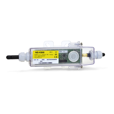
SOFTLINK NB-K430 User manual

Contents
1 Introduction 1
1.1 NB-IoT mobile data services ......................................... 1
1.2 Module usage ................................................. 1
1.3 Hardware features and power supplying .................................. 2
2 Technical parameters overview 3
3 Configuration of the NB-K430 module 4
3.1 Setting of NB-K430 module parameters by configuration cable ..................... 5
3.1.1 List of NB-K430 module configuration parameters and commands ............... 5
3.1.2 ”System commands” group for control of module basic functions ................ 7
3.1.3 ”Configuration” group of commands for writing of configuration ................ 8
3.1.4 ”System commands” group for general diagnostics ........................ 8
3.1.5 Commands for setting of watermeter reading ........................... 9
3.1.6 Commands for setting of message broadcasting system ...................... 12
3.1.7 Displaying of other operational entries in the list of parameters ................. 15
3.2 Setting of parameters by using of optical converter ............................ 17
3.3 Remote setting of module parameters through the NB IoT back channel ................ 20
3.3.1 Overview of module configuration parameters ........................... 21
3.4 The NB-K430 module data messages .................................... 22
3.4.1 Structure and types of data messages ............................... 22
3.4.2 Description of INFO message .................................... 23
3.4.3 Description of TRAP message .................................... 24
3.4.4 Encryption of messages ....................................... 25
4 Operational conditions 26
4.1 General Operation Risks ........................................... 26
4.1.1 Risk of mechanical and/or electric damage ............................. 26
4.1.2 Risk of premature battery discharge ................................ 26
4.1.3 Risk of damage by excessive humidity ............................... 26
4.2 The condition of modules on delivery .................................... 27
4.3 Modules storage ............................................... 27
4.4 Safety precautions .............................................. 27
4.5 Environmental protection and recycling .................................. 27
4.6 NB-K430 module installation ........................................ 27
4.7 Module and meter replacement ....................................... 29
4.8 Module dismantling ............................................. 30
4.9 Functional check of the module ....................................... 30
4.10 Operation of the NB-K430 module ..................................... 30
5 Troubleshooting 31
5.1 Possible causes of module failures ...................................... 31
5.1.1 Power supplying failures ....................................... 31
5.1.2 System failures ............................................ 31
5.1.3 Failures of communication with NB-IoT network ......................... 31
5.1.4 Failures of communication with watermeters ........................... 32
5.2 Troubleshooting procedure .......................................... 32
6 Additional information 33
List of Tables
1 Overview of NB-K430 module technical parameters ............................ 3
2 Overview of NB-K430 module configuration parameters ......................... 21
NB-K430 i

List of Figures
1 View of the NB-K430 module ........................................ 2
2 Table for selection of message content (”mask”) .............................. 11
3 NB-K430 module configuration table .................................... 17
4 Basic forms of NB-K430 module in ”SOFTLINK Configurator” application .............. 19
5 Network setting form and list of watermeters in reach acquired by RADAR function ......... 19
6 Preview of ”NEP coding table” for coding of variables in WACO system ................ 22
7 Set of NB-K430 module components with stick antenna ......................... 28
8 Detail of NB-K430 module PCB ...................................... 28
NB-K430 ii

1 Introduction
This document describes features, parameters and setting possibilities of the NB-K430 module, which is used for
remote reading of iPERL series watermeters by Sensus, that are equipped with 430 MHz data transmitter, and for
resending of read data to the superior remote reading system via data services of NB-IoT operator.
1.1 NB-IoT mobile data services
Mobile data services NB-IoT are global data services provided by some operators of GSM services. The
services are focused on the communication with a huge quantity of devices, that transfer only an extremely limited
volume of data. Networks with such purpose and features are commonly labeled as ”Internet of Things”, or by its
acronym ”IoT”. NB-IoT (”Narrow Band Internet of Things”) is an open standard developed by 3GPP organization
(3rd Generation Partnership Project) which is concerned with standardization in the GSM network development.
NB-IoT is a cellular technology based on the LTE, that was developed specially for wireless communication with
terminals of IoT category, that produces only limited volume of data, but they are miniature, inexpensive, with
a very low energy consumption and they are commonly installed in the places with high demands on the signal
coverage. Typical example of such device is a reading module of the water/gas/electro-meter installed in the
basement without electricity, that should be able to run reliably many years on the internal battery even in weak
signal conditions, where other services fail.
NB-IoT technology maximally utilizes technological infrastructure of LTE data services in licensed radio band.
Combination of narrow frequency band and the most advanced modulation techniques enable increasing of receiver
sensibility to the -135 dBm level, so that an existing infrastructure of mobile operator provides global coverage
with high signal penetration even in build-up urban areas. Thus, the service is available in the places, where IoT
category devices are typically installed - in shafts, distribution boards and cellars.
Terminal devices are identified in the network by standard SIM of GSM operator. Global system of SIM evidence and
single communication standard enable providing of international services (roaming). Bi-directional communication
is carried by standard Internet protocol with UDP transport layer. Messages are transferred from the GSM operator
network to the IoT-terminal operator through the designated data gateway (Access Point - AP) either to public
Internet, or to operator’s private IP network (i.e. same way as any similar mobile data services). Addressing and
routing details depend on the network configuration and policy of particular GSM operator. Typical example of
addressing and routing is a solution, when the GSM network automatically assigns private IP addresses to IoT
terminals, IP-packets with messages are routed through the private IP network to a single Access Point, where
they are re-addressed and resend through a single pre-arranged public IP-address to the public Internet. The IoT
terminal assigns packets by target server public IP-address, that is preset in its configuration. Target system can
identify original source of the message by using of device unique identifier (IMEI), which is a requisite part of the
message content.
1.2 Module usage
The NB-K430 module can be used as local communication gateway for remote reading of Sensus iPERL-series
watermeters. The module receives regular radio messages with readings (”Bubble Up” messages) from watermeters
in its radio-reach and stores the readings to its memory. In pre-defined intervals the module broadcasts aggregate of
received data to the superior system of remote reading (AMR) in form of radio-messages of NB-IoT service (”INFO”
messages).
The NB-K430 module can by used for remote reading up to 10 iPERL watermeters placed in its radio-reach
(that is up to hundreds meters). Each watermeter transmits BUP messages with fixed period of 15 seconds. The
module receives data from watermeters in regular ”receiving windows” (e.g. every 60 minutes), that are opened
with preset ”reading period”. Received data from each receiving window are stored to the module memory. With
pre-defined broadcasting period (e.g. 12 hours) the module broadcasts one NB-IoT message with aggregate data
from all receiving windows to the superior server. This way of communication is a highly effective, as it is optimized
from energy consumption point of view, as well as from point of view of NB-IoT services expenses.
The module can also work in on-line mode, when the data are broadcasted immediately after each receiving
window.
Each module has its table of read watermeters, where there are IDs (serial numbers) of meters that should be read
by the module. If there are other watermeters in the reach, their BUP messages are ignored. The module supports
receiving and transmitting of messages either in open mode, or in encrypted mode. The module can re-send
original watermeter alarms (Sensus alarm flags) as well as its own alarm messages.
NB-K430 1

Content of INFO-messages is configurable. The messages contain identification and current statuses of module
parameters (uptime, battery voltage, processor temperature..), list of read watermeters, timestamps of reading
periods, and counter values of all watermeters in each reading period (including alarm flags). One message can
contain up to 120 readings, that means values from 12 reading periods even in case of full module capacity of 10
read watermeters (e.g. reading every hour and broadcasting data from 10 meters two times a day).
These messages are handed over to the application server with using of NB-IoT service of GSM provider. The data
are transferred in form of standard IP/UDP packets, that are routed to the server of remote reading application
operator through the designated Access Point of GSM provider. Application server receives the messages and
performs their decoding, storing and further processing.
The NB-K430 module supports bi-directional communication and it is able to receive through the network
messages of ”SET” type, generated by remote computer. These messages can be used for setting of module
parameters from the remote server.
1.3 Hardware features and power supplying
The module is enclosed in humidity-proof plastic casing with IP65 degree of protection and can be used in interiors
as well as in exteriors. The casing is designed for mounting on the wall or other construction element (beam,
pipe...). Module can be treated with an additional sealing by high-adhesion silicon filling, that can ensure proof
against inundation by water (IP68 grade). If this treatment is required from the manufacturer, it must be ordered
separately.
The module is power supplied by internal battery with up to 6 years lifetime for frequency of 4 broadcastings
per day (one message can contain up to 120 readings). Battery lifetime can be negatively influenced by shorter
broadcasting period, or by storing and operation in sites with the temperatures exceeding the recommended range.
The module is equipped with a SIM-holder for ”Micro-SIM” (3FF) format of SIM-card (15 x 12 x 0,76 mm). SIM-
holder is placed inside the module on the PCB. The module can be ordered with embedded SIM (eSIM) of chosen
GSM operator.
The module can be controlled and configured either by configuration cable, or wirelessly, by infra-red optical
converter. The module is equipped with the special circular aperture (”peephole”) for magnetic fixing of the optical
converter. The module can be also configured remotely, with using of back channel of bi-directional communication.
External appearance of the NB-K430 module is shown in the figure 1.
Figure 1: View of the NB-K430 module
NB-K430 2

2 Technical parameters overview
Overview of NB-K430 module technical parameters is shown in the Table1below.
Table 1: Overview of NB-K430 module technical parameters
RF subsystem parameters
Frequency band 800 MHz (RX/TX) 791-821 / 832-862 MHz
Frequency band 850 MHz (RX/TX) 869-894 / 824-849 MHz
Frequency band 900 MHz (RX/TX) 925-960 / 880-915 MHz
Modulation GMSK, 8PSK (adaptive)
Bandwidth 180 KHz
Transmitting power 200 mW
Receiver sensitivity 135 dBm
Communication protocol NB IoT (bi-directional)
Transmission speed 0,35 ÷240 Kbps (adaptive)
Antenna characteristic impedance 50 Ω
Antenna connector SMA female
iPERL receiver parameters
Carrier frequency 433,7429 MHz
Modulation 2GFSK
Receiver sensitivity 110 dBm
Antenna integrated
Max. number of read watermeters 10
Configuration interface RS232
Transmission speed 9600 Baud
Operation mode asynchronous
Transmission parameters 8 data bits, 1 stop bit, none parity
Signal level TTL/CMOS
Optical configuration interface
Transmission speed 115 200 Baud
Optical wavelength 870 nm
Optical interface specification IrPHY 1.4 standard
Power supplying
Lithium battery voltage 3,6 V
Lithium battery capacity 13 Ah
Weight and dimensions
Length 145 mm
Width 45 mm
Height 105 mm
Weight cca 300 g
SIM-card format (15x12x0,76)mm) ”Micro-SIM”
Storage and installation conditions
Installation environment (by ˇ
CSN 33 2000-3) normal AA6, AB4, A4
Operation temperature range (-20 ÷40) ◦C
Storage temperature range (0 ÷40) ◦C
Relative humidity * 95 % (w/o condensation)
Degree of protection * IP65 or IP68
* modules treated by additional silicon filling are waterproof with IP68 degree of protection.
NB-K430 3

3 Configuration of the NB-K430 module
Configuration parameters of the NB-K430 module can be displayed and changed from the common computer (PC)
by one of these methods:
- with using of ”USB-CMOS” converter and configuration cable connected to the module;
- wirelessly, with using of ”USB-IRDA” or ”BT-IRDA” converter;
-remotely, by using of bi-directional communication system.
Technique of interconnection of the module with configuration computer and general rules of configuration are
described in detail in the chapter 2 of ”Configuration of wacoSystem product family devices”, that can be
downloaded from the producer website:
www.wacosystem.com/support/
www.softlink.cz/en/documents/
The description and meaning of all configuration parameters that can be checked and changed by cable can be
found in the section 3.1 ”Setting of NB-K430 parameters via configuration cable”.
Description of interconnection of the converter with PC (”USB-IRDA”) or smartphone (”BT-IRDA”) and gen-
eral rules of configuration with using of optical converters are described in the chapter 3 of above mentioned
manual ”Configuration of wacoSystem product family devices”. The description and meaning of the parameters
that can be changed by optical converter can be found in the section 3.2 ”Setting of parameters by using of optical
”IRDA” converter”.
Principles and short description of communication through the NB-IoT back channel can be found in para-
graph i 3.3 ”Remote setting of module parameters through the NB IoT back channel”.
NB-K430 4

3.1 Setting of NB-K430 module parameters by configuration cable
In following part of the document there is a description of these parameters of the NB-K430 module, that can be
displayed and examined from PC connected to the module by configuration cable. Some of the parameters can be
changed by configuration commands entered ”from the console”.
3.1.1 List of NB-K430 module configuration parameters and commands
List of all configuration parameters of the module can be displayed by entering of ”show” command and pressing
of ”ENTER” key. The following list of parameters will display in the terminal window:
mon#show
----- Configuration -----
Timezone : 1
Server IP : ’172.168.0.20’
Server port : 4242
My src port : 2000
Reply to server : no
APN : ’’
Max session time 172800 sec - 2d, 0:00:00
Send periode : 240
Hist. periode : 60 min.
each meter 4 records, max. is 120 recs
Send mask is 3 : SID, Alarm
Next send : 239 min.
Data will be unencrypted
Sensus meters :
ID[0] : 130551475
ID[1] : 130551473
ID[2] : 130551474
ID[3] : 130551476
ID[4] : 130551477
-- 433Mhz modem --
No. sent : 0 msg(s)
No. recv : 2 msg(s)
No. recv error : 0 msg(s)
-- Narrow band modem --
Next send : 239 min.
No. sent : 3 msg(s)
No. recv : 0 msg(s)
Modem state : 4 - ready
Session count : 1
Session timeout : 172664 sec - 1d, 23:57:44
Modem IMEI : 867724031580613
SIM CCID : 89882390000036330010
SIM IMSI : 901288001028645
Last RSSI : -79 dBm
Conf. version : 19
SW version 1.01, date Apr 1 2020
mon#
List of all configuration commands (”HELP”) can be displayed by entering of ”?” command into the command
line and pressing of ”ENTER” key. The following list of commands will display in the terminal window:
NB-K430 5

mon#?
--- System commands ---
deb : Show or set debug level
ta : Show tasks
mb : Show mail boxes
du addr : Dump memory
rb addr : Read byte from addr
rw addr : Read word from addr
rd addr : Read dword from addr
sb addr val : Set byte on addr
sw addr val : Set word on addr
sd addr val : Set dword on addr
port : Show port [a,b,..]
show : Show info
write : Write configuration to flash
cread : Read configuration from flash
clear : Clear configuration and load defaults
--- 433 commands --- ---
power : Show or set 433 power (1 - 5)
mr : Modem receive mode 0 - off, 1 - on
mt test time : Set test on modem, 1 - TX carrier, 2 - TX sync, time is in second, default 10
ms : Get modem state
mi : Get modem info
recvwin : Set receive window in sec.
radar : show radar
hdata : show history data
--- Narrow band ---
server : Server IP address
sport : Server UDP port
sreply : Send reply to server
apn : Access Point Name
sess : Set max session time in minutes
tshort : Set modem short timeout
tlong : Set modem long timeout
tconn : Set modem connection timeout
at : modem command
--- Utils ---
tz : Time offset in hours
ppm : Set RTC ppm
time : Show or set rtc time, set as BCD : 0x102033 is 10:20:33
date : Show or set rtc date, set as BCD : 0x171231 is 2017-12-31
uptime : Show uptime
sens : Show sensors
mfreq : Set or get xtal frequency correction
sfreq : Set frequency correction from analyzer in Hz, example : 433725000
cfreq : Set +- frequency correction, 1 = 1Hz
sendp : Send x NB messages
send : Send NB message
smask : Send mask bits, 0 - SID, 1 - Alarm, 2 - RSSI ,default 7 - all
periode : Change periode of send 0 - disable, >0 periode in minutes
hist : History periode 0 - disable, >0 periode in minutes
ekey : Set encrypt key NEP, point ’.’ no encrypt
skey : Set encrypt key Sensus
sid [index] [value] : Set Sensus meter ID
info : Show or set manuf. info string (0-30 chars)
reset : Reset device
? : Show this help
Overview of configuration parameters with short description of their meaning can be also found in table 2on the
page 21. The meaning of individual parameters and detailed description of their usage can be found below.
NB-K430 6

3.1.2 ”System commands” group for control of module basic functions
This group of commands enables control of basic functions of the module. There are following commands:
reset command for module reset
send immediate sending of radio message
sendp immediate sending of series of messages
sens show current values of internal sensors (temperature, voltage..)
uptime show system uptime from last reset
info setting of individual module description
The command ”reset” performs the module reset. After each reset the system starts with the parameters that are
stored in FLASH memory. If the current configuration should be used after reset, it is necessary to store it into the
FLASH before reset (see paragraph 3.1.3). Example of using of ”reset” command:
cfg#reset
-- Reset code 0x14050302 --
PIN Reset
SFT Reset
SW version 0.01, date Jan 18 2019
Monitor started ..
mon#
The command ”send” can be used for immediate (”out of turn”) transmitting of the standard information message
with measured values. This command can be used for checking of radio signal availability during the system
installation, or for any adjustments and testing of the module. The command makes possible to send the information
message anytime without necessity to change the transmission period or without waiting until the message will be
sent spontaneously within the pre-set period. Example:
cfg#send
Sending ...
send [1] msg 255
mon#
The command ”sendp” can be used for immediate transmitting of series of standard messages with 1-minute
interval. This command can be used for checking of radio signal availability during the system installation. It could
enable checking of connection also after closing of mounting rack, or after leaving of watemeter shaft. Number of
transmitted messages is set by parameter (number) after command, the first message is transmitted immediately
after command. Example of sending of series of 5 messages:
cfg#sendp 5
sending 5 msgs
mon#
The ”sens” command can be used for displaying of current values of A/D converters measuring physical quantities
(battery voltage, temperature...). This command is intended only for module checking and diagnostics.
cfg#sens
-- Sensors --
CPU : 25.8 ◦C
VDA : 3.003 V
VBAT : 3.561 V
Sensor type 0
mon#
The ”uptime” parameter value shows the time interval passed from the last device reset in seconds so that the
exact moment of the last module reset can be recognized by this parameter. The parameter is of ”read only” type.
Example:
cfg#uptime
Uptime 0d, 0:13:26
mon#
NB-K430 7

The ”info” command can be used for setting of individual description/label of the module. Up to 30 alphanumeric
characters can be entered. The label will be displayed in the ”Info text” field of the optical configuration form. The
label can contain any identification data (installation site code, customer code, meter serial number. Example of
module individual text setting:
cfg#info NB-X 123456
Change manuf info from : ’’ to : ’NB-X 123456’
mon#
3.1.3 ”Configuration” group of commands for writing of configuration
The module contains two sets of configuration: operating configuration and saved configuration. At the start of the
system the module copies saved configuration to operating configuration, with which continues to work. If the user
changes configuration parameters, it does so only in operating configuration.
If the current operating configuration was not stored to FLASH memory, the module returns to the saved config-
uration after reset. If the parameter should be changed only temporarily (for example shorten of the broadcasting
period during installation), it is not necessary to save operating configuration into FLASH memory (after finishing
a work the module can be returned to normal configuration by its reset). If the parameter should be changed
permanently, there is necessary to save configuration to FLASH memory.
If operating configuration corresponds to the saved set (ie. there are no differences between commands in FLASH
and in the operating set), the module will ”report“ prompt in the format ”mon#”. If operating configuration was
changed so that it no longer matches to the saved set, the module will report prompt in the format ”cfg#”.
Every time the current configuration is saved into FLASH memory the value of the ”Configuration version” param-
eter increases by one and the prompt changes to ”mon#”. The parameter resets to zero by erasing of FLASH.
Current operating configuration can be displayed by using of ”show” command (see paragraph 3.1.1):
cfg#show
Current operating configuration can be rewrite the to FLASH memory by using of ”write” command:
cfg#write
Writing config ... OK, version 13
mon#
Reading of the configuration from FLASH memory can be done by using of ”cread” command:
cfg#cread
Reading config ... OK, version 13
mon#
The configuration can be erased in Flash memory by using of ”clear” command:
cfg#clear
Clearing config ... OK, version 13
mon#
This command deletes all configuration parameters from the FLASH memory, so it is necessary to set them again.
If after erasing all parameters in FLASH memory the module goes to reset, default set of parameters (configured
in the program of the device) is duplicated to FLASH memory. There is only one exception - frequency constant
keeps the actual value also after cleaning of FLASH memory by ”clean” command.
This command is recommended to use only by users with good knowledge of the system or after
consultation with the manufacturer.
3.1.4 ”System commands” group for general diagnostics
Commands ””deb”, ”ta”, ”mb”, ”du addr”, ”rw addr”, ”rb addr”, ”rd addr”, ”sw addr val”, ”sb addr
val”, ”tshort”, ”tlong”, ”port”, ”ppm” and ”at” are used for troubleshooting and repair of the device in
a factory. Manufacturer strongly recommends not to use these commands during common operation.
NB-K430 8

Another group of commands are intended for factory setting and diagnostics of 433 MHz transceiver sub-system
(RF-modem), that serves for receiving of data from Sensus iPERL watermeters. There are following commands:
mt test time launch of testing transmission (setting and diagnostics)
ms display RF-modem internal status (diagnostics)
mi display RF-modem internal registers (diagnostics)
mfreq frequency constant setting (setting)
sfreq frequency tunning by RF-analyzer output (setting)
cfreq frequency constant correction (setting)
It is strongly recommended not to use these commands during common operation.
3.1.5 Commands for setting of watermeter reading
The module is equipped with internal 433 MHz modem, that serves for receiving of data from Sensus iPERL
watermeters. In regular operation the modem is periodically (with preset reading period) switched to receiving
mode for 45 second time interval (called ”receiving window”), when BUP radio-messages from all watermeters in
radio-reach are received. After receiving window the modem is switched off to save battery energy.
This group of commands serves for setting of reading data from Sensus iPERL watermeters. There are following
commands:
skey setting of encryption key for decrypting of watermeter messages
mr manual switching of 433 MHz modem to receiving mode
recvwin open 433 MHz receiving window for preset time interval
radar show list of watermeters in module radio-reach (”RADAR” mode)
sid [index]
[value]
setting of watermeter IDs for reading (reading list)
hist historical readings storing period
hdata displaying records in memory of historical readings
smask setting of content (selection of transferred information)
The command ”Sensus encryption key” is used for setting of the encryption key for decryption of messages
from Sensus iPERL watermeter (if the messages are encrypted). The AES-128 encryption key of 16 bytes length
is entered by using of ”skey” command, followed by the string of 16 bytes that can be entered in a decimal
or hexadecimal format same way as encryption key for NB-IoT communication (see using of ”ekey” command in
paragraph 3.1.6 below).
Receiving mode of 433 MHz modem can be manually switched by using of ”mr [1/0]” command. By entering of
”1” parameter the receiver is switched on, by entering of ”0” parameter the receiver is switched off. In the time
interval, when the receiver is active, all messages from all watermeters in the radio-reach appear in the window of
serial communication program. This way it can be surveyed, which meters are in the reach and with what frequency
and reliability is their signal received. The receiving window can be opened for desired time, until it is manually
closed by command with ”0” parameter. Example of opening and closing of receiving window:
mon#mr 1
Receive 0
mon#Recv :
00 61 07 c8 0e b4 48 48 48 48 48 76 7c d2 .a....HHHHHv|.
Recv ID 130551476, Val 224, status 0, rssi -67, prev 0:01:00 ago
Recv :
00 21 07 c8 0e b1 80 67 bf bf bf c2 f5 70 .!.....g.....p
Recv ID 130551473, Val 3362, status 0, rssi -69, prev 0:01:01 ago
Recv :
00 52 07 c8 0e b2 67 37 37 37 37 84 6a 77 .R....g7777.jw
Recv ID 130551474, Val 8, status 0, rssi -81, prev 0:01:00 ago
Recv :
00 51 07 c8 0e b3 68 68 68 68 68 9e 2b 1d .Q....hhhhh.+.
Recv ID 130551475, Val 0, status 0, rssi -63, prev 0:01:00 ago
mon#mr 0
Receive 0
mon#
NB-K430 9

By using of ”recvwin [time]” command the 433 MHz modem can be switched to ”RADAR” mode for requested
interval. In this mode the modem receives messages from all watermeters in the reach and creates ”RADAR” table,
where each watermeter has only one row (regardless the number of received messages). Thus, this table practically
contains the list of all watermeters in the radio-reach of the module. Length of receiving window is set by [time]
parameter of the command. Example of switching of 433 MHz modem to the ”RADAR” mode for 60 seconds time
interval:
mon#recvwin 60
Set receive window on 60 sec.
mon#
After expiring of [time] period the ”RADAR” table content can be browsed by using of ”radar” command:
mon#radar
Show radar :
id 130551474, rssi -75, time 2019-01-01, 0:01:25+01
id 130551473, rssi -69, time 2019-01-01, 0:01:21+01
id 130551476, rssi -69, time 2019-01-01, 0:01:17+01
id 130551477, rssi -54, time 2019-01-01, 0:01:13+01
id 130400388, rssi -103, time 2019-01-01, 0:01:12+01
id 130551475, rssi -62, time 2019-01-01, 0:01:11+01
mon#
As evident form the example, during the receiving window the module received messages from six Sensus iPERL
watermeters. Each record contains watermeter serial number (id), radio-signal strength in dB (rssi) and message
receiving time (time). Stored values come from the first received message from the watermeter in the receiving
window.
The ”Set Sensus meter ID” variable serves for setting of list of Sensus iPERL watermeters, that is intended
to be read by the NB-K430 module. Each record to the list could be created by using of ”sid [index] [value]”
command, where meter ID (serial number) is linked with meter index (0 - 9).
Example of command for entering of iPERL watermeter with ”130551477” serial number into the list of read meters
under index ”4”:
cfg#sid 4 130551477
Sensus ID[4] changed from : 0 to : 130551477
mon#
Current list of read watermeters is stated in the list of all configuration parameters. The list can be also displayed
by using of ”sid” command without parameters:
mon#sid
Sensus ID[0] : 130551475
Sensus ID[1] : 130551473
Sensus ID[2] : 130551474
Sensus ID[3] : 130551476
Sensus ID[4] : 130551477
Sensus ID[5] : 0
Sensus ID[6] : 0
Sensus ID[7] : 0
Sensus ID[8] : 0
Sensus ID[9] : 0
mon#
Due to decreasing of broadcasting frequency (saving of battery lifetime) the module enables transfer of higher
number of before read values in one message. In this case the message does not contain current values of meters,
but it contains an array of previously performed readings, that were stored in module internal memory (hereinafter
”historical readings”). Each set of historical readings is accompanied by the time of reading (”timestamp”) and
this timestamp is also transferred to the central system. Memory volume enables storing up to 120 historical
readings, what means that one broadcasted message can contain data from up to 12 receiving windows even in
case the maximum number of 10 watermeters is read.
As the maximum number of historical readings in one message is 120, reading period should be set with respect to
NB-K430 10

the length of broadcasting period and number of read watermeters. Table of historical readings is cleared (emptied)
after transmitting of the message.
Example: If broadcasting period is set to 720 minutes (12 hours) and the module reads 5 meters, reading period
cannot be shorter than 30 minutes. In this case there is 720/30 = 24 receiving windows within one broadcasting
period and there are 5 readings (from 5 watermeters) in each receiving window, that means transferring of 5 * 24
= 120 historical reading in the message. The setting would be displayed in the module configuration statement as
follows:
Send periode : 720
Hist. periode : 30 min.
each meter 24 records, max. is 120 recs
It is clear from the abstract, that broadcasting period is 720 minutes and historical readings are stored every 30
minutes. If there is 5 read meters, each message will carry 5 * 24 = 120 records, that is allowed limit.
The historical readings storing period can be preset by using of ”hist” command followed by parameter. The
parameter is required number of minutes. Allowed values of the parameter are 10, 15, 30 and 60 minutes (if other
value entered, system will store nearest value). If the parameter is set to ”0” (default setting), no historical readings
are stored, and only current values are transferred. Example of setting of historical readings storing period to 30
minutes value:
cfg#hist 30
History changed from 0 to 30 min.
cfg#
In the ”history” mode the module receives readings from watermeters with higher frequency than the data are
broadcasted. Reading records are stored to the ”history” table that is emptied after broadcasting. Current records
in ”history” table can be browsed by using of ”hdata” command. Example:
cfg#hdata
Show history data :
ID[3] 130551476, val 226, alarm 0x00, rssi -73, time 2019-01-01, 0:10:00+01
ID[1] 130551473, val 3369, alarm 0x00, rssi -71, time 2019-01-01, 0:10:00+01
ID[2] 130551474, val 10, alarm 0x00, rssi -81, time 2019-01-01, 0:10:00+01
ID[0] 130551475, val 0, alarm 0x00, rssi -67, time 2019-01-01, 0:10:00+01
ID[4] 130551477, val 887, alarm 0x00, rssi -55, time 2019-01-01, 0:10:00+01
ID[3] 130551476, val 229, alarm 0x00, rssi -67, time 2019-01-01, 0:20:00+01
ID[1] 130551473, val 3370, alarm 0x00, rssi -72, time 2019-01-01, 0:20:00+01
ID[2] 130551474, val 11, alarm 0x00, rssi -78, time 2019-01-01, 0:20:00+01
ID[0] 130551475, val 0, alarm 0x00, rssi -74, time 2019-01-01, 0:20:00+01
ID[4] 130551477, val 887, alarm 0x00, rssi -54, time 2019-01-01, 0:20:00+01
cfg#
It is evident from the dump, that there were two reading periods since last broadcasting (at ”0:10:00” and at
”0:20:00”) and five watermeters were read in each period. Each record contains meter ID, read value (val), read
Sensus alarm code (alarm), radio-signal strength (rssi) and timestamp of reading (time).
The ”smask” command can be used for setting of information message content. Message structure is described
in ”mask” table (see figure 2), where there are different masks in different rows (one mask in one row) and all
transferred information of one particular mask are marked by ”1” in corresponding column.
Figure 2: Table for selection of message content (”mask”)
NB-K430 11

Binary symbols 0/1 from all three columns (Sensus Meter ID, Alarm Flag, RSSI) put together three-bit binary
number. Decimal form of this number can be used as ”smask” command parameter.
Required ”mask” of message content can be entered by entering of mask decimal number (= number in ”Mask”
column) after ”smask” command. Example:
cfg#smask 3
Send mask changed to 3 : SID, Alarm
mon#
As it is clear from the example, in the messages with mask number ”3” there will be transferred only ”SID” (meter
ID) and ”Alarm” (Sensus Alarm Flag) values, without RSSI value. This setting will determine message content as
it is described in detail in paragraph 3.4 ”The NB-K430 module data messages”. Values of watermeter counters are
always transferred, they cannot be removed from the message.
As NB-IoT services are typically charged per volume of transferred data, it is important to set appropriate message
structure, that transfers only data that are really useful. If, as an example, Sensus Alarm Flags cannot be decoded
in the superior remote reading system, transferring of this information has no sense.
3.1.6 Commands for setting of message broadcasting system
This group of commands enables setting of system for radio-broadcasting of the information messages. There are
following commands:
ekey setting of encryption key (”.” - encryption disabled)
periode setting of regular messages broadcasting period
server setting of target server IP-address
sport setting of target server port number
sreply redirection of replies to target server
apn setting of private network Access Point Name (APN)
sess maximum session time
tconn connection setup timeout
tz setting of time zone (UTC + n)
time real time (RTC) displaying/setting (hh:mm:ss)
date real time (RTC) displaying/setting (RR.MM.DD)
The command ”Encryption key” is used for setting of the encryption key for an encryption of transmitted
messages by using of AES-128 key. The encryption key of 16 bytes length is entered by using of ”ekey“ command,
followed by the string of 16 bytes that can be entered in a decimal or hexadecimal format (see examples).
An example of insertion of the encryption key in hexadecimal format:
cfg#ekey 0x1a 0x2b 0x3c 0x4d 0x5e 0x6f 0xa1 0xb2 0xc3 0xd4 0xe5 0xf6 0x77 0x88 0x99 0xaf
Setting encryption key : 1a 2b 3c 4d 5e 6f a1 b2 c3 d4 e5 f6 77 88 99 af
cfg#
An example of insertion of the encryption key in decimal format:
cfg#ekey42 53 159 188 255 138 241 202 136 21 98 147 235 15 145 136
Setting encyption key : 2a 35 9f bc ff 8a f1 ca 88 15 62 93 eb 0f 91 88
cfg#
If the encryption key is set to the module’s configuration, an information ”Data will be encrypted by AES”
displays in the list of configuration parameters (see paragraph 3.1.1)
Encryption can be switched off by setting of ”.” (dot) parameter after the ”ekey“ command:
cfg#ekey.
Encyption disabling
cfg#
In this case an information ”Data will be unencrypted” appears in the list of configuration parameters .
NB-K430 12

”Periode” command serves for setting of broadcasting period of regular info messages. The value of the param-
eter is factory preset to 60 minutes. Current value can be checked by ”periode” command (without parameter).
Broadcasting period can be changed by entering of required number of minutes (theoretically up to 65535 minutes)
after ”periode” command.
Example of displaying, and setting of broadcasting period:
cfg#periode
Periode is 60 min.
cfg#periode 120
Periode changed from 60 min. to 120 min.
cfg#
The module broadcasts messages wrapped into UDP packets of Internet Protocol to the pre-configured target
server, where the remote reading application is running. Following commands are intended for setting of target
server IP-address and target application port number and for setting of the name of communication
gateway between the GSM operator network and Internet (so called ”APN” = Access Point Name).
IP-address of target server can be pre-configured by using of ”server” command. The address can be entered
in commonly used decimal format.
Example of setting of the target server IP address to ”92.89.162.105” value and follow-up checking of the setting:
cfg#server 92.89.162.105
Server changed from ’0.0.0.0’ to ’92.89.162.105’
cfg#
cfg#server
Server is : ’92.89.162.105’
cfg#
Number of UDP port can be pre-configured by using of ”sport” command. The UDP port number should
correspond with the remote reading application port number. Example of setting of UDP port number to value
”2000” and follow-up checking of the setting:
cfg#sport 2000
UDP port changed from 0 to 2000
cfg#sport
UDP port : 2000
cfg#
The ”sreply” command can be used for specification of back channel communication settings (see paragraph 3.3
”Setting of module parameters from remote computer by using of back channel”). In some NB-IoT networks/services
there is possible to send back channel messages only from different IP address, than preset standard IP address of
target server used for sending of INFO messages. If the setting is ”Reply to server : no”, the module reply to back
channel requests regularly - that means send answers to the address from which the request came. If the setting is
”Reply to server : yes”, the module always replies to the preset IP address of target server (see ”server” command
setting). For setting ”yes” use ”1” parameter, for setting ”no” use ”0” parameter of the command.
Example of setting back channel communication and follow-up checking of the setting:
cfg#sreply
Reply to server : no
cfg#sreply 1
Reply to server : yes
cfg#
If the GSM operator providing NB-IOT services transfers data from the modules to the IoT service provider through
the virtual network, the name of the communication gateway between GSM and Internet (Access Point Name
- APN) should be entered to the module configuration by using of ”apn” command. APN is assigned by GSM
operator. Setting of APN can be deleted by entering of ”.” value (dot).
Example of setting of APN-name to ”cms.softlink” value:
NB-K430 13

cfg#apn cms.softlink
APN changed from ’’ to ’cms.softlink’
cfg#apn
APN is : ’cms.softlink’
cfg#
Current setting of target server and communication gateway displays in the configuration summary as follows:
Server IP : ’92.89.162.105’
Server port : 2000
My src port : 2000
APN : ’cms.softlink’
The ”My src port” value is a number of module UDP port. This value is read only and cannot be changed.
By using of ”sess” command the maximum session time with GSM network server can be set. The timeout
should be set in minutes. As some operators charge each creating of session, setting of session before each trans-
mitting of message could significantly increase service expenses (and it also increases broadcasting time). On the
other hand, if the network server interrupts (loses) session, the module is not notified about it and all broadcasted
messages after that moment are lost. By setting of ”sess” parameter the session time is limited and after that
limit the module closes pending session and sets up new one with broadcasting of next message. Factory setting of
this parameter is two days (172800 seconds, 2880 minutes), what is reasonable compromise between expenses and
reliability of message delivery. If GS operator does not charge each session, the parameter can be set to lower value
(even to zero, when the session is set-up before each broadcasting), but it is recommended to keep factory setting
always in this situation because creating of session increases broadcasting time.
Current setting of maximum session time appears in the in the configuration summary as follows:
Max session time 172800 sec - 2d, 0:00:00
Example of setting of maximum session time to 2880 minutes:
cfg#sess 2880
Max session time : 2880 min.
cfg#
By using of ”tconn” command the connection setup timeout can be set. If the GSM network server does not
react on the module’s session setup request, the GSM sub-module is switched to idle mode and next attempt of
session setup is performed before next broadcasting. Factory setting of this parameter is 5 minutes (300 seconds).
It is recommended to change this parameter only if the GSM operator guarantees significantly different response of
its network.
Example of changing of connection setup timeout from 200 to 300 seconds (5 minutes):
mon#tconn
Connection timeout is 200 sec
mon#tconn 300
Connection timeout is 300 sec
cfg#
Both above described parameters (”sess” and ”tconn”) have significant influence on the energy consumption and
battery lifetime. If, as an example, the module sets up connection before each broadcasting, it increases broad-
casting period when the GSM sub-module is in active mode and consumes lots of energy. If the connection setup
timeout is too long, the internal modem is pointlessly active during waiting for connection setup. From this point of
view the best solution is setting of long ”sess” time and short ”tconn” time. But such setting could decrease the
reliability of message delivery, because in case of session interruption on the network side all the messages are
lost until expiration of ”sess” timeout, and too short ”tconn” timeout can cause that the module did not manage
to setup session and the message is not transmitted. Setting of both parameters should be reasonable compromise
between energy consumption and reliability of message delivery.
As the NB-K430 module can broadcast not only current values, but also ”historical” values from internal memory,
its internal timer Real Time Clock (RTC) must be synchronized with Coordinated Universal Time (UTC) to reg-
ister exact time of each historical reading. GSM networks usually provide this synchronization automatically after
NB-K430 14

the device is connected to network. For setting and checking of UTC and Time Zone there is a special group of
commands described below.
By using of tz command the current Time Zone can be preset. The module supports only one time zone, that
is set in number of hours from UTC.
Example of setting of ”UTC+1” Time Zone (Central-European Time):
cfg#tz 1
Tz change from 0 to 1
cfg#
Current setting of Time Zone displays in the configuration summary as follows:
Timezone : 1
Current setting of RTC can be displayed by entering of time or date command (without parameter). Example:
cfg#time
RTC time : 15:30:17 2019-01-30
systime 1548858617 : 2019-01-30, 15:30:17+01
cfg#
RTC value is automatically computed by module as UTC value (obtained from the GSM network) plus Time Zone
value (preset by user). RTC value can be entered also manually by using of time and date commands as follows:
cfg#time 0x182555
RTC time : 18:25:55 2019-01-30
systime 1548869155 : 2019-01-30, 18:25:55+01
cfg#date 0x190128
RTC time : 18:26:58 2019-01-28
systime 1548696418 : 2019-01-28, 18:26:58+01
cfg#
As it is clear from the example, ”time” value should be entered in ”0xhhmmss” format, ”date” value should be
entered in 0xRRMMDD format. After connecting to the GSM network, RTC value will be automatically corrected
by GSM network.
3.1.7 Displaying of other operational entries in the list of parameters
In the lower part of the list of all configuration parameters there are some additional identification and opera-
tional parameters of the module., that are of ”read only” type. There are following parameters:
Next send : 88 min.
-- 433Mhz modem --
No. sent : 0 msg(s)
No. recv : 2 msg(s)
No. recv error : 0 msg(s)
-- Narrow band modem --
Next send : 237 min.
No. sent : 3 msg(s)
No. recv : 0 msg(s)
Modem state : 4 - ready
Session count : 1
Session timeout : 172664 sec - 1d, 23:57:44
Modem IMEI : 867724031580613
SIM CCID : 89882390000036330010
SIM IMSI : 901288001028645
Last RSSI : -79 dBm
Conf. version : 19
SW version 1.01, date Apr 1 2020
NB-K430 15

In the first part there is an information about sent messages. Parameter ”Next send” means remaining time to
the next broadcasting of info message. ”No. sent”,”No. recv”, and ”No. recv error” indicate numbers
of received/transmitted messages from watermeters on the 433 MHz frequency and received/transmitted messages
NB-IoT.
In the ”Modem state” section there are identification data of internal GSM-submodule (IMEI), unique number
of inserted SIM-card (SIM CCID) and unique number of SIM-card user (IMSI). In the ”Last RSSI” row there
is an information about the signal strength of the last message received from the GSM network. In the ”Session
count row there is a number of sessions since last reset, in the ”Session timeout row there is a current remainder
of session timeout.
In the ”Conf. version” row there is a current version (number) of configuration set, that increases with each
storing of the configuration into the FLASH memory. The number is cleared by erasure of FLASH memory. In the
”SW version” row there is a module software version and release date.
NB-K430 16

3.2 Setting of parameters by using of optical converter
The module i equipped with the ”IRDA” infrared optical interface, that can be used for configuration through the
”USB-IRDA” converter (USB-to-optic) or through the ”BT-IRDA” converter (Bluetooth-to-optic).
All parameters that is necessary to set-up during common operation can be configured by ”USB-IRDA” converter.
The settings can be performed through the transparent casing without necessity to open the module’s cover. This
is the significant advantage especially if the module is used in humid environment and has been sealed by additional
silicon filling (additional adaptation for IP-68 proofing).
Any changes in module’s settings can be performed in Module configuration table that opens by click on the
”Read device” button in ”WACO OptoConf” program window. View of configuration table is depicted in figure 3.
Figure 3: NB-K430 module configuration table
NB-K430 17
Table of contents
Other SOFTLINK Control Unit manuals
Popular Control Unit manuals by other brands

Victaulic
Victaulic FireLock 758 Series Installation, Maintenance, and Testing Manual
Behringer
Behringer 960 SEQUENTIAL CONTROLLER quick start guide

Metal Work
Metal Work EB 80 Assembly instructions
GBD
GBD F4 PLUS AS05850 electrical connections
Honeywell
Honeywell VG.010A Product handbook
GST
GST I-9300 quick start guide

