8
• Zykluszeit Tastatur
(Eintrag muss in der Regel nicht verändert werden!)
Abfragezyklus bei Verwendung als Tastatur (werkseitig 67ms).
• Spalten (Ausgang) Tastatur
(Eintrag muss in der Regel nicht verändert werden!)
Eintragen der Spalten (max. 8) der Tastatur Matrix
• Zeilen (Eingang) Tastatur
(Eintrag muss in der Regel nicht verändert werden!)
Eintragen der Zeilen (max. 8) der Tastatur Matrix
Adressierung der S88-Module:
Die S88-Module adressieren sich durch das Einstecken
automatisch.
Für die Einstellungen in der CS2 finden Sie nachfolgend die
Adresssen:
Kontakte (Gleis): 1-16
Tasteradressen: 101-164
Bus 1: 1001-1496 (z.B. 1005 = 1. Modul, Kontakt 5)
Bus 2: 2001-2496
Bus 3: 3001-3496
Kontakt an der CS3 anlegen
Um einen Kontakt an der CS3 anzulegen wählen sie im
Hauptmenü:
„Bearbeiten“ --> „Artikel hinzufügen“ --> „S88 Kontakte“
Wählen sie nun am Bildschirm linksoben ihren „Link S88
(L88)“ aus. Am unteren Bildschirmrand definieren sie nun
den Kontakt über die Bus-, Modul- und Kontaktnummer.
Anschließend mit dem OK-Häkchen bestätigen.
Mit der Transferauswahl „Transfer an“ können sie beim
späteren bearbeiten diesen schon angelegten Kontakt auf
einen anderen L88 verschieben.
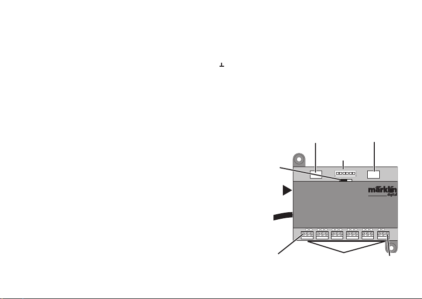
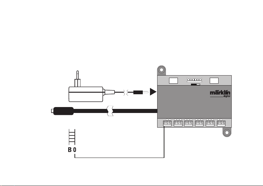
Konfiguration des L88
Nachdem der L88 angeschlossen wurde, meldet sich dieser
automatisch am Steuergerät an. Anschließend muss der L88
im Steuergerät konfiguriert werden.
• Mit der CS2 gehen Sie dazu auf Setup/Info. Schalten Sie
hier in den Konfigurationsmodus. Unter „Info“ können Sie
das Gerät auswählen, das Sie bearbeiten wollen. Wählen
Sie hier den neu eingesteckten L88
• Mit der CS3 gehen Sie über die Taste „System“ in die
Einstellungen. Nun finden Sie in der linken Spalte eine
Taste für den Link S88 (L88)
Folgende Einstellungen können / müssen vorgenommen
werden:
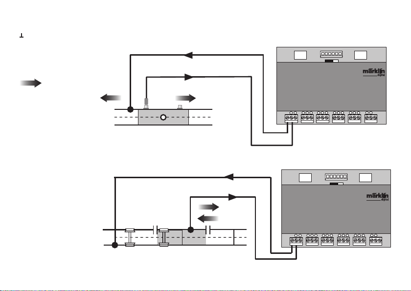
• Auswertung 1-16 (direkter Bus des L88),
Einstellung Einzeln = 16 Melde Kontakte (Standard)
Einstellung Matrix = bis zu 64 Taster
• Länge Bus 1-3
Hier muss eingetragen werden, wie viele S88 an jedem
einzelnen Bus angeschlossen sind (max. 31). Werte 0-31.
• Zykluszeit Bus 1-3
(Einträge müssen in der Regel nicht verändert werden!)
Abfragezyklen der S88 Busse in ms (min 10ms - max. 1000ms)
eintragen (werkseitig 100ms).
• Bitzeit S88
(Eintrag muss in der Regel nicht verändert werden!)
Einstellen Zyklus der Antwort (werkseitig 167µs)
• Zykluszeit (L88) Kontakt 1-16
(Eintrag muss in der Regel nicht verändert werden!)
Abfragezyklus der Link Kontakte bei Verwendung als Gleis-
kontakt 1-16.