Fenwal 35-63 Series User manual

SERIES 35-63
24 VAC Microprocessor Based
Intermittent Pilot Ignition Control
FEATURES
System diagnostic LED
Automatic reset 1 hour after lockout option
Safe Start and full time flame sensing
Remote flame sense option
Flame sense test pins
Custom prepurge and interpurge timings
Multiple trials for ignition
APPLICATIONS
Commercial cooking equipment
Commercial gas furnaces
Unit heaters
Water heaters
DESCRIPTION
The 35-63 is a 24 VAC intermittent pilot ignition control.
The microprocessor circuit design provides precise, repeatable
timing and operating sequences. The on-board diagnostics
with LED output provide assistance with troubleshooting to ensure
safe and efficient operation.
Agency Certifications
Component recognized system. Software conforms to UL
1998 requirements
Design certified to ANSI Z21.20, CAN/CSA C22.2
No. 199-M99
CE Approved to EN298 (Pending)
®
35.63.01
SPECIFICATIONS
Series 35-63, 24 VAC Intermittent Pilot Igntion Control Page 1
www.fenwalcontrols.com 1-800-FENWAL-1
Input Power Control: 18-30 VAC 50/60 Hz (Class 2 Transformer)
Input Current Drain 300 mA @24 VAC with gas and pilot relays energized
(Control only)
Main Gas Valve 2.0A max (continuous)
Pilot Gas Valve 2.0A max (continuous)
Operating Temperature -40ºF to +176ºF (-40ºC to +80ºC)
Storage Temperature -40ºF to +185ºF (-40ºC to +85ºC)
Flame Sensitivity 0.7 uA minimum
Flame Failure
Response Time 0.8 seconds maximum
Types of Gases Natural, LP, or manufactured
Spark Rate Line frequency (50/60 sparks/sec)
Size (LxWxH) 5.69 x 3.94 x 1.87 inches (with cover)
14.45 x 10.0 x 4.75 cm (with cover)
Weight 8 ounces (nominal) 224 grams (nominal)
Moisture Resistance
Conformal coated to operate non-condensing
to 95% R.H. Care must be taken to protect
module from direct exposure to water
Tries for Ignition One or three try versions available
Trial for Ignition
Periods 15, 30, 60, 90 seconds available
Prepurge Timings None, 15, 30 45 seconds available
Interpurge Timings None, 15, 30 seconds, or 4 minutes available

MOUNTING AND WIRING
CAUTIONS:
Label all wires prior to disconnection when servicing controls.
Wiring errors can cause improper and dangerous operation.
A functional checkout of a replacement control is recommended.
SEQUENCE OF OPERATION / FLAME
RECOVERY / SAFETY LOCKOUT
Start Up - Heat Mode
When a call for heat is received from the thermostat supplying 24 volts
to TH/W, the control will reset, perform a self check routine, flash the
diagnostic LED once in the first two seconds, and a pre-purge delay
begins. Following the pre-purge period, the pilot gas valve is energized
and sparks commence for the trial for ignition period. The main gas
valve is de-energized until the pilot flame is detected.
When the pilot flame is detected during the trial for ignition, the
sparking process is shutoff immediately and the main gas valve is
energized. The thermostat and pilot burner flame are constantly
monitored to assure the system continues to operate properly.
When the thermostat is satisfied and the demand for heat ends,
the pilot and main valves are de-energized immediately.
Failure to Light - Lockout
SINGLE TRIAL MODEL
Should the pilot burner fail to light or the pilot flame is not detected
during the trial for ignition period, the control will go into lockout.
The valves are de-energized immediately. The LED will indicate
the code for ignition lockout.
MULTI TRIAL MODEL
Should the pilot burner fail to light, or pilot flame is not detected
during the first trial for ignition period, the pilot and main gas
valves are de-energized. The control then goes through an
interpurge delay before another ignition attempt. The control will
attempt two additional ignition trials before going into lockout and
the valve relays will be de-energized immediately. Recovery from
lockout requires a manual reset by either resetting the thermostat
or removing 24 volts for a period of 5 seconds. On models with
automatic reset, if the thermostat is still calling for heat after one hour
the control will automatically reset and attempt to ignite the burner.
FLAME FAILURE- RE-IGNITION MODE
If the established pilot flame signal is lost while the burner is
operating, the control will respond within 1 second by de-energizing
the main gas valve and energizing the HV spark in an attempt to
relight the pilot burner for the programmed TFI period. If the pilot
burner does not light within the TFI, the pilot gas valve is
de-energized immediately and on multi-try models a new TFI
sequence begins. If the pilot burner does not relight, the control
will lockout as previously described in the "Failure to Light - Lockout"
section. Multi-try models will make 2 more attempts to light the
burner. If pilot flame is re-established, normal operation resumes.
FLAME FAILURE- RECYCLE MODE
The option "recycle after loss of flame" may be selected as a
special feature. With this option, upon loss of pilot flame, gas
valves are de-energized and the controller proceeds to interpurge
before attempting to relight the pilot flame. Multi-try models will
allow three tries for ignition including inter-purges. If pilot burner
relights, normal operation resumes, if pilot burner does not relight,
control will go into lockout as described in "failure to light".
TABLE 1 - FAULT CONDITIONS
LED INDICATION FAULT MODE
2 FlashesPilot flame without call for heat
3 Flashes Igntion Lockout
Steady On Internal Control Failure
Page 2 Series 35-63, 24 VAC Intermittent Pilot Ignition Control www.fenwalcontrols.com 1-800-FENWAL-1
The LED will flash on for 1/4 second, then off for 1/4 second
during a fault condition. The pause between fault codes is
3 seconds.
Internal Control Failure:
If the control detects an error in its software or hardware,
all outputs are turned off and the LED displays a steady
ON condition.
TERMINAL DESCRIPTION QUICK CONNECT
TH/W Thermostat Input 1/4 inch
PV1 Pilot Valve Power 3/16 inch
MV1 Main Valve Power 1/4 inch
V2 Valve Ground 3/16 inch
GND System Ground 3/16 inch
S1 Remote Flame Sensor (Optional) 1/4 inch
HV High Voltage Output 1/4 inch
WARNING:
Operation outside specifications could result in failure of the Fenwal
product and other equipment with injury to people and property
WARNING:
All wiring must be done in accordance with both local
and national electrical code.
WARNING:
The Series 35-63 uses voltages of shock hazard potential.
Wiring and initial operation must be done by a qualified
service technician.
The Series 35-63 is not position sensitive and can be
mounted vertically or horizontally. The case may be mounted
on any surface with #6 sheet metal screws.
TABLE 2 - WIRING TERMINALS
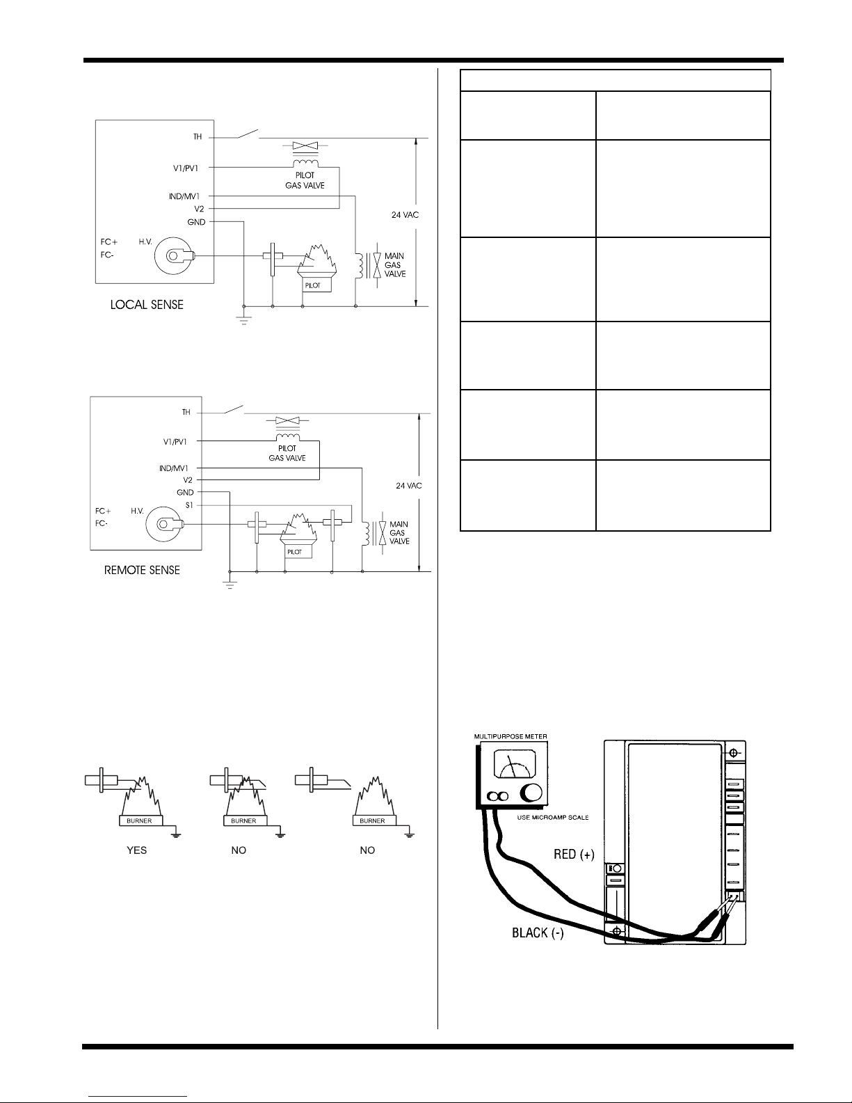
LOCAL SENSE
Figure 1
Series 35-63, 24 VAC Intermittent Pilot Ignition Control Page 3
www.fenwalcontrols.com 1-800-FENWAL-1
REMOTE SENSE
Figure 2
Proper Electrode Location
Proper location of the electrode assembly is important for optimum
system performance. It is recommended that electrode assembly
be mounted temporarily using clamps or other suitable means
so that the system can be checked before permanently mounting
the assembly. The electrode assembly should be located so that
the tips are inside the flame envelope and about 1/2 inch (1 cm)
above the base of the flame. See Figure 3 below.
SYMPTOM RECOMMENDED
ACTIONS
1. Control does not start A. Miswired
B. 24 VAC Transformer bad
C. Fuse/Circuit breaker bad
D. Bad control, check
LED for steady on or
flashing code (see Table 1)
2. Thermostat on - no spark A. Miswired
B. Bad thermostat, no voltage
at thermostat terminal W
C. Bad control, check LED
for steady on or flashing codes
3. Valve on - no spark
during TFI
A. Shorted electrode - establish
1/8th inch gap
B. Check high voltage cable
C. Miswired
4. Spark on - valve off A. Valve coil open
B. Valve wire disconnected
C. Bad control, check voltage at
gas valve terminals PV1 or MV1
and V2
5. Flame okay during TFI -
no flame sense after TFI A. Check electrode position
B. Check high voltage wire
C. Poor ground at burner
D. Poor flame, check flame current
Flame Sensor Current Check
Flame current is the current that passes through the flame
from the sensor to ground. The minimum flame current
necessary to keep the system from lockout is 0.7 micro
amps. To measure flame current, connect analog DC micro-
ammeter to the FC-, FC+ terminals per figure. Meter should
read 0.7 microamps or higher. If the meter reads below "0"
on scale, meter leads are reversed. Disconnect power and
reconnect meter leads for proper polarity.
CAUTIONS:
1. Ceramic insulators should not be in or close to the flame.
2. Electrode assemblies should not be adjusted or disassembled.
Electrodes should have a gap spacing of 0.125± 0.031 in
(3.12± 0.81 mm), unless otherwise specified by the appliance
manufacturer. If this spacing is not correct, the assembly must be
replaced. Electrodes are NOT field adjustable.
3. Exceeding the temperature limits can cause nuisance lockouts
and premature electrode failure.
4. Electrodes must be placed where they could not be exposed
to the appliance user in normal operation.
Figure 4
Figure 3
TABLE 3 - TROUBLESHOOTING GUIDE
/w
/w
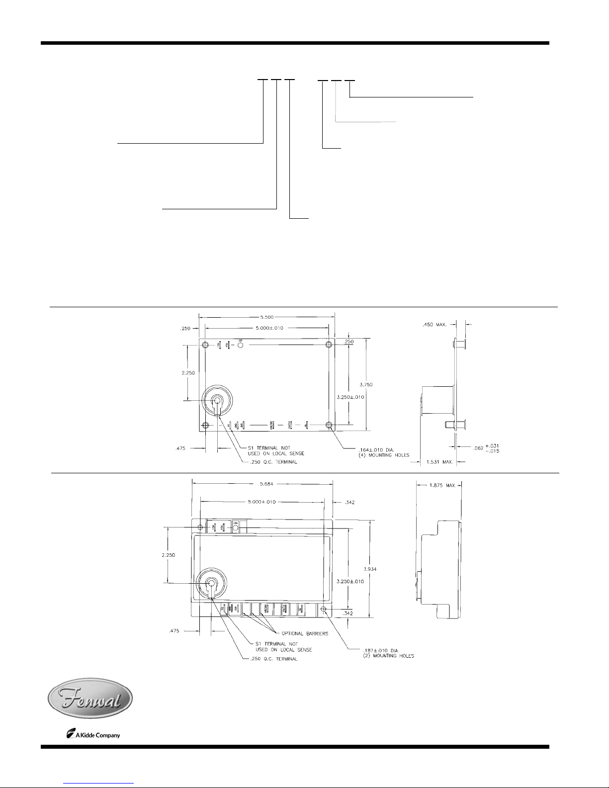
DIMENSIONS
FENWAL
400 MAIN STREET, ASHLAND, MA 01721
TEL: (508) 881-2000 FAX: (508) 881-6729
www.fenwalcontrols.com
© 2005 Fenwal Printed in U.S.A. TAG
These instructions do not purport to cover all the details or variations in the equipment
described, nor do they provide for every possible contingency to be met in connection with
installation, operation and maintenance. All specifications subject to change without notice.
Should further information be desired or should particular problems arise which are not covered
sufficiently for the purchaser’s purposes, the matter should be referred to KIDDE-FENWAL,
Inc., Ashland, Massachusetts.
P/N 35.63.01 3/21/05
®
Page 4 Series 35-63, 24 VAC Intermittent Pilot Ignition Control www.fenwalcontrols.com 1-800-FENWAL-1
CONTROL CONFIGURATION
Enclosure Configurations
and Wiring Options
0 = Noryl Gray Enclosure
1 = Integral Standoffs
2 = Board Only
Trial for Ignition
Time (TFI)
1 = 15 seconds
3 = 30 seconds
5 = 60 seconds
7 = 90 seconds
Inter-Purge
Time
0 = None (Single Try
Models Only)
1 = 15 seconds
2 = 30 seconds
3 = 45 seconds
4 = 4 minutes
Number of Ignition Trials,
Flame Sense Method and Lock Out Reset Method
0 = Single Try, Local Sense Thermostat / power off reset
1 = Single Try, Remote Sense Thermostat / power off reset
2 = Single Try, Local Sense Automatic Reset
3 = Single Try, Remote Sense Automatic Reset
5 = Three Tries, Local Sense Thermostat / power off reset
6 = Three Tries, Remote Sense Thermostat / power off reset
7 = Three Tries, Local Sense Automatic Reset
8 = Three Tries, Remote Sense Automatic Reset
XXX
35 - 63 0 - X X X
Pre-Purge
Time
0 = None
1 = 15 seconds
2 = 30 seconds
3 = 45 seconds
4 = 4 minutes
Options
1 = Recycle after Loss of Flame
5 = Re-ignition after Loss of Flame
9 = Special OEM Configuration
Figure 5:
Uncovered
with standoffs
Figure 6:
With cover
Table of contents
Other Fenwal Control Unit manuals


Popular Control Unit manuals by other brands


Pepperl+Fuchs
Pepperl+Fuchs ICA-8DIO4M1-G20-IO manual

TLV
TLV CV-COS-16 instruction manual

VDO
VDO CI 3000 - COMPATIBILITY LIST Mounting instruction

M-system
M-system Mini-M M2ADS instruction manual

RF SOLUTIONS
RF SOLUTIONS BRAVO-T868 quick start guide

GE
GE SX TRANSISTOR CONTROL IC3645SR4U404N2 Installation and operation manual