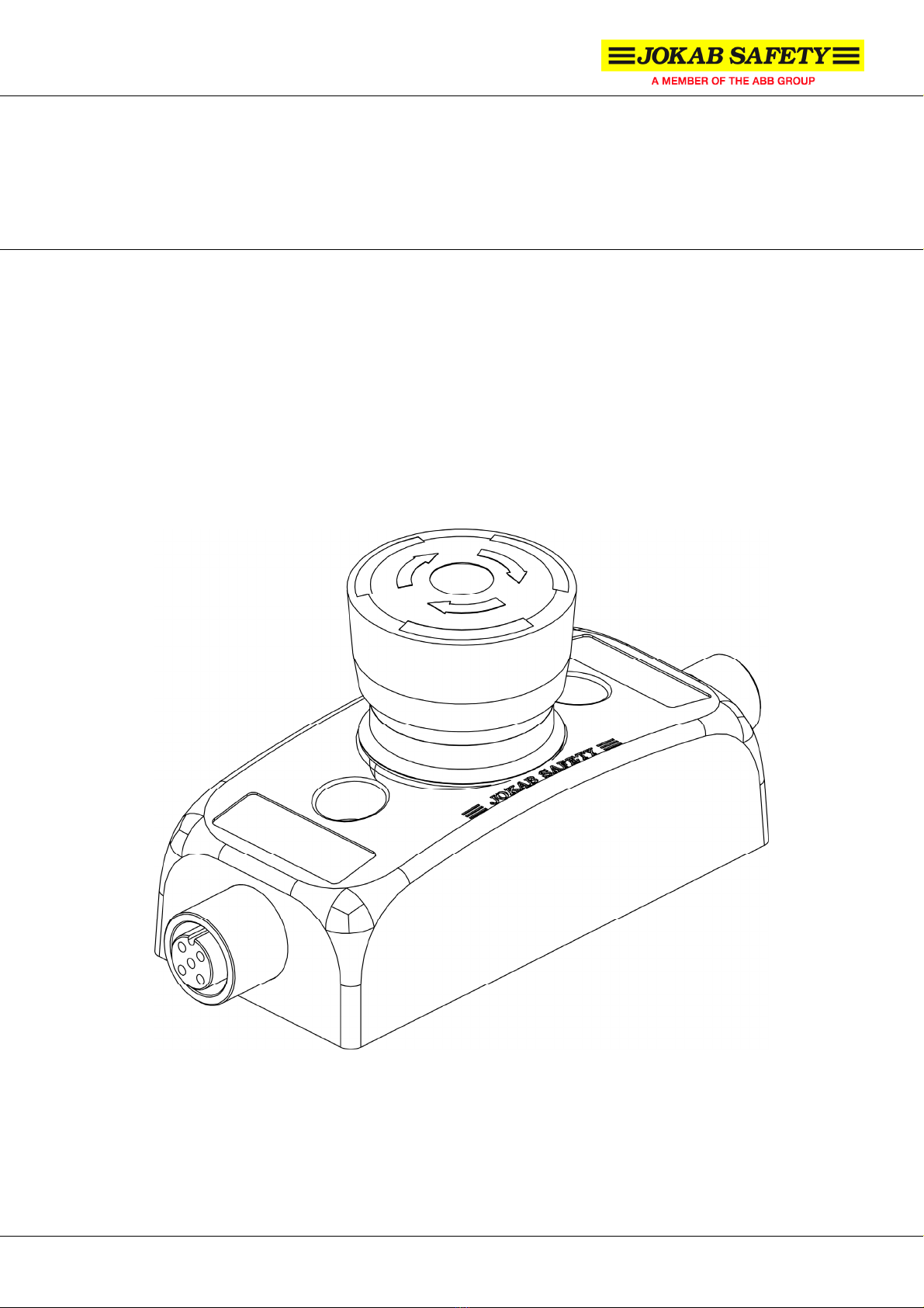
ABB jokab safety Smile Tina Series User manual

Jokab Safety AB Varlabergsvägen 11, S-434 39, Sweden
www.jokabsafety.com
Original instructions
Smile Tina
Emergency stop with indication

Smile_Tina_Manual_(English)_v1A www.jokabsafety.com
2010-10-19
2
Table of Contents
1Introduction.............................................................................................................................. 3
Scope .................................................................................................................................................. 3
Audience ............................................................................................................................................. 3
Prerequisites ....................................................................................................................................... 3
Special notes....................................................................................................................................... 3
2Overview................................................................................................................................... 4
General description ............................................................................................................................. 4
Safety regulations ............................................................................................................................... 4
3Connections............................................................................................................................. 5
Connection examples.......................................................................................................................... 5
4Installation and maintenance ................................................................................................. 7
Installation precautions ....................................................................................................................... 7
Maintenance........................................................................................................................................ 7
Testing of the safety functions ............................................................................................................ 7
Troubleshooting .................................................................................................................................. 7
5Operation.................................................................................................................................. 8
LED indication ..................................................................................................................................... 8
Information output signal attributes..................................................................................................... 8
6Model overview........................................................................................................................ 9
7Technical data........................................................................................................................ 10
Dimensions........................................................................................................................................ 11
8EC Declaration of conformity ............................................................................................... 12

Smile_Tina_Manual_(English)_v1A www.jokabsafety.com
2010-10-19
3
1 Introduction
Scope
The purpose of these instructions is to describe the emergency stop Smile Tina and to provide the
necessary information required for installation and operation.
Audience
This document is intended for authorized installation personnel.
Prerequisites
It is assumed that the reader of this document has knowledge of the following:
•Basic knowledge of Jokab Safety products.
•Knowledge of machine safety.
Special notes
Pay attention to the following special notes in the document:
Warning!
Danger of severe personal injury!
An instruction or procedure which, if not carried out correctly, may result in
injury to the technician or other personnel.
Caution!
Danger of damage to the equipment!
An instruction or procedure which, if not carried out correctly, may damage the
equipment.
NB: Notes are used to provide important or explanatory information.

Smile_Tina_Manual_(English)_v1A www.jokabsafety.com
2010-10-19
4
2 Overview
General description
In order to fulfil the need for a small and easy to install E-stop, Smile Tina has been developed. The
size of the device makes it possible to be installed wherever needed. With M12 connections or cable
and centralized mounting holes. Smile Tina is very easy to install, especially on aluminium extrusions.
There are three different versions available, either with one or two M12 connections or cable. Two
M12 connectors are used to enable the connection of E-stops in series, which is often used with
dynamic safety circuits fulfilling safety category 4. On the top of the Smile Tina E-stop unit, an LED
indicates the actual status according to the dynamic system. Smile Tina is intended for use in safety
circuits in accordance with EN 60204-1.
Safety regulations
Warning!
Carefully read through this entire manual before using the device.
The devices shall be installed by a trained electrician following the Safety regulations, Standards and
the Machine directive.
Failure to comply with instructions, operation that is not in accordance with the use prescribed in these
instructions, improper installation or handling of the device can affect the safety of people and the
plant.
For installation and prescribed use of the product, the special notes in the instructions must be
carefully observed and the technical standards relevant to the application must be considered.
In case of failure to comply with the instructions or standards, especially when tampering with and/or
modifying the product, any liability is excluded.

Smile_Tina_Manual_(English)_v1A www.jokabsafety.com
2010-10-19
5
3 Connections
NB: Shielded cable is recommended between this unit and the rest of the safety circuits.
Warning! The information channel output shall never be used for the safety purpose(s).
Connection examples
Connection example – Three Smile 12EA Tina connected in series to Vital control device or Pluto safety PLC
M12 5-pole female seen
from cable side
M12 5-pole male seen
from cable side
Smile 10EA Tina
5-pole wired:
(1) Brown: +24 VDC
(2) White: Dynamic signal input
(3) Blue: 0 VDC
(4) Black: Dynamic signal output
(5) Grey: Information
Smile 11EA Tina
M12 5-pole male:
(1) Brown: +24 VDC
(2) White: Dynamic signal input
(3) Blue: 0 VDC
(4) Black: Dynamic signal output
(5) Grey: Information
Smile 12EA Tina
M12 5-pole male (input):
(1) Brown: +24 VDC
(2) White: Dynamic signal input
(3) Blue: 0 VDC
(4) Black: -
(5) Grey: -
M12 5-pole female (output):
(1) Brown: +24 VDC
(2) White: Dynamic signal output
(3) Blue: 0 VDC
(4) Black: -
(5) Grey: Information

Smile_Tina_Manual_(English)_v1A www.jokabsafety.com
2010-10-19
6
More connection examples can be found at www.jokabsafety.com or in the Safety Handbook.
Connection example – Three Smile 11EA Tina and one Eden connected in series to Vital control device or Pluto safety
PLC through the connection block Tina 4A
Connection example – Three Smile 11EA Tina connected in series to Vital control device or Pluto safety PLC through
connection terminals in the electrical cabinet

Smile_Tina_Manual_(English)_v1A www.jokabsafety.com
2010-10-19
7
4 Installation and maintenance
Installation precautions
First mount Smile Tina to the surface with two M5 bolts, and then attach the M12 connection(s).
Warning! All the safety functions must be tested before starting up the system.
Maintenance
Warning! The safety functions and the mechanics shall be tested regularly, at least once every year
to confirm that all the safety functions are working properly (EN 62061:2005).
Warning! In case of breakdown or damage to the product, contact Jokab Safety. Do not try to repair
the product since it may accidentally cause permanent damage, impairing the safety of the device
which in turn could lead to serious injury to personnel.
Testing of the safety functions
Make sure the safety unit is working properly by following these steps:
•Interrupt the dynamic safety circuit before this unit. The LED should flash between green and
red.
•Interrupt protection (i.e. push the E-stop button). The LED should light red.
•The LED should light green when protection is OK and the safety circuit is not previously
broken.
Troubleshooting
LED indicator note Expected causes of faults Checking and measures to take
E-stop button is down Reset the button by turning it
clockwise and pulling it upward.
Lights red 24 VDC input to pin-2 (no
dynamic signal)
Check if there is 24 VDC to input (pin-
2). If Yes, check cable or unit before
and fix it.
No lights Loss of power supply Check 24 VDC / 0 VDC power supply
Lights green (but no dynamic
output detected)
Defected dynamic signal
input to unit (asymmetric
pulses)
Check the dynamic input or the unit
before
Weak lights or red and green
lights at the same time The unit is defect The unit needs to be replaced.
Contact Jokab Safety.
NB: Tina 1A can be used instead of this unit to check if the safety circuit is OK (only for test).
Warning! Replace a defected unit with a new one and never bypass the safety circuit using Tina 1A
or any other solution.

Smile_Tina_Manual_(English)_v1A www.jokabsafety.com
2010-10-19
8
5 Operation
LED indication
LED Indication Description Input signal on pin-2
Green Safety circuit closed
(protection OK) Dynamic signal in
Green-Red (flash) Safety circuit open
(protection OK) No dynamic signal in or 0 VDC in
LED on Tina
Red Safety circuit interrupted
(protection open)
+24 VDC in or safety circuit
interrupted
Information output signal attributes
The information output of the unit (pin-5) is set either high (+24 VDC) or low (0 VDC) depending on
four different input signals (pin-2):
•Dynamic signal - Dynamic signal input exist, i.e. the safety circuit is OK up until this unit
•No dynamic signal - Dynamic signal input does not exist, i.e. the safety circuit is interrupted
before this unit.
•+24 VDC - A constant +24 VDC signal is applied = high (H)
•0 VDC - The pin is connected to 0 VDC = low (L)
The information output signal depends on the input signal according to the table below. Note that if the
safety is interrupted; i.e. if the emergency button is pressed, the information output signal is always
low (L).
Input signal (pin-2) Dynamic signal No dynamic signal +24 VDC 0 VDC
Info output signal (pin-5) High High Low High
The delay for switching the information signal output from high to low (H ÆL) and low to high (L ÆH)
is given in the table below.
Info output signal switch H ÆL L ÆH
Delay ~ 12 ms ~ 0 ms
NB: If the unit detects an error (short circuit or interruption) lasting shorter than 13 ms the information
output signal is set to low for 1.2 s (1200 ms) and then set to high again. This does not affect Vital
since it needs 22 ms to release. Pluto however does release, which means that a filter (20 ms) must
be implemented if this function is needed.
Warning! The information output signal is not a failsafe signal and should never be used for the
safety purpose(s).

Smile_Tina_Manual_(English)_v1A www.jokabsafety.com
2010-10-19
9
6 Model overview
Type Article number Description
Smile 11EA Tina 30-050-00 E-stop, red button, M12 5-pole male
Smile 11EAR Tina 30-050-01 E-stop, red button, M12 5-pole male, reversed
Smile 12EA Tina 30-050-02 E-stop, red button, M12 5-pole male, M12 5-pole female
Smile 12EAR Tina 30-050-03 E-stop, red button, M12 5-pole male, M12 5-pole female,
reversed
Smile 10EA Tina 30-050-04 E-stop, red button, 1m integrated cable
Smile 11SA Tina 30-050-05 E-stop, black button, M12 5-pole male
Smile 12SA Tina 30-050-06 E-stop, black button, M12 5-pole male, M12 5-pole female
Smile 11SAR Tina 30-050-07 E-stop, black button, M12 5-pole male, reversed
Smile 12SAR Tina 30-050-08 E-stop, black button, M12 5-pole male, M12 5-pole
female, reversed
Smile 10EA Tina
Smile 11EAR Tina Smile 12EAR Tina
Smile 11EA Tina Smile 12EA Tina

Smile_Tina_Manual_(English)_v1A www.jokabsafety.com
2010-10-19
10
7 Technical data
Manufacturer
Address JOKAB SAFETY AB
Varlabergsvägen 11
S-434 91 Kungsbacka
Sweden
Power supply
Operating voltage 24 VDC +15 %, -25 %
Total current consumption 47 mA (57 mA with max information output)
Information output: Max 10 mA
Time delay t (in/out) t < 70 µs
Voltage supply at normal operation
(protection OK) and 24 VDC supply
voltage
Dynamic input: between 9 and 13 volt (RMS)
Dynamic output: between 9 and 13 volt (RMS)
Information output: ~ 23 VDC
General
Protection class IP65
Ambient temperature Storage: -30…+70°C
Operation: -10…+55°C
Humidity range 35 to 85 % (with no icing or condensation)
Housing material Polyamide PA66, Macromelt, polybutylenterephthalate PBT,
Polypropene PP, UL 94 V0
Connectors Smile 10EA Tina: 5-pole cable, 1 m (Smile 10EA Tina)
Smile 11x* Tina: M12 5-pole male
Smile 12x* Tina: M12 5-pole male, M12 5-pole female
* - x can be all models -EA, -EAR, -SA, -SAR
Size 84 x 40 x 52 (L x W x H) – see drawing
Weight ~ 65 g
Colour Yellow base, red or black button
Actuator force (E-stop button) 22 +/- 4N
Actuator travel ~ 4 mm to latch
Mechanical life > 50,000 operations
Impact resistance (half sinusoidal) Max. 150 m/s2, pulse width 11 ms, 3-axis
(as per EN IEC 60068-2-27)
Vibration resistance (half sinusoidal) Max. 50m/s2at 10 Hz, 10 cycles, 3-axis
(as per EN IEC 60068-2-6)
Safety / Harmonized Standards
Approved standards European Machinery Directive 2006/42/EC
EN ISO 12100-1:2003, EN ISO 12100-2:2003,
EN 60204-1:2007, EN 954-1:1996, EN ISO 13849-1:2008,
EN 62061:2005, IEC 60947-5-1:2003 + A1:2009
IEC/EN 61508-1…7 SIL3, PFHd: 4.66*10-9
EN 62061 SIL3
EN ISO 13849-1 Performance level: Pl e, category 4
EN 954-1 Category 4
Certificates TÜV Nord

Smile_Tina_Manual_(English)_v1A www.jokabsafety.com
2010-10-19
11
Dimensions

Smile_Tina_Manual_(English)_v1A www.jokabsafety.com
2010-10-19
12
8 EC Declaration of conformity
EC Declaration of conformity
(according to 2006/42/EC, Annex2A)
We JOKAB SAFETY AB
Boplatsgatan 3
SE-213 76 Malmö
Sweden
declare that the safety components of JOKAB SAFETY make with type designations
and safety functions as listed below, is in conformity with the Directives
2006/42/EC
2006/95/EC
2004/108/EC
Person authorised to compile
the technical file
Torgny Olsson
JOKAB Safety AB
Boplatsgatan 3
SE-213 76 Malmö
Sweden
Product EC type-examination
certificate/Notified Body
Serial number
Safety module
Vital1
44 205 09 372092-001/0044 [000 – 000 ... 999-999]
Non-contact safety sensor
Eden (Adam , Eva) E/C/EC
44 205 09 372092-002/0044 [000 – 000 ... 999-999]
Adapter unit
Tina 1-8, Tina 10-12
44 205 09 372092-002/0044 [000 – 000 ... 999-999]
Emergency stop device
Smile Tina
44 205 09 372092-002/0044 [000 – 000 ... 999-999]
Emergency stop device
Inca-Tina
44 205 09 372092-002/0044 [000 – 000 ... 999-999]
Muting unit
FMC-Tina
44 205 09 372092-002/0044 [000 – 000 ... 999-999]
Non-contact safety sensor
including locking function
Magne 2A, 2B, 2AX, 2BX
44 205 09 372092-002/0044 [000 – 000 ... 999-999]
Light beam
Spot 10, 35
44 205 09 372092-002/0044 [000 – 000 ... 999-999]
Adapter unit
Tina 8 Profibus
05-SKM-CM-0138/0409 [000 – 000 ... 999-999]
Sensor expansion unit
Tina Duo 1, Tina Duo 2
05-SKM-CM-0138/0409 [000 – 000 ... 999-999]
EC type-examination TÜV NORD CERT GmbH
Langemarckstrasse 20,
45141 Essen
Germany
Notified body No. 0044
Inspecta Sweden AB
Box 30100
SE-104 25 Stockholm
Sweden
Notified body No. 0409
Used harmonized standards EN ISO 12100-1,-2, EN 954-1, EN ISO 13849-1, EN 62061, EN 60204-1,
EN 61496-1, IEC 60664-1, EN 61000-6-2, EN 61000-6-4, EN 60947-5-1, EN 1088
Torgny Olsson
Vice MD
Malmö 2009-12-15
Mats Linger
MD
Kungsbacka 2009-12-15
JOKAB SAFETY AB Varlabergsvägen 11, S-434 39 Kungsbacka, Sweden
www.jokabsafety.com
This manual suits for next models
20
Table of contents
Other ABB Control Unit manuals

ABB
ABB RED615 ANSI Instructions for use

ABB
ABB ACQ580-04 User manual

ABB
ABB Foundation LD 810HSE Ex User manual

ABB
ABB OMD800 User guide

ABB
ABB REF542plus Guide

ABB
ABB FENA-21 Installation manual

ABB
ABB ACSM1 Series User manual

ABB
ABB UCU-22 User manual

ABB
ABB RDIO-01 User manual

ABB
ABB ACQ580-34 User manual

ABB
ABB MTAC-01 User manual

ABB
ABB FCAN-01 Installation manual

ABB
ABB COM600 series 5.0 Product manual

ABB
ABB FSO-21 User manual

ABB
ABB Triguard SC300E User manual

ABB
ABB relion REF615 User manual

ABB
ABB 650 series Instructions for use

ABB
ABB AC500 PLC User manual

ABB
ABB ACS880 Series Owner's manual

ABB
ABB TruONE Ekip User manual