Soham Impex 200 User manual
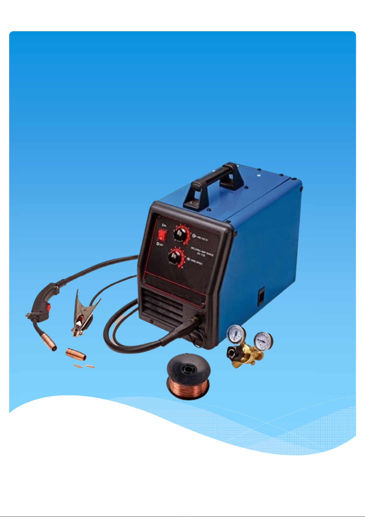
GMAW WELDING MACHINE
MANUAL
Vavdi Survey no. 28, Shivam Industrial Area, Street No.3 Plot No.7, Near Sunny Raj Metal,

USER MANUAL
GMAW WELDING
MACHINE

Safety notices
For the sake of your and other's safety, please read the manual
carefully before installation or operation of the equipment!
The people operating the equipment or nearby should fully know about
safety measures. The safety will be fulfilled through everyone's common
effort.
The complete equipment should be securely grounded.
All operations must be performed:
In accordance with the operating instructions
By the special operator
Incorrect operation is likely to cause an accident. injure the operator,
and damage the equipment.
When operating the equipment, every operator must know about:
Control of the equipment
Operation of the equipment
All effective safety rules
For its convenient use, every selection switch, knob, button, ampere
meter, and voltmeter is marked. Its function and usage are described
clearly.
Safety information:
Be sure to use appropriate personal safety outfit, for example,
protective goggle, mask, and gloves. Do not wear a tie, bracelet, and loose
clothing that are easy to twine the equipment.
Put the fire extinguishers in the specially marked position (the fire
extinguishers shall be provided by the user).
Keep the arc-welding rectifier a certain distance away from flammable
substances such as waste oil and clothing.
The splashing can cause a fire and burn your skin. The arc light would
damage your eyes and skin.
Smoke and dust produced during the welding process are harmful to
your body. Please try to remove them or avoid inhaling them.
Check the emergency and safety devices every day.
Be sure to cut the power off after finfish your work and/or when leave
the welding site temporarily.
Be sure to check the arc-welding rectifier before and after use of it. Be
sure to find out the reason and correct the abnormality when any
abnormality occurs. Do not use the equipment before correct the
abnormality.
Be sure to cut the power off before check the welder. Do not open the
case before cut the power off to avoid an electric shock.

1. Main purposes and features
1.1 Main purposes
IGBT inverter gas-shielded welders of GMAW/MIG series include Model
200, 300, and 400. They are mainly applicable to CO2-shielded welding,
consumable electrode argon arc-welding (GMAW/MIG), and mixed gas-
shielded welding (GMAW/MAG). They conform to safety requirements
of arc-welding equipment technical requirements of the welder
The model description of the series conforms to standards of model
description for the arc welder.
1.2 Features
IGBT high frequency inverter technology is used. Up to 20KHz inverter
frequency provides fast dynamic response.
Use of current control mode provides high quality and reliable
performance.
Total digital presetting and display of welding current/voltage provides a
visual and convenient operation.
Current self-adaptation within 30mm dry extension is applicable to all-
position welding.
Perfect protection circuit and fault display function provides safety,
reliability, and convenience to locate a fault.
Metal transfer waveform control provides stable electric arc, little
splashing, and well-shaped welding lines.
Arc-striking and ball removal circuit is added to guarantee the arc-
striking success rate.
Small dimension, low weight, high efficiency, energy saving, high duty
cycle, and no noise
Reasonable structure and concise layout provides convenient
maintenance.
Applicable to CO2 /MIG/MAG welding with solid/flux-cored welding
wire of different welding specifications
Stable welding process and strong immunity against power grid
fluctuation ( 280~480V)

2. Normal operating conditions
Environmental temperature
-10°C ~ 40°C
Elevation
≤1000 meters
Relative humidity
At 40°C: relative humidity ≤50%
At 20°C: relative humidity ≤90%
Power requirements
Power supply: three-phase, 415V, 50Hz
Imbalance rate of
the
three-phase voltage : <±0.5%
Voltage fluctuation of the power grid : <±10%
Frequency fluctuation : <±1%
Others
In the working site, there are no gas, vapor, chemical sediment,
dust, dirt, mildew, and other flammable/corrosive substance, which
severely affect the use of the arc-welding rectifier. In addition, avoid
violent shake and jolt of it.
Put the equipment in a dry and ventilated place. Avoid direct
exposure to sunlight and rain.

Technical Specification
GMAW WELDING MACHINE 300AMP MOSFET BASED
Type of power Source
MOSFET based
Current capacity of GMAW welding set
300MM
Current rating at 40 % Duty Cycle
340MM
Current rating at 100 % Duty Cycle
210MM
Welding current range
300AMP
Power Input
Single Phase (215 ± 15% V AC, 1 Phase, 50 Hz)
Open circuit voltage, DC
80 VOLT
Type of Metal which can be welded
Mild Steel
Open Circuit Power
5WATT
Protection Class
IP23
Di�erent type of insulation class
F
Type of cooling
Forced air cooling
Type of Wire feeder drive
2 roll drive
Wire Feeding rate
18
Type of welding Torch
WELDING TORCH

4. Hoist and storage
There are two handles on the top of the arc-welding rectifier for
hoisting purpose.
The arc-welding rectifier and wire feeder are packed with the carton.
It can be transferred manually or with a forklift. However, be sure to
avoid its hit or fall.
The arc-welding rectifier and wire feeder should he stored in a dry,
ventilated, and rainproof place. The storage temperature is -25~ 55'C.
5. Installation and attention
First, please read the user's manual carefully. Check if the
product and accessories are complete and in good condition.
Put the arc-welding rectifier in a dry, dustproof, rainproof, and
anticorrosive place. Make the installation and connection in the
following ways (refer to Diagram 2). Put the arc-welding rectifier in a
well-ventilated environment to facilitate heat dissipation. Air outlet opening
should be not less than 800mm away from the wall, and not less than 100mm
away from the right and left wall.
The three-phase power cable must go to the arc-welding rectifier through the
air switch. Select the capacity of the air switch in accordance with technical
parameter requirements of the welder.
Attention:
The case of the arc-welding rectifier must be securely grounded
(in the place with a grounding mark) to avoid an electric shock.
The arc-welding rectifier must be securely connected to the three-
phase power cable. Otherwise, the equipment would function improperly,
or the local area of the joint be heated and damaged.
It is strictly prohibited to pull the air switch when the load is
applied to avoid the damage.
The "+" output of the arc-welding rectifier should be connected to the wire-
feeder, and the "-" output to the to-be-welded workpiece.
One end of the gas hose is connected to the gas outlet opening of the gas
adjuster, and the other end to the inlet opening of the gas valve of the
wire feeder.

6. Function description
Function description of the front/rear panel of the arc-welding rectifier
No.
Name
Description
1
Amperemeter
Preset and display the output current of the
welder
2
Voltmeter
Preset and display the output voltage of the
welder
3
Power indicator light
Indicate if the power supply of the welder is
turned on/off.
4
Abnormality indicator light
The abnormality indicator light is on when
an abnormality occurs
5
Adjustment knob of
arc-receiving current
Set the arc-receiving/manual welding current
6
Adjustment knob of arc-receiving
voltage
Set the arc-receiving voltage for welding
7
Arc-receiving On/Off switch
Make sure if the arc-receiving specification is
required
8
Gas check switch
Check gas flow and pre-adjust gas flow rate
9
Wire-selection switch
Select the welding-wire diameter
10
Function switch
Select manual/gas-shielded welding
11
Plug of the control cable
Connected to the control cable of the wire
feeder
12
Output anode
Connected to the welding power cable of the
wire feeder
13
Output cathode
Connected to the workpiece
14
Input terminal box
Connected to the input power cable of three-
phase, 415V/AC, and 50Hz
15
Plug of the heater
Connected to the heater of the CO2 adjuster
16
Control power fuse
Protect the control circuit
17
Air switch
When the welder functions improperly, or is
overloaded for a long time, protection
function of the air switch is activated.
18
Nameplate
Indicate the related technical parameters and
information of the welder
19
Grounding terminal
Be sure to connect it to the welding ground
when use the welder to ensure safe use of
electricity.

7. Use and operation
7.1 Preparation before use
Connect the input power cable of the welder to the power grid according
to the requirements. (Refer to 5. Installation and attention)
Attention: The three relatively thick wires are connected respectively to the
phase wire of the three-phase power supply. Do not need to identify the phase
sequence. The relatively thin wire is connected to the welding ground. The
connection must be secure. Be sure not to make any wrong connection.
Otherwise, the equipment would be damaged and human safety be
endangered.
The air switch on the rear panel of the welder is put in closed state ("On"
position), and the power switch in the power board is put in opened state
("Off" position).
Attention: The air switch should be normally closed. When the load is
applied, it is strictly prohibited to pull it to avoid the damage.
Check if the circuit connection is correct and secure and the power
supply of the power grid meets the requirements. Turn on the power switch in
the power board after make sure all connections are correct.
Attention: At this time, the fan runs and the power indicator light is on.
The preset voltage and current value (a minus value) is displayed in the
voltmeter and arnperemeter.
Put the "Gas check" switch to the "Gas check" position and adjust the gas
flow rate. Then, put the "Gas check" switch to the "Welding" position.
Load the wire with the "Inching" button on the operating panel of the wire
feeder.
Attention: The width of the wire groove of the wire-feeding reel should
match with the diameter of the used welding wire. The pressure of the
wire-pressing roller should be adjusted to be just appropriate to dispense
the welding wire.
Attention: The aperture of the contact tip of the welding gun and the wire-
feeding hose should match with the diameter of the used welding wire.
Put the "Wire-selection" switch of the welding power panel to a correct
position, which is the one to match the diameter of the welding wire.

Attention: If the "Wire-selection" switch is put to a incorrect position,
the welding current will not match with the preset value.
The "Function" switch position is incorrect.
When the contact tip is burned or in a poor contact, it is
necessary to replace it to avoid affecting the welding stability.
When the diverter or nozzle of the welding gun is damaged, it is
necessary to replace it to avoid affecting the gas shielding effect.
When the wire-feeding hose of the welding gun is blocked, it is
necessary to replace or clean it to avoid affecting the welding stability.
7.2 Welding
When perform the gas-shielded welding, turn the adjustment knob of
the welding voltage and current to the desired value according to process
requirement (The minus value displayed in the ampere meter and voltmeter
is the present value, and the plus value is the actual output value. The
preset voltage value is actual output value and the preset current value is
percent of the wire-feeding speed. The maximum value is 100%).
When the arc-receiving specification is required, it is necessary to
put the "Arc-receiving On/Off" switch in the welding power panel to the
"On" position, and turn the adjustment knob of the arc-receiving voltage and
current to the desired value.
Attention: When the "Arc-receiving On/Off' switch is put to the "Off"
position, press and hold the switch of the welding gun to start the
welding, and release it to stop the welding.
When the "Arc-receiving On/Off' switch is put to the "On"
position, press the switch of the welding gun to start the welding. Press
the switch again and hold it to enter arc-receiving state, and release it
to stop the welding.
When make sure the arc-welding rectifier can function properly after
adjustment, you can use and operate the welder according to your desired
welding process requirements and methods.
When perform the manual welding, turn the arc-receiving current knob in
the welder panel to preset the output current. The actual output current is
the maximum output current of the welder multiplied by your preset
percent.
7.3 Shutdown
When complete the welding and need to turn the welder off, put
the power switch in the power board to the "Off" position.

8. Maintenance and troubleshooting
8.1 Maintenance
After the arc-welding rectifier is used for a period of time, it is necessary to
remove dust and dirt in the equipment with the dry compressed air or in
other way to ensure the arc-welding rectifier functions properly for a long
time, and prolong its service life.
Check the fasteners and connections in the equipment to see if any is loose
or broken. If yes, it is necessary to correct it in time.
Attention:
* Be sure to cut off the power supply of the arc-welding rectifier
when remove dust and dirt.
* Do not fiddle with the connections in the equipment
when
remove dust and dirt to avoid damaging the component.
Check the grounding of the case of the arc-welding rectifier at all times to
avoid an electric shock.
Check if the arc-welding rectifier is securely connected with the three-
phase power supply of the power grid at all times to avoid the arc-welding
rectifier functioning improperly or the local area of the joint being heated
and damaged.
Check if the external bolts of the arc-welding rectifier is secured at all times
to avoid the arc-welding rectifier functioning improperly or the local area of
the joint being heated and damaged.
Clean the wire feeder at all times to keep it clean and well insulated.
Make sure no foreign substance exists in the wire groove of the wire-feeding
reel to ensure smooth wire feeding.
Clean the wire-feeding hose of the welding gun at all times to ensure its
smoothness and intactness.
8.2 Troubleshooting
8.2.1 Make the following checks first when the arc-welding rectifier functions
improperly:
Is the three-phase supply voltage between 340V~420V?
Does the three-phase power supply have a phase lacking fault?
Is the input power cable of the arc-welding rectifier securely connected?
Is the output power cable of the arc-welding rectifier correctly connected
and in a good contact?
Is any component burned, or any connection broken or loose in the
equipment?

Table 3: Troubleshooting
No.
Trouble
Reason
Remedy
1
The power indicator
light is not on and the
fan doesn't run. There
is no display in the
voltmeter and
amperemeter.
The external power
supply has a phase-
lacking fault
Check the three-
phase power
supply circuit
The automatic air
switch is unclosed or
damaged
Close the
automatic air
switch or replace
it
The input connection
is
broken
Check the
connection or
replace the
damaged part
The control
transformer is
damaged
Replace the
transformer
2
The fan doesn't run
The fan or the fan
capacitor is damaged,
or the related
connection has a fault
Replace the
damaged part, or
check the
connection
3
The protection
indicator light is not
on and the welder
doesn't work
The control board has
a fault. The part is
damaged
Please contact
with our
company
The voltage of the
power grid is too high.
The arc-welding
rectifier is in automatic
protection state.
It will resume
work
automatically
after the voltage
of the power grid
returns to
normal
Internal temperature of
the arc-welding
rectifier is too high, the
arc-welding rectifier is
in automatic protection
state
Ventilate the arc-
welding rectifier
for a while. It will
resume work
automatically
4
The heater doesn't
work
The fuse is burned
Replace the fuse
The heater is damaged
Replace the
heater or the gas
adjuster
5
The wire feeder doesn't
work
properly
The control cable is
broken or in a poor
contact
Check the
connection
The main control board
has a fault
Replace the main
control board
6
The air switch trips
The component is
damaged
Please contact
with our
company
The automatic air
switch is damaged
Replace the
automatic air
switch

Attention:
" Turn the equipment off immediately if any other fault occurs
and can't be corrected, and give notice to our company or the local
vendor as soon as possible. Be sure not to repair it on your own to
avoid worsening the problem and causing unnecessary loss.
* When give notice to our company, please describe the problem as
detailed as possible so that you problem can be handled in time.
9. Possible problems during the welding process
The problems listed here are related to the fittings, welding materials,
environmental factors, and power supply. Please try to improve the
environment and avoid the problems occurring.
A. Difficult in arc starting and prone to arc breaking:
1)
Check
if the welding ground clamp and the workpiece are in a good contact.
2)
Check if all the joints are in a good contact.
B. The output current can't reach the rated value:
The supply voltage diverges from the rated value so that the output current
value is not the same as the preset value. When the supply voltage is lower than
the rated value, the maximum output current of the welder is likely to be
lower than the rated value.
C. During the welding process, the current can't be kept stable:
The problem may be related to the following factors:
1) The voltage of the power grid has changed.
2) There is severe interference from the power grid or other electric
equipment.
D Gas holes exist in the welding lines.
1) Check if gas leakage exists in the gas supply loop.
2) Check if any foreign substance such as oil, dirt, rust, or paint exists in the
surface of the base material.

10. Daily check
Daily check is very important in making full use of the welder's
performance and ensuring daily safe operation.
In a daily check, especially see if various parts in the welding gun and wire
feeder are worn away or distorted and if the gas holes are blocked. Check the
following parts one by one. When necessary, clean and replace some parts. Be
sure to replace the parts with Hitronic original ones of the welder to maintain
the original performance.
WARNING: Be sure to cut off the power supply of the switch cabinet and ensure
the safety before make a daily check unless there is a special demand. Failure to
following the above rule may cause a severe human accident such as electric
shock or burn.
10. I Welding power source
Part
Check point
Remarks
Operating control panel
1. Check the operation,
switching, and
installation of the
switches.
2. Check if the power
indicator light turns
on/off correctly.
Cooling fan
1. Check if there is a
current of air the air
and the sound is
normal
If the running sound is
unheard or abnormal, it is
necessary to check the
inside.
Power section
1. When the power
supply is turned on,
check if there is any
abnormal vibration or
buzz.
2. When the power
supply is turned on,
check if there is any
peculiar smell.
3. Check if there is any
external color change
or heating sign.
Peripheral
1. Is the gas supply loop
damaged, or the joint
loose?
2. Is the case or other
fastened part loose?

10.2Welding gun
Part
Check point
Remarks
Nozzle
1. Is it securely
mounted? Is its
front end distorted?
It is the reason to cause
gas holes
2. Is it stuck with the
splashing?
It is the reason to cause
the welding gun to be
damaged (using anti-
splash agent is a useful
way to avoid it occurring)
Contact tip
1. Is it securely
mounted?
It is the reason to cause
the screw thread of the
welding gun to . be
damaged
2. Is the tip damaged,
or the hole worn
away or blocked?
It is the reason to cause
unstable arc or arc
breaking
Wire-feeding hose
1. Measure the
extension length of
the
wire-feeding hose.
Replace the wire-feeding
hose when the length is
less than 6mm. A too
small length would cause
unstable arc (it is better to
use a new one with the
extension length slightly
longer than the specified
one)
2. Does the diameter
of the welding wire
match the inner
diameter of the
wire-feeding hose?
The mismatch is the
reason to cause unstable
arc. Replace the welding
wire hose with a suitable
hose.
3. Local bending and
elongation
It is the reason to cause
poor wire feeding and
unstable arc. Replace the
wire-feeding hose.
4. Blocked by dirt and
welding-wire
residue
It can cause poor wire
feeding and unstable
arc(wipe it with kerosene
or replace it with a new
wire-feeding hose)
5. The wire-feeding
hose is damaged.
The “O” shaped ring
is worn away.
It can cause splashing:
1. The heat-
shrinkable tube is
damaged. Replace it
with a new one.
2. Replace the worn
ring with a new
one.
Gas diverter
Forgot to insert it, or the
hole is blocked, or the
component of other
manufactures is used.
It can cause the welding
defect (splashing) or the
burn of the welding gun
body(the arc in the gun
body) due to poor gas
shielding, please handle
the problem correctly.

10.3 Wire feeder
Part
Check point
Remarks
Pressing handle
Is the pressing handle
adjusted to an
appropriate pressure-
applied indicator line?
(Special attention : it is
strictly prohibited to damage
the welding wire under
1.2mm)
It will cause unstable wire
feeding and arc.
Wire-guide tube
1. is the cut powder
and scrap
accumulated in the
end of the wire-guide
tube and the rim of
wire-feeding reel?
Clean the cut powder and
scrap. Check the reason and
correct the problem
thoroughly.
2. Does the diameter of
the welding wire
match the inner
diameter of the wire-
guide tube?
The mismatch would cause
unstable arc, or the cut
powder and scrap.
3. Check if the end
center of the wire-
guide tube is aligned
with the groove
center of the wire-
feeding reel (visual
inspection).
The misalignment would
cause the cut powder and
unstable arc.
Wire-feeding reel
1. Does the diameter of
the welding wire
match the nominal
diameter of the wire-
feeding reel?
2. Check if the groove of
the wire- feeding reel
is blocked.
1. It would cause the
welding wire to
produce the cut
powder, the wire-
feeding hose to be
blocked, and the arc
to be unstable.
2. Replace it with a new
one if any
abnormality occurs.
Pressing wheel
Check the running stability.
Check if the pressure-
applied side of the welding
wire is worn away and the
contact side is narrowed.
It would cause poor wire
feeding and unstable arc.

10.4 Cables
Part
Check point
Remarks
Cable of the welding gun
1. Is the cable of the
welding gun over-
bended?
2. Is the metal joint of
the fast plug loose?
It would cause poor wire
feeding.
The over-bended cable
would cause unstable arc.
Output cable
1. The cable insulation
is worn away and
damaged
2. The cable joint is
exposed (the
insulation is
damaged) and loose.
(the welded area of the
power terminal, and the
joint of the base material
and the cable)
In order to ensure human
safety and stable welding,
please use appropriate
check methods according to
the working site.
Daily check General
and simple
Regular check
Thorough and
detailed
Input cable
1. Is the input and
output terminal of
the input protection
device of the switch
cabinet securely
connected?
2. Is the safety device
securely connected?
3. Is the cable in the
input terminal of the
welding power source
securely connected.
4. Is the input cable
exposed as its
insulation is worn
away or damaged
during the wiring.
Grounding cable
1. Is the grounding
cable of the welding
power source
broken? Is it securely
connected?
2. Is the grounding
cable of the base
material broken. Is it
securely connected?
Be sure to make daily check
in order to prevent the
current leakage and ensure
the safety.
Early diagnosis of abnormalities
Even if an abnormality happens, for example, the welding can't be conducted, the arc is
unstable, or the welding effect is not good, do not make a judgment too early that the welder
has a fault.
Even when the welder works normally, the above mentioned abnormalities may occur due to
some problems far from faults, for example, fastener loosening, forgetting to turn a switch
on/off, incorrect setting, cable breaking, and gas hose cracking. Therefore, please try to
make a check before make a fault determination and send the welder for repair. Quite a few
problems can be readily solved.

The following are early diagnosis tables of common welding
abnormalities. Find the problem in the abnormality columns in the
upper right corner of the table. If there is a "0" under the problem,
please make a check and maintenance according to related items in the
table.
Early diagnosis of welding abnormalities (1)
Abnormalities
Check parts and items
The arc can’t
be struck
No gas flows
out
No welding
wire goes out
Poor arc
starting
Unstable arc
Unclean rim
of the welded
lines
Welding wire
stuck to the
base
Welding wire
stuck to the
Gas holes are
produced
Switch
cabinet
(input
protection
device)
1. Is it
connected?
2. Is the fuse
burned?
3. Is the joint
loose?
O
O
O
O
O
O
Input
cable
1. Is the cable
broken?
2. Is the joint
loose?
3. Is there
heating sign?
O
O
O
O
Operation
of the
welding
power
source
1. Is the switch
turned on?
2. Is there a
phase-lacking
fault?
O
O
O
O
O
O
O
O
Gas
cylinder
and gas
adjuster
1. Is the lid of
the cylinder
opened?
2. Check the
remaining
quantity of
the gas
3. Check the set
value of the
flow rate
4. Is the joint is
loose?
O
O
Gas
supply
hose (the
full path
from the
high
pressure
gas
cylinder
to the
welding
gun)
1. Is the joint
loose?
2. Is the gas
hose
damaged?
O
Abnormalities
Check parts and items
The arc can’t
be struck
No gas flows
out
No welding
wire goes out
Poor arc
starting
Unstable arc
Unclean rim
of the welded
lines
Welding wire
stuck to the
base
Welding wire
stuck to the
Gas holes are
produced
Wire
feeder
1. Does the
diameter of
wire-feeding
reel match
that of the
wire-guide
tube?
2. Is the wire-
feeding reel
cracked, or
the groove
blocked?
3. Is the
pressing
handle too
tight or
loose?
4. Is the cut
powder of
the welding
wire
accumulated
in the
entrance of
the SUS
tube?
O
O
O
O
O
Welding
gun and
its cable
1. Is the power
cable of the
welding gun
folded and
over-bended
2. Is the
diameter of
the contact
tip, wire-
feeding hose,
and welding
wire
matched?
Are the
contact tip
and wire-
feeding hose
worn away,
blocked, or
distorted?
O
O
O
O
Body of
the
welding
gun
1. Are the
contact
tip,nozzle,
and nozzle
connector
O
O

loose?
2. Is the body
connector of
the welding
gun properly
inserted and
fastended?
The power
cable of
the
welding
gun and
the switch
control
cable
Broken (bending
fatigue)
Damaged by a
heavy object
O
O
O
O
O
The
surface
condition
of the
base
material
and the
extension
of the
welding
wire
There is oil, dirty,
rust, and or paint
membrane on it.
The welding wire is
over-extended
O
O
O
O
O
Output
cable
The cross-
sectional area of
the cable
connected to the
base material is
insufficient.
The joint of the (+)
and (-) output
cable is loose.
The electrical
conductivity of the
base material is
poor.
O
O
O
Extended
cable
The cross-
sectional area of
the cable is
insufficient
The cable is folded
or over-bended
O
O
O
O
Welding
operating
conditions
Check the welding
current and
voltage, the angle
of the welding gun,
the welding speed,
and the extension
length of the
welding wire once
again
O
O
O
O
O
This manual suits for next models
2
Table of contents
Other Soham Impex Welding System manuals


