Instruction Manual
Page 9
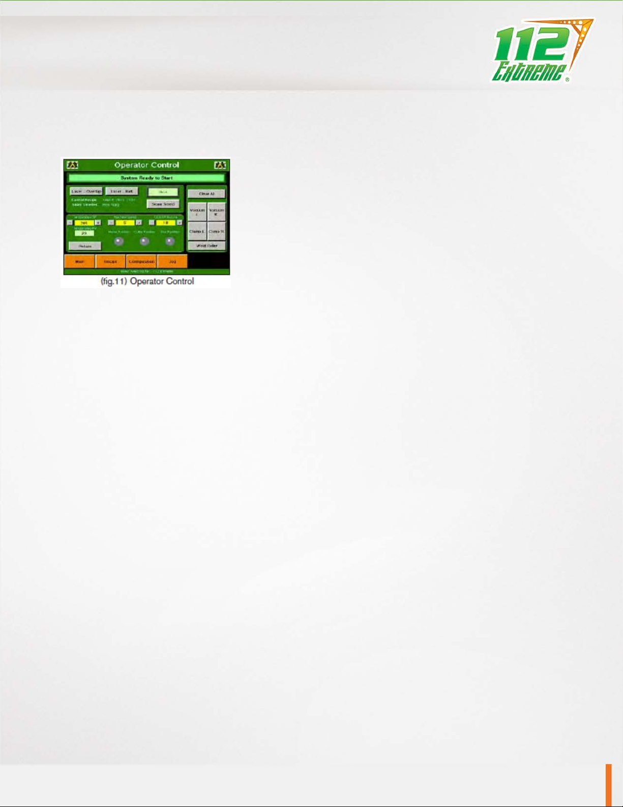
5.0 Definition of Controls
Operator Control
Laser-Overlap: The purpose of this button is when depressed, it will turn
green and turn on the overlap laser and turn off the butt laser.
Laser-Butt: The purpose of this button is when depressed, it will turn green
and turn on the butt laser and turn off the overlap laser.
Weld/Cut: In this box, if weld is showing, the 112 extreme is in the weld
mode. By touching the box it will switch the mode to cut and the 112 will be
in the cut mode.
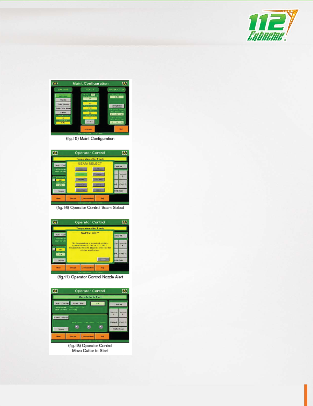
Seam Select: When this box is selected, a bigger box with all seam selections will pop up and the operator
can choose which seam to select.
Temperature SP: The purpose of this box is to show the set point for the temperature and also allow the
operator to manually change the temperature without going into the recipes.
Temperature PV: The purpose of this box is to show the operator what the actual temperature is reading at
the elements.
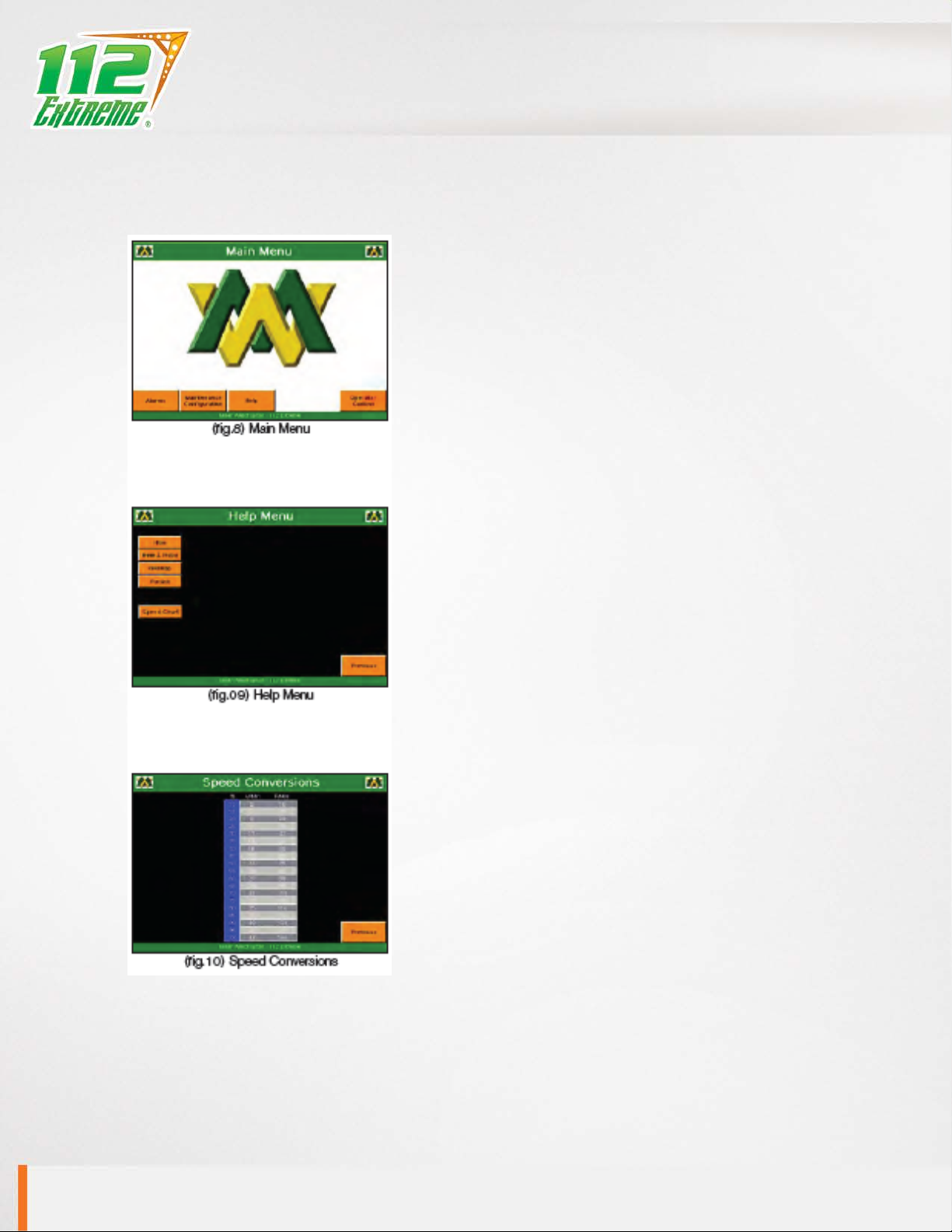
Machine Speed: The purpose of Machine Speed is to control the speed of the carriage assembly during the
welding process. The machine speed number is a percentage of how fast the 112 extreme head carriage
will run. Note: To convert to feet per minute or meter per minute, go to help page under Speed Chart.
Clutch Pressure: The purpose of clutch pressure is to vary the amount of clutch pressure on the weld roller.
This helps eliminate any wrinkling of material. Increasing the clutch pressure will allow the weld roller to
spin faster in relation to the head carriage speed. Decreasing the clutch pressure will spin the weld roller
slower than the head carriage.
Return: The purpose of the Return is to give a means of returning the head carriage to the home position.
This can only be depressed at the end of a weld or cut run.
Clear All: The purpose of this is to give a simpler means to turn off all vacuums and fabric clamps by
touching one spot.
Vacuum Left: The purpose of this function is to turn on or off the left vacuum.
Vacuum Right: The purpose of this function is to turn on or off the right vacuum.
Clamp Left: The purpose of this function is to open or close the left clamp.
Clamp Right: The purpose of this function is to open or close the right clamp.
CHAPTER 5 DEFINITION OF CONTROLS