Soham Impex SI-TIG-300 User manual
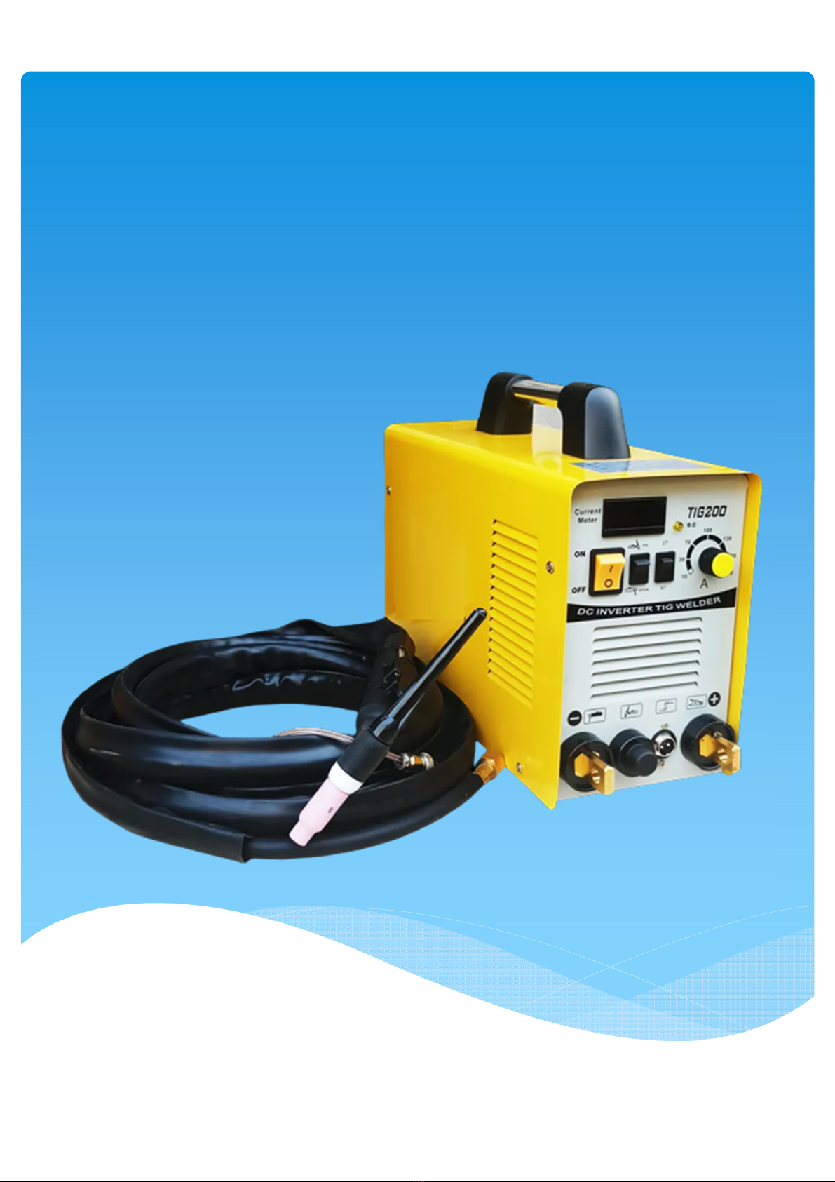
AC/DC GTAW WELDING MACHINE
MANUAL
Vavdi Survey no. 28, Shivam Industrial Area, Street No.3 Plot No.7, Near Sunny Raj Metal,

OPERATING MANUAL
AC/DC GTAW WELDING MACHINE
MODEL : SI -TIG - 300
Works :- Soham Impex,
Vavadi survey no.28, Plot no.7, Near Sunny Raj Metal, Rajkot City,
Gujarat –360004

AC/DC GTAW
WELDING MACHINE
CONTENTS
1. INTRODUCTION OF TIG WELDING MACHINE........................................................................................ 1
2. SAFETY INSTRUCTIONS......................................................................................................................... 3
3. INSTALLATION & COMMISSIONING OF AC/DC TIG WELDING MACHINE.............................................8
4. OPERATING INSTRUCTION..................................................................................................................13
5. COMPONENT DETAILS OFWELDING PLANT ..................................................................................... 15
6. WELDING PARAMETER SELECTION AND SETTING [FRONT PANEL]................................................ 16
7. MAINTENANCE......................................................................................................................................21
8. TROUBLE SHOOTING .......................................................................................................................... 24
9. TIG WELDING TORCH DETAILS........................................................................................................... 28
10. ARGON FLOWMETER REGULATOR DETAILS .....................................................................................30
11. WATER COOLING UNIT DETAILS .........................................................................................................32
12. TECHNICAL SPECIFICATION OF MACHINE......................................................................................... 34
13. BASIC WELDING TECHNIQUE ..............................................................................................................37
[1]
This series of power sources apply IGBT soft switch inverter technology. Its internal control system
applies digital signal processor which ensures quick response to any change during the welding
process so as to achieve precise control of welding process and ensure optimal welding results.
Power source features
This series of power sources are microprocessor controlled and apply MCU + DSP control technology
to improve the control precision. The strong ability of arc self-adjustment ensures a highly stable
welding current against grid fluctuation and arc length change to get optimal results.
Highlights as follows:
- User friendly interface, synergic, easily control;
- Embedded welding expert database, automatic intelligent combination of parameters
- To achieve beautiful ripple pattern of welding seam with the function of Pulse TIG
- Perfect functions of starting arc and reducing melting ball while stopping arc
- Special 4-step mode is suitable for welding metal with good thermal conductivity, with
perfect welding quality when starting arc and stopping arc
- Multiple protection functions
- TIG torch with quick and convenient adjustment of welding current at Torch handle
Functional principle
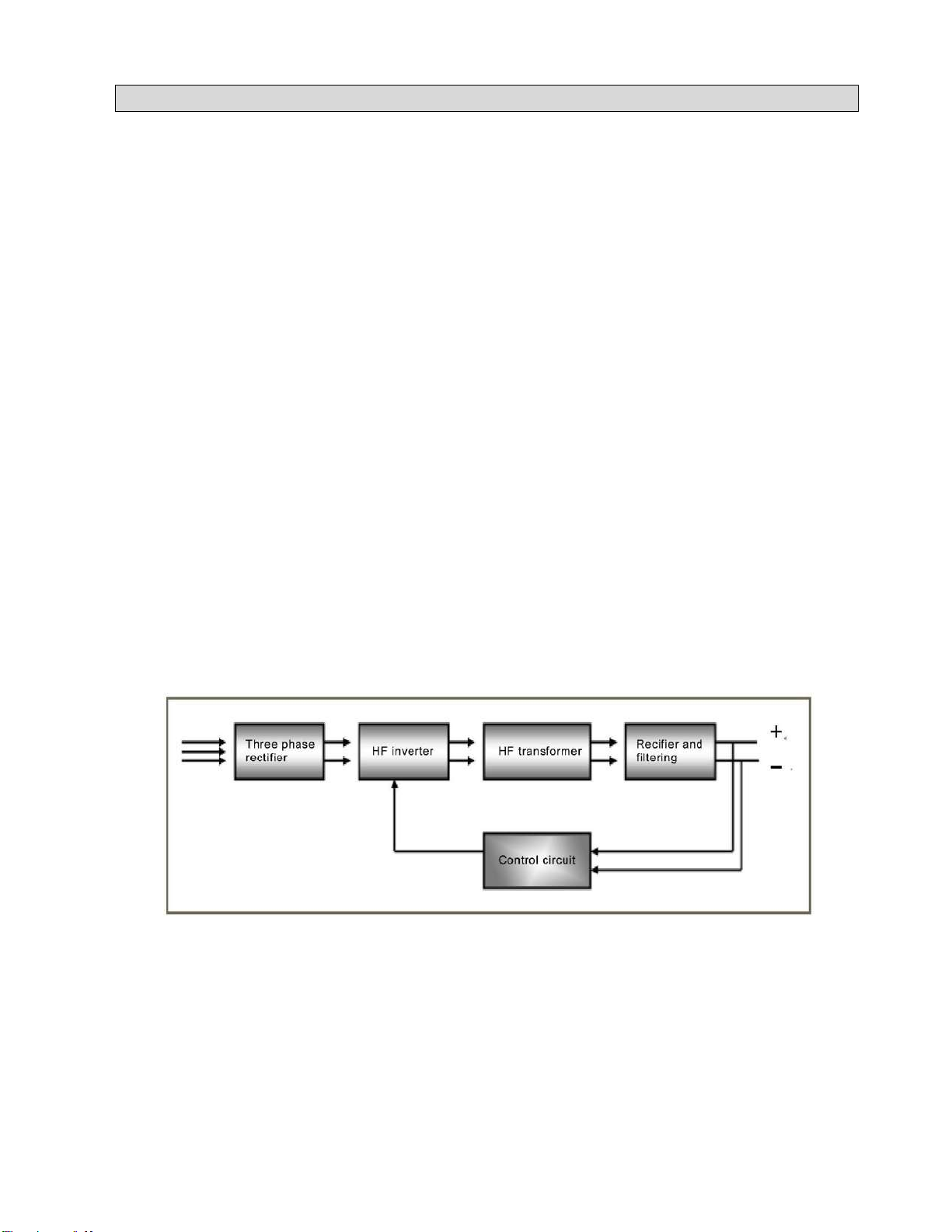
This series of power sources adopt IGBT soft switch inverter technology to improve the dynamic
response rate and make the machines with small size and light weight. The control circuit's closed-loop
control makes the power source enjoy strong ability against power grid fluctuation and perfect welding
performance. The schematic diagram is as shown in Fig. 1-2-1:
Schematic diagram
1. Introduction of GTAW welding machine
[2]
Note!
Exceeding duty cycle can damage the machine and greatly reduce its lifespan
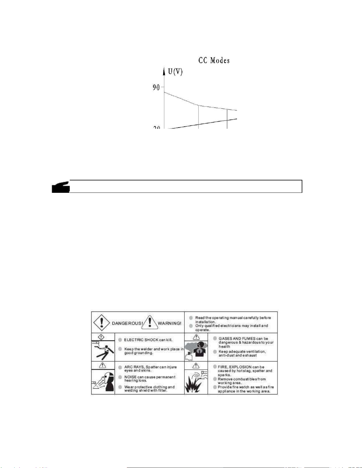
Output characteristics
Output characteristics
Duty cycle
Duty cycle is percentage of 10 minutes that a machine can weld at rated load without overheating. If
overheats, thermostat(s) will open, output stops. Wait for fifteen minutes for the machine to cool down.
Reduce amperage or duty cycle before welding.
Applications
This series of machines have many welding processes and can weld most of the metal materials,
including carbon steel, stainless steel, aluminum and Al-Mg alloy, copper and alloy, etc.
Recommended areas of use as follows:
- Automobile and car manufacture industry
- Chemicalstructure andengineering
- Boiler pressurevesselmanufacture
- Shipbuilding and offshore engineering
- Electric power construction
- Vehicle manufacturing
- Mechanical industry
- Other industries
Warning
Warning

[3]
Danger! “Danger”
indicates an imminently hazardous situation which, if
not avoided, will result in death or serious injury.
Warning! “Warning!”
indicates a possible hazardous situation which, if not
avoided, could result in death or serious injury. The possible
hazards are explained in the text.
Caution! “Caution”
indicates a possible hazardous situation which, if not
avoided, may result in slight or moderate injury.
Note! “Note!”
indicates a situation which implies a risk of impaired
welding result and damage to the equipment.
Important! “Important!”
indicates practical tips and other useful
special-message. It is no signal word for a harmful or dangerous
situation.
Utilization for
intended
purpose only
•
The machine may only be used for jobs as defined by the
―Intended purpose‖.
•
Utilisation for any other purpose, or in any other manner, shall be
deemed to be ―not in accordance with the intended purpose‖. The
manufacturer shall not be liable for any damage resulting from
such improper use.
Safety signs
•
All the safety instructions and danger warnings on the machine
must be kept in legible condition, not removed, not be covered,
pasted or painted cover.
Safety
inspection
•
The owner/operator is obliged to perform safety inspection at
regular intervals.
•
The manufacturer also recommends every 3-6 months for regular
maintenance of power sources.
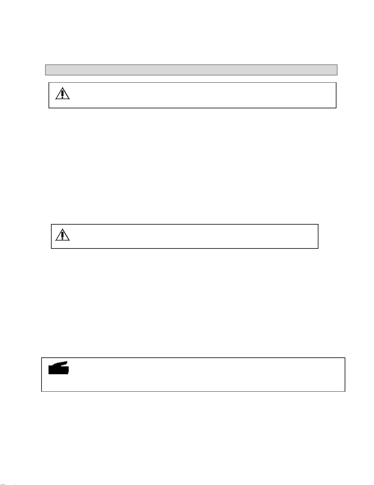
Electric
shock cankill
•
Touching live electrical parts can cause fatal shocks or severe
burns. The electrode and work circuit is electrically live whenever
the output is on. The input power circuit and machine internal
circuits are also live when power is on. In MIG/MAG welding, the
wire, drive rollers, wire feed housing and all metal parts touching
the welding wire are electrically live. Incorrectly installed or
improperly grounded equipment is a hazard.
•
Do not touch live electrical parts of the welding circuit, electrodes
and wires with your bare skin or wet clothing.
2. Safety Instructions

[4]
and body protection while performs the welding.
•
Insulate yourself from work and ground using dry insulating
protection which is large enough to prevent you full area of
physical contact with the work or ground.
•
Connect the primary input cable according to rules. Disconnect
input power or stop machine before installing or maintenance.
•
If welding must be performed under electrically hazardous
conditions as follow: indamp locations or wearing wet clothing; on
metal structures such as floors, gratings, or scaffolds; when in
cramped positions such as sitting, kneeling, or lying; or in
occasion when there is a high risk of unavoidable or accidental
contact with the work piece or ground. Must use additional safety
precautions: semiautomatic DC constant voltage (wire) welder,
DCmanual (Stick) welder and AC welder with reduced open-load
voltage.
•
Maintain the electrode holder, ground clamp, welding cable and
welding machine in good, safe operating condition. Replace
damaged part immediately.
Electric and
magnetic
fields (EMF)
may be
dangerous
•
If electromagnetic interference is found to be occurring, the
operator is obliged to examine any possible electromagnetic
problems that may occur on equipment as follow:
-
minas, signal and data-transmission leads
-
IT and telecoms equipment
-
measurement and calibration devices
-
Wearers of pacemakers
•
Measures for minimizing or preventing EMC problems:
-
Mains supply
If electromagnetic interference still occurs, despite the fact that
the mains connection in accordance with the regulations,
take additional measures
-
Welding cables
Keep these as short as possible
Connect the work cable to the work piece as close as possible to the
area being welded.
Lay tem well away from other cables.
Do not place your body between your electrode and work cables.
-
Equipotential bonding
-
Work piece grounding (earthing)
-
Shielding
Shield the entire welding equipment and other equipment nearby.
ARC rays can
burn.
•
Visible and invisible rays can burn eyes and skin.
•
Wear an approved welding helmet or suitable clothing made from
durable flame-resistant material (leather, heavy cotton, or wool) to

[5]
protect your eyes and skin from arc rays and sparks when welding
or watching.
•
Use protective screens or barriers to protect other nearby
personnel with suitable, non-flammable screening and/or warn
them not to watch the arc nor expose themselves to the arc rays
or to hot spatter or material.
Fumes and
gases can be
dangerous
•
Welding may produce fumes and gases, breathing these fumes
and gases can be hazardous to your health.
•
When welding, keep your head out of the fume. If inside, ventilate
the area at the arc to keep fumes and gases away from the
breathing zone. If ventilation is not good, wear an approved
air-supplied respirator.
•
Work in a confined space only if it is well ventilated, or while
wearing an air-supplied respirator.
•
Welding fumes and gases can displace air and lower the oxygen
level causing injury or death. Always use enough ventilation,
especially in confined areas, to insure breathing air is safe.
Welding and
cutting
sparks can
cause fire or
explosion
.
•
When not welding, make sure the electrode circuit is not touching
the work or ground. Accidental contact can cause sparks,
explosion, overheating, or fire. Make sure the area is safe before
doing any welding.
•
Welding and cutting on closed containers, such as tanks, drums,
or containers, can cause them to blow up. Make sure proper steps
have been taken.
•
When pressure gas is used at the work site, special precautions
are required to prevent hazardous situations.
•
Connect work cable to the work as close to the welding zone as
practical to prevent welding current from passing too long and
creating fire hazards or overheat.
•
Wear oil-free protective garments such as leather gloves, heavy
shirt, cuffless trousers, high shoes, and a cap. Wear ear plugs
when welding out of position or in confined places. Always wear
safety glasses with side shields when in a welding area.
•
Be attention that welding sparks and hot materials from welding
can easily go through small cracks and openings to adjacent
areas and start a fire. Remove fire hazardous from the welding
area, if not possible, cover them thoroughly. Do not weld where
flying sparks can strike flammable material and where the
atmosphere may contain flammable dust, gas, or liquid vapors
(such as gasoline).
•
Protect yourself and others from flying sparks and hot metal.
Remove any combustibles from operator before perform any
welding.

[6]
•
Keep a fire extinguisher readily available.
•
Empty containers, tanks, drums, or pipes which have
combustibles before perform welding.
•
Apply correct fuses or circuit breakers. Do not Remove stick
electrode from electrode holder or cut off welding wire at contact
tip when not in use.
•
Oversize or bypass them.
Cylinder can
explode if
damaged.
•
Pressure gas cylinders contain gas under high pressure. If
damaged, a cylinder can explode. Since gas cylinders are
normally part of the welding process, be sure to treat them
carefully.
•
Cylinders should be located away from areas where they may be
struck or subjected to physical damage. Use proper equipment,
procedures, and sufficient number of persons to lift and move
cylinders.
•
Always install cylinders in an upright position by securing to a
stationary support or cylinder rack to prevent falling over or
tipping.
•
Keep a safe distance from arc welding or cutting operations and
any other source of heat, sparks, or flame.
•
No touching cylinder by welding electrode, electrode holder or
any other electrically ―hot‖ parts. Do not drape welding cables or
welding torches over a gas cylinder.
•
Use only correct compressed gas cylinders, regulators, hoses,
and fittings designed for the process used; maintain them and
associated parts in good condition.
•
Use only compressed gas cylinders containing the correct
shielding gas for the and properly operating regulators designed
for the gas and pressure used. All hoses, fittings, etc. should be
suitable for the application and maintained in good condition.
•
Open the cylinder valve slowly and keep your head and face
away from the cylinder valve outlet.
•
Valve protection caps should be kept in place over valve expect
when the cylinder is in use or connected foruse.
Hot parts can
burn
•
Do not touch hot parts with bare hand or skin.
•
Ensure equipment is cooled down before perform anywork.
•
If touching hot parts is needed, use proper tools and/or wear
heavy, insulated welding gloves and clothing to prevent burns.
Flying metal
or dirt can
injure eyes
•
When welding, chipping, wire brushing, and grinding can cause
sparks and flying metal. It can hurt your eyes.
•
Remember wear appropriate safety glasses with sideshields
when in welding zone, even under your welding helmet.

[7]
Noise can
damage
hearing
Moving parts
can injure
•
Noise from someprocesses or equipment can damage hearing.
•
Remember wear approved ear protection to protect ears if noise
level is high.
•
Stay away from moving parts such as fans.
•
Stay away from pinch points such as drive rolls.
•
Keep all doors, panels, covers, and guards closed and securely in
place.
•
Have only qualified persons remove doors, panels, covers, or
guards for servicing and maintenance.
•
Reinstall doors, panels, covers, or guards when servicing and
maintenance is finished and before reconnecting input power.
Overuse can
cause
overheating
Safety
markings
•
Use machine follow duty cycle. Reduce current or reduce duty
cycle before starting to weld again.
•
Allow cooling period.
•
Do not block or filter airflow to unit.
Equipment with CE-markings fulfils the basic requirements of the
Low-Voltage and Electromagnetic Compatibility Guideline (e.g.
relevant product standards according to EN 60 974).
[8]
Warning!
Operating the equipment incorrectly can cause serious injury and damage. Do not
use the functions described here until you have read and completely understood ―safety
rules‖.
Warning!
Amachine that topples over or falls from its stand can cause injury. Place
equipment on an even, firm floor in such a way that it stands firmly.
Note!
Inadequately dimensioned electrical installations can lead to serious damage. The mains
lead, and its fuse protection, must be dimensioned in accordance with the local power supply.
The technical data shown on the nameplate shall apply.
Utilization for intended purpose only
The power source may only be used for DC TIG , AC TIG , MMA , PULSE DC TIG , PULSE AC TIG
welding . Utilization for other purposes, or in any other manner, shall be deemed to be "not in
accordance with the intended purpose". The manufacturer shall not be liable for anydamage resulting
from such improper use. Operate, inspect and maintain should follow all the instructions given in this
manual.
Machine installation rules
Protection degree of this power source is IP23. However, the internal key components must be
protected from direct soaking.
The venting duct is very important for safety protections. When choosing the machine location, make
sure it is possible for the cooling air to freely enter and exit through the louvers on the front and back of
machine. Any electro conductive metallic dust like drillings must not be allowed to get sucked into the
machine.
Power source connection
- The power source is designed to run on the voltage given on thenameplate.
- The mains cables and plugs must be mounted in accordance with the relevant technical standards.
- The power supply sockets that come with power source are designed to use strictly according to the
marked voltages.
3. INSTALLATION AND COMMISSIONING OF AC/DC GTAW WELDINGMACHINE
[9]
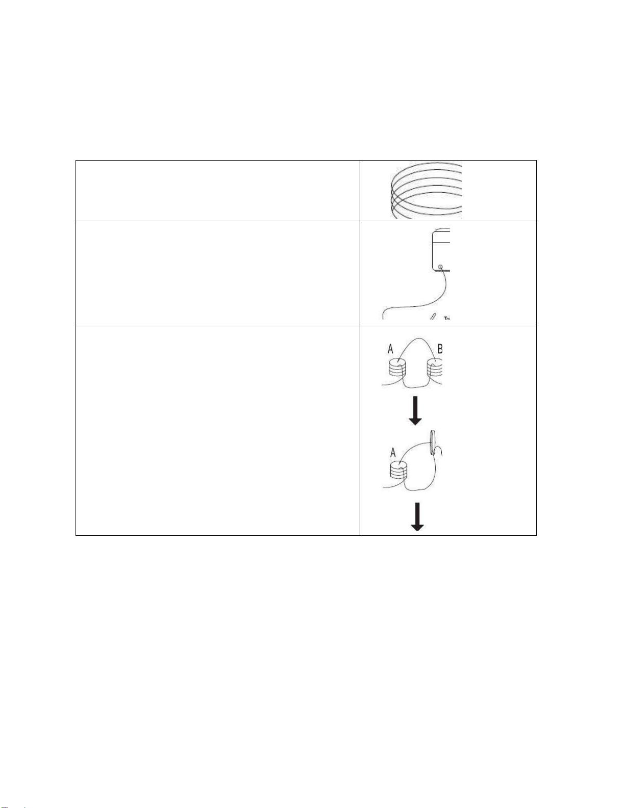
Welding cables instruction
When welding, please pay attention to the followings:
a. The welding cables should be kept as short as possible;
b. If extended cable is used, please do as shown in Fig. 3-4-1.
Wrong
Coil the excess ground cable and welding cable in same
direction respectively.
Correct
Straighten the ground cable and welding cable and make
them close to each other.
Bundle the ground cable and welding cable together,
running the wires close to the ground.
Correct
When the excess cables are only be used by rolling up,
coil the cables to two windings in reverse direction and
overlap them.
The number of turns for A is same as the number for B.
Handle the welding cable and ground cable according to
above-mentioned method.
Welding cables instruction
Connecting to a mains electrical supply
THIS MACHINE IS OF AN INDUSTRIAL SPECIFICATION AND MUST BE FITTED TO A MINIMUM of
16AMP 415V MAINS INPUT
Connecting to an Engine Driven Generator
If connecting this machine to an engine driven generator please ensure the following
Minimum Generator KVA Output –20 KVAcontinuous
Generator to be fitted with AVR (automatic voltage regulation)
DO NOT USE ON A GENERATOR WITHOUTAVR
Connecting to a generator without the above minimum requirements will in-validate your
warranty.

[10]
Commissioning of AC/DC GTAW machine
Back panel machine connections
POWER SOURCE
1.
On/Off Switch
2.
Mains input cable :
Fit required plug as per your electrical installation
3.
Gas Inlet : Input connector
Connect input gas hose ensuring connection is tight . Gas hose
from Flow meter is connected here.
4.
Main chassis earth bolt :
If you experience interference you can fit extra earth to this point
(Not normally used)

[11]
Front panel machine connections
A:- Connections for TIG (GTAW) Welding
1.
Negative power connector -
Connect Tig Torch connector to power connector by inserting and
twisting until tight
ENSURE TIG TORCHIS FITTED TO NEGATIVE CONNECTOR OTHERWISE YOU WILL
EXPERIENCE TUNGSTEN BURNBACK
2.
Positive power connector +
Connect the earth lead to by inserting and twisting until tight and
the earth clamp to work/bench
3.
Gas outlet - Quick release type
Connect the torch gas hose
4.
Torch control socket 7-Pin
Connect torch control plug
5.
FRONT PANEL :
All welding Process and Parameter are SET and Operate operated from
this panel . Its Display will show all values. Details of each buttons and is use is elaborated
in chapter 6
6.
Water Inlet:
Connect water hose from TIG torch : Water input to cool the TIG torch
7.
Water outlet:
Connect water hose from TIG torch : Water Output from the TIG torch
8.
Water Circulating Tank:
Tank with Water Inlet and Wateroutlet
9.
Input Supply cable for water tank:
To make Water Cooling unitON

[12]
B:- Connections for STICK MMA (SMAW) Welding
1.
Negative power connector -
Connect the earth lead to by inserting and twisting until tight and the
earth clamp to work/bench
2.
Positive power connector +
Connect the electrode holder by inserting and twisting until tight
All other front panel connectors are not used for MMA welding
●
Gas cylinder installation
Gas cylinder installation
1. Stand the gas cylinder on the trolley and secure it by fixing the cylinder
strap around a point in the top third of the cylinder-but never around the
neck of the cylinder.
2. Take the protective cap off the gas cylinder.
3. Gently turn the gas-cylinder value anticlockwise, and blow off any dust
and dirt.
4. Screw the pressure regulator onto the gas cylinder and tighten it.
5. Connect the shielding-gas connector to the pressureregulator.
Note :-
To avoid a High Frequency shock keep the Tig torch in good condition and replace if any of
the insulation is damaged.
Connect the gas input hose to gas regulator and use ‗Gas Test ‗ Button to Set gas flow /
pressure to 8-12 LPM. Make sure gas bottle is secured and properly mounted in trolley to
avoid injury.

[13]
Welding in TIG mode –No Pulse –No remote footpedal
1. Connect the Tig Torch to machine, connect earth lead to machine & work piece.
2. Set to Tig mode pulse off
3. Select 2 or 4 way torch operation
4. Connect Argon gas and set flow to approx 8-12LPM
5. Adjust welding amps to desired welding current
6. Press the Tig torch switch to start welding and release to finish
Welding in TIG mode –with Pulse –No remote footpedal
1. Connect the Tig Torch to machine, connect earth lead to machine & work piece.
2. Set to Tig mode pulse on
3. Select 2 or 4 way torch operation
4. Connect Argon gas and set flow to approx 8-12LPM
5. Adjust Pulse freq. to desired setting (how often pulse happens)
6. Adjust base amperage %
7. Adjust pulse width to desired setting (how long pulse happens)
8. Adjust main current for maximum welding current
9. Press the Tig torch switch to start welding
The benefits of pulse welding is the ability to control the weld pool and amount of heat absorbed by
work resulting in a smaller heat affected zone which results in fewer deformations and reduced chance
of cracking. There are no set rules for pulse welding as this is down to personal choice by the welder.
Welding in TIG mode –with Remote amperage torch
1. Connect the Tig Torch to machine, connect earth lead to machine & work piece.
2. Set to Tig mode pulse OFF or Tig mode pulse ON In welding with pulse in remote torch, the foot
pedal controls peak main welding amperage.
3. Select 2T or 4T torch operation –Ensure the PEDAL (remote) LED is illuminated.
4. Connect Argon gas and set flow to approx 8-10LPM
5. Adjust welding amps knob on machine to desired maximum welding current that remote torch will go
to.
7. Press the torch switch to start welding. (on maximum it will go to maximum amps set on machine)
Welding in TIG mode –with Remote foot pedal
1. Connect the Tig Torch to machine, connect earth lead to machine & work piece.
2. Connect remote foot pedal to machine
3. Set to Tig mode pulse off or Tig mode pulse on In welding with pulse in foot pedal, the foot pedal
controls peak main welding amperage
4. Select 2 way torch operation - Foot pedal will not work in 4-WAY mode
5. Connect Argon gas and set flow to approx 8-12LPM
6. Adjust peak current knob on machine to desired maximum welding current that foot pedal will go to.
7. Press the foot pedal to start welding.
4. OPERATING INSTRUCTION

[14]
Note: When welding with remote foot pedal
Upon pressing of foot pedal welding arc will start, if you
find it hard to start arc push pedal down a bit further to aid starting. Press pedal fully to start weld, upon
weld pool formation you can release the pedal to decrease amperage to sustain perfect weld pool and
increase again as required to sustain weld characteristics. The foot pedal adjusts from Start (min)
current to maximum current as set on main current knob on front of machine.
Advantage of Remote current control on Torch switch : No need to vary current while starting as well
as operating TIG welding only if welder need variation then only you need to adjust. Foot switch is
needed always to press and foot pressing can not keep current at always the same level may vary as
foot shakes during welding.
Tig tungsten size / amperage guide
All values below are based on using pure argon shielding gas. Other current values may be employed
depending on the shielding gas and application
ELECTRODE RATINGS
Electrode
Diameter (mm)
2% Thoriated on DC (amps)
Red Tip –Grind to point
Pure
Tungsten on
DC (amps)
Zirconiated 0.8% Tungsten
on AC (amps) White Tip –
No need to grind
1.0mm / 0.040‖
5 - 80
30
20 - 60
1.6mm / 1/16‖
40- 150
80
40 - 100
2.4 mm/ 3/32‖
140 - 250
130
80 - 180
3.2mm / 1/8‖
240 - 400
180
160 - 250
4.0mm / 5/32‖
380- 500
240
220 - 320
4.8mm / 3/16‖
500- 750
300
280 - 390
6.4mm / 1/4‖
750 - 1000
400
360 - 525
Welding in STICK MMA(SMAW) Mode
1. Fit MMA electrode holder to + terminal on machine
2. Fit earth lead to - terminal on machine and to workpiece
3. Select stick on front panel
4. Place electrode in holder
5. Select desired welding current with selector knob
6. Select desired MMA options, Arc Force, Hot start time and Amps
7. Strike arc and weld
WARNING!
ELECTRIC SHOCK CAN KILL
When machine is switched to MMA mode, output terminals are always live, take care and do not touch
electrode and earth by person at same time, otherwise electric shock will occur.
The foot pedal has no affect on welding current in MMA mode and the gas flow and high frequency
starting circuit is disabled.
NOTE:-
Please refer to
Chapter 6 Front Panel
for selecting and setting all parameters For TIG/MMA
welding.

[15]
Welding Plant components
AC/DC GTAW Welding Plant Includes
-
Power source with Inbuilt Water cooling unit
-
TIG Welding torch
-
Argon gas regulator with flow meter and gas hose
-
Welding cable with Electrode Holder
-
Ground Earthling cable with Clamp
-
Standard tool kit for operating plant
Scope of supply by Consignee:
-
Input Supply 3 PHASE , 340 to 460 VAC , 50 Hz
-
Argon gas cylinder (Provided by consignee)
-
Welding material (Electrode /wire)
5. COMPONENT DETAILS OF WELDING PLANT

[16]
1.
Memory store function :
There are memory store programs to enable you to select required parameters for job in hand and then
store to select channel. Press memory button until required program you wish to store is showing in
LED Then enter parameters as required, now press and hold save button for 3 seconds and release,
the green save LED will now light for about 2 seconds and then go out. The parameters have now
been stored. The red select LED will then come back on, if you make any more adjustments these will
not be save until you save again
2.
Save button: to save the parameters on controlpanel
3.
Select :
Parameter selector Button :
Press this button to scroll from left (A) to right (L) to select the
machine parameters an adjust the value of the same within 2 seconds or you have to repeat the
procedure again as LED will move to its initial (D)position.
4.
Parameter Sequence : From A to L as explained below :
A.
Pre-flow gas :
Adjustable from 0 - 25 seconds, this enables the backed up gas pressure to be
released from torch before actual arc is started. Common settings for most application is about .3 to.5
seconds - If welding stainless steel etc sometimes a longer pre-flow is required.
6. WELDING PARAMETER SELECTION AND SETTING [ FRONT PANEL]

[17]
B.
Start Amperage :
This allows you to set the initial start current from 5A DC and 10A AC. In 4T
mode when trigger is pressed and held you will remain at start amps, when you let go machine will then
go to main set amps. Do not set the start amperage too low for tungsten size otherwise you may
experience sluggish / non arc starting. I.E A 3.2mm tungsten is for high range 160+ amps welding, so
you would not need to set start amps at 5. The thicker the tungsten used the higher the start amperage
has to be. We recommend to achieve faster arc starting:-1.0mm Tungsten - 5 Amps minimum1.6mm
Tungsten - 15-20 Amps minimum2.4mm Tungsten - 40 Amps minimum3.2mm Tungsten - 60 Amps
minimum Note:
C.
Up-Slope :
Adjustable from 0 - 25 seconds, This allows you to gradually increase the amperage
from start amps to main amps when using torch trigger operation.
D.
Welding Amps : Main current control :
This adjusts the main welding current and is shown in
L.E.D when welding is in process. Welding range AC is 5A to 300AWelding range DC is 3A to 300A
E.
Pulse Time ON (%) : Pulse width
When pulse welding you have the main (peak) amperage and
base (background)amperage set. By adjusting the width you determine which will be more prominent,
the pulse or the base. This is adjustable from 5-95%. At a low % the base current will be on long so you
will reduce heat input. At a high % the pulse current will be more prominent so you will get increased
heat input..
F.
Pulse Amps (%) :
This sets the base amperage as a % of main amps set. I.E if mains amperage is
120A and you set to 50%, base amps will be 60A.
G.
Pulse Frequency (Hz) Adjustment :
This can be adjusted as follows: DC Mode 0.1 to 500HzAC
Advanced Squarewave 0.1 - 250HzAC Soft Square, Triangular and Sinewave 0.1 - 10HzAdvanced AC
Pulse 0.1 - 10Hz
H.
AC Balance
This sets the % of electrode positive used during AC welding to provide a cleaning
action as alloys have a oxide layer that has a higher melting temperature than the base metal and this
needs to be lifted off. Soyou can control the amount of cleaning or penetration. Too much cleaning will
cause the tungsten to wobble and split, Too little cleaning can result in a dirty dull weld. So as you
increase the % the more cleaning will happen however less penetration will be achieved. For most
situations a setting of 30 - 40% will give you a good clean weld finish, If you go above 50% you will find
the tungsten will overheat and the end can fall of into weld pool. If you find you are getting tungsten
wobble using 30-40% balance then you may need to go up a tungsten size.
I.
AC Frequency
Transformer based welders are normally fixed at 60Hz, due to the advanced inverter
technology you can adjust from 20 - 250Hz.The higher the AC frequency the narrower the arc
becomes allowing you to have a more precise weld bead and penetration. This can also quicken up
travel speed and ideal for production welding. You will hear the pitch of the weld noise get higher, this
is normal. Welding at lower frequency will give reduced control of arc and a wider weld pool.
J.
Down-Slope
Adjustable from 0 - 25 seconds, This allows you to gradually decrease the amperage
from main amps to end/final amps when using torch trigger operation.
Table of contents
Other Soham Impex Welding System manuals

Popular Welding System manuals by other brands


Murex
Murex Tradesmig 280?3 instruction manual

Northern Industrial
Northern Industrial Flux Core 125 Quick setup guide

Cloos
Cloos qineo PULSE MASTER-Plus operating instructions

Oerlikon
Oerlikon CITOLINE 3000T Safety instruction for use and maintenance

STAMOS
STAMOS S-MMA-250PI user manual

GYS
GYS GYSPOT ARCPULL 350 manual

Everlast
Everlast CT416 owner's manual

Lincoln Electric
Lincoln Electric POWER MIG SVM167-A Service manual

Klutch
Klutch MIG 140i owner's manual

Miller Electric
Miller Electric Spectrum 875 Auto-Line owner's manual

Rothenberger
Rothenberger ROWELD P 250 A Instructions for use

Tregaskiss
Tregaskiss TOUGH GUN Technical guide