Sola HD 500 User manual

Uninterruptible Power Systems
SDU Series
500, 850, 500-5, 850-5
Instruction Manual

SDU Series Instruction Manual • ii
While every precaution has been taken to ensure accuracy and completeness in this
manual, SolaHD assumes no responsibility, and disclaims all liability for damages resulting
from use of this information or for any errors or omissions.
©2008 SolaHD. All rights reserved throughout the world. Specications are subject to
change without notice.
®SolaHD name and logo are registered trademarks of EGS Electrical Group, LLC. All
names referred to are trademarks or registered trademarks of their respective owners.
Aunque se han tomado todas las precauciones para asegurar la exactitud y acuciosidad de
este manual, SolaHD no asume responsabilidad alguna, y rechaza toda responsabilidad
por daños que pudieran resultar debido al uso de esta información o por cualquier error u
omisión.
©2008 SolaHD. Todos los derechos reservados en el mundo entero. Las especicaciones
pueden cambiar sin previo aviso.
El nombre y el logotipo de ®SolaHD son marcas registradas de EGS Electrical Group, LLC.
Todos los nombre mencionados son marcas comerciales o registradas de sus respectivos
titulares.
Bien que toutes les précautions aient été prises an d’assurer que les renseignements du
présent manuel sont complets et exacts, Sola/Hevi-Duty n’assume aucune responsabilité,
et décline toute responsabilité pour des dommages découlant de l’utilisation de cette
information ou de toute erreur ou omission.
©2008 SolaHD Tous droits réservés mondialement. Les caractéristiques techniques sont
sujettes à modication sans préavis.
Le nom et le logo ®SolaHD sont des marques déposées de EGS Electrical Group, LLC.
Tous les noms évoqués sont des marques de commerce ou des marques déposées de
leurs propriétaires respectifs.

Table of Contents/Índice/Table des matières
SDU Series Instruction Manual • iii
English
1.0 Important Safety Instructions .......................................................................................................... 4–5
2.0 Warnings Dened ............................................................................................................................... 5
3.0 Introduction ......................................................................................................................................... 6
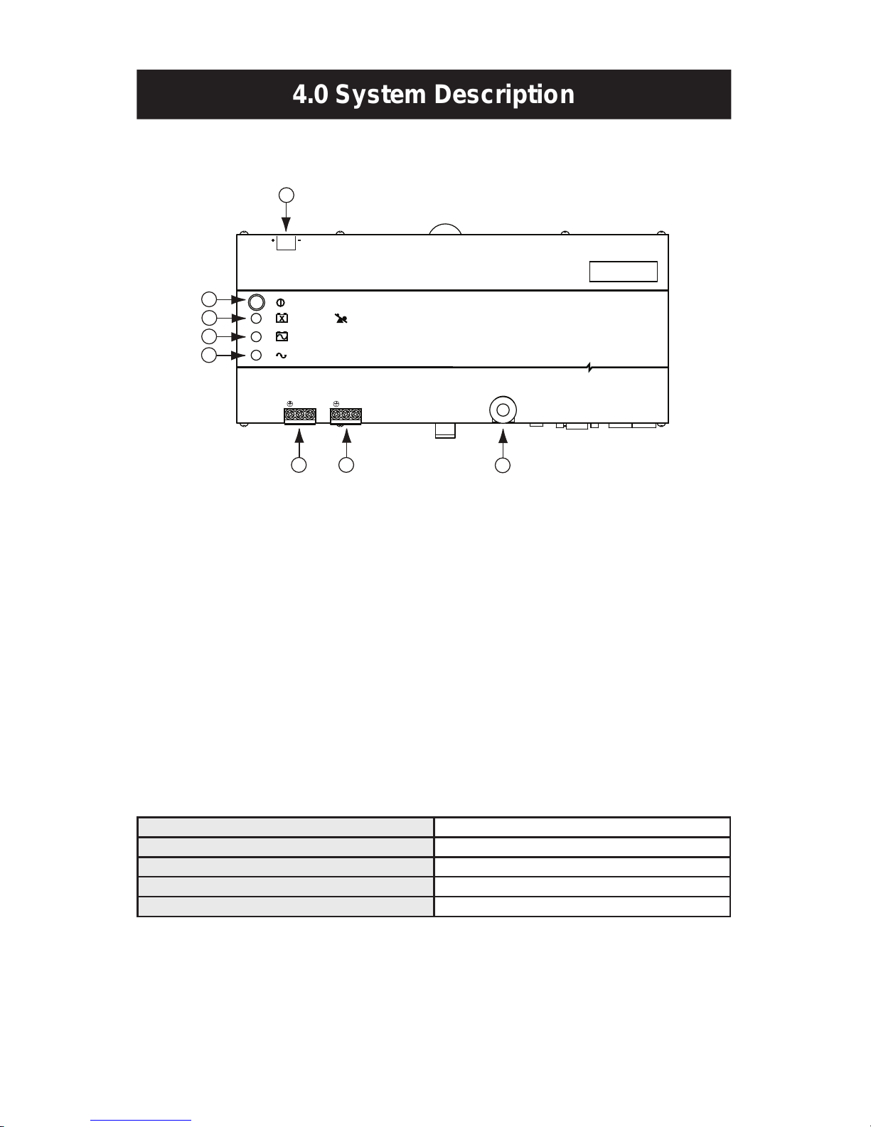
4.0 System Description ......................................................................................................................... 7–8
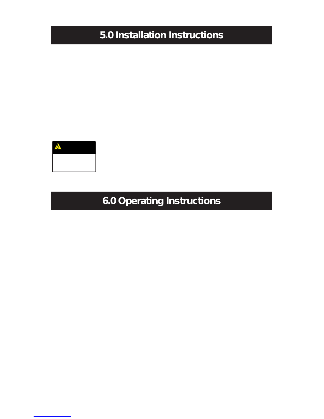
5.0 Installation Instructions ....................................................................................................................... 9
6.0 Operating Instructions .................................................................................................................. 9–10
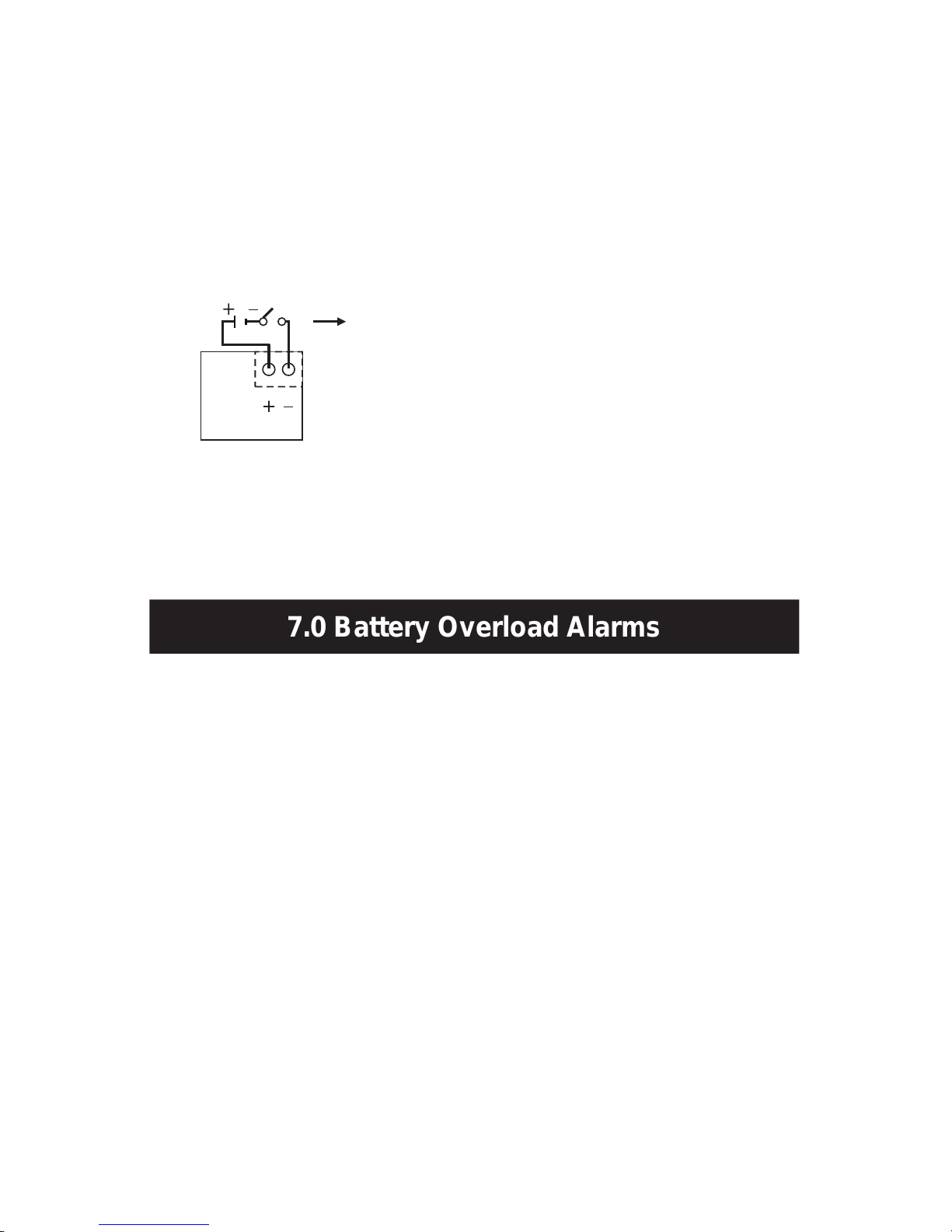
7.0 Battery Overload Alarms ................................................................................................................... 10
8.0 PIN-Out Conguration for DB9 Connector ....................................................................................... 11
9.0 Battery Backup Times ....................................................................................................................... 11
10.0 Troubleshooting .............................................................................................................................. 12
11.0 Storage ........................................................................................................................................... 12
12.0 Specications ................................................................................................................................. 13
13.0 Conditions for Safe Use of SDU 500 & 850 .............................................................................. 14–15
14.0 Product Registration & Warranty Information ................................................................................. 15
Español
1.0 Instrucciones importantes de seguridad ..................................................................................... 16–17
2.0 Denición de advertencias ............................................................................................................... 17
3.0 Introducción ...................................................................................................................................... 18
4.0 Descripción de sistema ...............................................................................................................19–20
5.0 Instrucciones de instalación ............................................................................................................. 21
6.0 Instrucciones de operación ......................................................................................................... 21–22
7.0 Tiempo de autonomía de la batería (Alarma) ................................................................................... 23
8.0 Conguración de disposición de las clavijas del conector DB9 ........................................................ 23
9.0 Tiempo de reserva de la batería ....................................................................................................... 24
10.0 Almacenamiento ............................................................................................................................. 24
11.0 Solución de problemas ................................................................................................................... 25
12.0 Especicaciones ............................................................................................................................. 26
13.0 Registro del Producto y Información sobre la Garantía .................................................................. 27
Français
1.0 Instructions importantes sur la sécurité ...................................................................................... 28–29
2.0 Dénition des avertissements ........................................................................................................... 29
3.0 Introduction ....................................................................................................................................... 30
4.0 Description du système .............................................................................................................. 31–32
5.0 Instructions d’installation .................................................................................................................. 33
6.0 Instructions d’utilisation .............................................................................................................. 33–34
7.0 Alarmes de la batterie de secours .................................................................................................... 35
8.0 Conguration des broches de sortie du connecteur DB9 ................................................................. 35
9.0 Temps de secours de batterie .......................................................................................................... 36
10.0 Entreposage ................................................................................................................................... 36
11.0 Dépannage ..................................................................................................................................... 37
12.0 Spécications ................................................................................................................................. 38
13.0 Enregistrement du produit et information sur la garantie ................................................................ 39

SDU Series Instruction Manual • 4English version
1.0 Important Safety Instructions
This manual contains important safety instructions that should be followed during
the installation of the Uninterruptible Power System (UPS). Please read all safety,
installation, and operating instructions before attempting to install or operate the
UPS. Please adhere to all warnings on the unit and in this manual during installa-
tion and operation.
The UPS is designed for Industrial or Commercial use and can be installed and
operated by individuals without previous training.
1.1 Safety Precautions—Warnings
• To prevent the risk of re or electric shock, install the UPS in a temperature
and humidity controlled ventilated enclosure, free of conductive contaminants,
moisture, flammable liquids, gases, and corrosive substances.
• Operate the UPS only from a properly grounded (earthed) ac supply.
• To reduce the risk of electric shock, do not remove the cover, as it has no user-
serviceable parts inside. Some components are live, even when ac power is
disconnected. For service, contact a qualied technician.
Although your UPS has been designed and manufactured to assure personal
safety, improper use can result in electrical shock or re. To ensure safety, please
observe the following rules:
• Turn OFF UPS and disconnect the ac supply before cleaning. Do not use
liquid or aerosol cleaners. A dry cloth is recommended to remove dust from the
surface of your UPS.
• Do not install or operate the UPS in or near water.
• Do not place the UPS on an unstable cart, stand, or table.
• Do not place the UPS under direct sunlight or close to heat-emitting sources.
• To allow proper ventilation of the UPS, do not block or cover the top and bottom
sides of the unit.
• Never block or insert any objects into the ventilation holes or other openings of
the UPS. Keep all vents free of dust accumulation that could restrict airflow.

SDU Series Instruction Manual • 5English version
• Follow all warnings and instructions marked on the UPS. Do not attempt to
service the UPS, as it has no user-serviceable parts inside. Refer all repairs to
qualied service personnel.
• Do not dispose of batteries in a re; they may explode.
• Do not open or damage the battery. Released electrolyte is harmful to the skin
and eyes and may be toxic.
If your UPS demonstrates any of the following conditions, turn OFF the UPS,
disconnect the ac supply and contact your local distributor, SolaHD representa-
tive or SolaHD Technical Support at 1-800-377-4384.
• Liquid has been spilled on the UPS.
• The circuit breaker opens frequently.
• The UPS does not operate in accordance with the user manual.
1.2 Conditions of Use
Your UPS provides conditioned power to connected equipment. The maximum
load must not exceed that shown on UPS rating label. If uncertain, contact your
distributor or SolaHD Technical Support at 1-800-377-4384.
U.S. Only: For Conditions of Acceptability in accordance with UL 508A, see “13.0
Conditions for Safe Use of SDU 500 & 850”.
2.0 Warnings Dened
Danger: Indicates an imminently hazardous situation
that, if not avoided, will result in death or serious injury.
This signal word is limited to the most extreme situations.
Warning: Indicates a potentially hazardous situation that,
if not avoided, could result in death or serious injury.
Caution: Indicates a potentially hazardous situation that,
if not avoided, may result in minor or moderate injury. It
may also be used to alert against unsafe practices.

SDU Series Instruction Manual • 6English version
3.0 Introduction
Congratulations on your choice of the SDU Uninterruptible Power System (UPS).
The SDU is a compact, “Off-Line” DIN rail mountable UPS, which provides condi-
tioned power to sensitive electronic equipment. It supplies connected equipment
with stepped approximation to sinewave power to simulate the power generated
by the utility.
The SDU is a powerful, microprocessor-controlled UPS. Input voltage range is
80% to 110% (ideal protection for the critical connected loads). Battery charging
occurs automatically when ac power is applied, no need to switch ON the UPS.
When power fails, the UPS can be automatically turned OFF, as long as the
connected loads are not operating to save the battery energy. The SDU also
includes an automatic self-test feature to test the UPS function and battery. If the
battery is no longer useful, the unit will sound an alarm and an LED indicator will
illuminate.
NOTE: This equipment has been tested and found to comply with the limits for
a Class A digital device, pursuant to Part 15 of the FCC Rules. These limits are
designed to provide reasonable protection against harmful interference in an
industrial installation. This equipment uses, generates and can radiate radio
frequency energy and, if not installed and used in accordance with the instruc-
tions, may cause harmful interference with radio communications. However, there
is no guarantee that interference will not occur in a particular installation. If this
equipment does cause harmful interference to radio or television reception, which
can be determined by turning the equipment OFF and ON, the user is encour-
aged to try to correct the interference by one or more of the following measures:
• Reorient or relocate the receiving antenna.
• Increase the separation between the UPS and the receiver.
• Connect the UPS into a circuit different from that which the receiver is
connected.
• Consult the dealer or an experienced radio/TV technician for help.

SDU Series Instruction Manual • 7English version
4.0 System Description
4.1 Front Panel
Surge Protection
Remote
Vout
N
Input:
Industrial UPS
S O L A
POWER ON / OFF / TEST
REPLACE BATTERY /
ON BATTERY (BACK UP MODE)
AC INPUT NORMAL (AC MODE)
OVERLOAD
Circuit Breaker
L N L
Output:
REMOTE
ON / OFF
+5V–30 V dc
+–
1
2
3
4
5 6 7
8
1. Power ON/OFF/Test Button: Press the button for more than one second to
turn the UPS ON. Press the button for less than one second to activate the
self-testing. Press for more than ve seconds to turn OFF.
2. Battery Warning/Overload Indicator (Red LED): The LED flashes when the
battery needs to be recharged and tested. The LED will illuminate when the
unit is subjected to an overload condition. If the unit shuts down due to over-
load, the LED and alarm will continue for two minutes.
3. ON Battery Indicator (Yellow LED): The LED illuminates when the UPS is
supplying battery power to the loads.
4. Ac Input Normal Indicator (Green LED): The LED illuminates when the line
input voltage is normal.
5. IP20-rated Input Screw Terminals (see table below)
6. IP20-rated Output Screw Terminals (see table below)
Screw M3.0; Current rating = 30A,Ac 300 V
Insulation Withstands Volts Ac 2000 V min.
PCB Hole Diameter 1.8 mm, wire strip length = 8 mm
Wire Range 10–24AWG
Screw Torque 5.5 lb.-in.
7. Input Circuit Breaker: Protection from ac overload and short circuit.
8. Remote ON/OFF: The remote switch provides the same functions as the front
panel switch including ON/OFF/Test functions with Green Mode enabled or
disabled.

SDU Series Instruction Manual • 8English version
4.0 System Description continued
4.2 Bottom Panel
910 11
9. V Output: Output terminal providing 12 V power source to the optional
relay card.
10. Remote: RS232 communication port; DB-9 connector.
11. Tel/Surge Protection: Data line surge protection for phones (UL497A).
4.3 What’s Included
The SDU UPS is shipped with the following items:
• User manual
• UPSMON software CD
NOTE: Monitoring/diagnostic software is included on the UPSMON CD. The
software is compatible with Windows NT and Windows 2000 (including XP
operating systems).
• UPSMON DB-9 serial cable
• RJ-11 cord
• Electrical shock warning label
4.4 Accessories
• UPSMON-USB: RS232 to USB adapter cable
• RELAYCARD-SDU: Dry contact relay box
• SDU-PMBRK: Mounting brackets to secure the UPS to the wall, back of the
panel or enclosure

SDU Series Instruction Manual • 9English version
5.0 Installation Instructions
1. Placement: Install the UPS in a protected area with adequate airflow and free
of excessive dust. Do not operate the UPS outdoors.
2. Connect to Utility: To power up the UPS, connect the ac input connector to
the utility power.
3. Charge the Battery: The UPS charges its battery whenever it is connected to
utility power. For best results, charge the battery for four hours during initial use.
4. Connect the Loads: Connect the loads to the output hardwire connector.
5. Apply the Electrical Shock Warning Label: Apply the electrical shock
warning label to the panel, in a way that is clearly visible to the user.
Risk of electrical shock—
hazardous live parts inside this
panel may be energized from the
battery supply, even when the
input ac power is disconnected.
6.0 Operating Instructions
1. Output Connector: The output connector will provide protection from surges
and power failures to the critical loads.
2. Switch ON Green Mode Enabled: After connecting the UPS to the utility
power, press the ON button until you hear the rst beep, then release the
button immediately. The Green Mode is enabled, i.e. if a load less than forty
watts (or no load) is connected and the UPS operates in the Backup Mode.
The UPS will enter into the Green Mode status after three minutes of backup
time; the green light will flash every three to ve seconds and after a short
period of time; and the unit will enter a “power save” status by shutting down
to prevent deep discharge of the battery. To reactivate the unit, power the unit
OFF then ON again or reapply utility power.
3. Switch ON Green Mode Disabled: After connecting the UPS to the utility
power, press the ON button and keep pressing it until you hear two short
beeps “Bi-Bip”, then release the button immediately. The Green Mode is now
disabled. Any kind of load, whether smaller than forty watts or larger, will not
affect the normal operation of the UPS underAc or Battery Mode.
4. Switch OFF: To switch OFF the UPS, press and hold the Power ON/OFF/Test
button until the “Ac Power Normal” LED or “ON Battery” LED turns OFF.

SDU Series Instruction Manual • 10English version
6.0 Operating Instructions continued
5. Self-test: Use the self-test to verify both the operation of the UPS and the
condition of the battery. In normal utility power, push the Power ON/OFF/Test
button for less than one second; the UPS will perform a self-test. During the
self-test, the UPS runs in Backup Mode. If the UPS passes the self-test, it
returns to “Ac Input Normal” operation.
6. Remote ON/OFF: To ensure the remote ON/OFF function, connect a remote
push-button switch in series with 5–30 V dc voltage source to the ON/OFF
terminal as shown below.
REMOTE
ON/OFF
5~30 Vdc Remote Push
Button Switch
The remote switch provides the same functions as the front panel switch
including ON/OFF/Test functions with Green Mode enabled or disabled. If the
Green Mode is not needed, a remote toggle switch can be used.
7.0 Battery Overload Alarms
1. ON Battery (slow beeping): When in ON Battery Mode, the yellow LED illumi-
nates and the UPS sounds an audible alarm. The alarm stops when the UPS
returns to Ac Input Normal operation.
2. Low Battery (rapid beeping): In ON Battery Mode when the battery energy
runs low, the UPS beeps rapidly until the UPS shuts down from battery
exhaustion or returns to Ac Input Normal operation.
3. Overload (continuous alarm): When the UPS is overloaded (the connected
loads exceed the maximum rated capacity), the UPS sounds a continuous
alarm and LED to warn of an overload condition. Reduce the load to eliminate
the overload.

SDU Series Instruction Manual • 11English version
8.0 PIN-Out Conguration for DB9 Connector
Female Connector PIN No. RS-232 Signal Open Collector Signal
1 --- ---
2 TX ---
3 RD Remote shutdown*
4 DTR (+12 V) ---
5 GND GND
6 --- Ac failure
7 RTS (-12 V) ---
8 --- Battery low
9 TX ---
DTR = Data terminal ready
RTS = Request to send
RD = Transmitted data
GND = Signal Ground
TX = Received data
*When a remote shutdown signal is applied for one second, the UPS will shut down in three minutes.
9.0 Battery Backup Times
SDU 500, SDU 500-5 SDU 850, SDU 850-5
VA/Watts 500/300 850/510
Battery YUASANP7-12 YUASAREW45-12
Load Level Backup Time (Minutes) Backup Time (Minutes)
10% 130 80
20% 55 37
30% 36 20
40% 23 13
50% 18 10
60% 13 7
70% 10 5
80% 9 4
90% 6 3
100% 5 2.5

SDU Series Instruction Manual • 12English version
10.0 Troubleshooting
Problem Probable Cause Required Action
UPS is not ON; LED will not light
UPS is OFF or the ON/OFF/Test button
was not pushed for 1+ seconds Press the ON/OFF/Test button for
more than 2 seconds
Battery voltage is less than 10 V Recharge the UPS for at least 4 hours.
If the unit still does not start, check the
input fuse.
Other failure Call SolaHD Technical Support
Load is less than 20 W in Backup
Mode Normal condition
UPS is always in Backup Mode
Loose ac input power connection Tighten the ac power connection
Circuit breaker trips Reset the breaker
Linevoltage too high,too low,or blackout Normal condition
Other failure Call SolaHD Technical Support
Backup time is too short Battery is not fully charged Recharge the UPS for at least 4 hours
Other failure Call SolaHD Technical Support
Continuous beep & LED overload
indication Overload condition Remove the overload
Red LED is ashing Battery failure Recharge the UPS for at least 8 hours.
Perform UPS self-test.
Do not attempt to open the UPS or replace the battery. Call
SolaHD Technical Support for further instructions.
11.0 Storage
11.1 Storage Conditions
Store the UPS covered and upright in a cool, dry location, with its battery fully
charged. Before storing, charge the UPS for at least four hours. Remove any
accessories in the accessory slot and disconnect any cables connected to the
computer interface port to avoid unnecessary draining of the battery.
11.2 Extended Storage
During extended storage in environments where the ambient temperature is -15
to +30 °C (+5 to +86 °F), charge the UPS battery every six months.
During extended storage in environments where the ambient temperature is +30 to
+45 °C (+86 to +113 °F), charge the UPS battery every three months.

SDU Series Instruction Manual • 13English version
12.0 Specications
Description Catalog Number
SDU 500 SDU 850 SDU 500-5 SDU 850-5
INPUT
Capacity VA/Watts 500/300 850/510 500/300 850/510
Voltage (Single Phase) 120 V + 10%, -20% 230 V +/ -20%
Frequency 50 or 60 Hz, +/ -10% (auto-sensing)
OUTPUT
Voltage (on battery) Simulated sine wave
120 V +/-5% 230 V +/-5%
Frequency (on battery) 50 or 60 Hz, +/-0.5% auto-sensing
Transfer Time <4 milliseconds
PROTECTION
Unit Input Circuit breaker for overload and short circuit protection
Overload Protection UPS automatic shutdown if overload exceeds 105% of nominal at 20 s, 120% at 10 s, 130% at 3 s
Short Circuit UPS output cut off immediately
BATTERY
Type Sealed, maintenance-free, lead acid batteries
Typical Recharge Time
(to 90% of full capacity) 8 hours
Backup Time
(at full load) 4 min. 2 min. 4 min. 2 min.
ALARM
ON Battery Slow beeping every 4 seconds
Battery Low Rapid beeping every second
Overload Continuous beeping sound
ENVIRONMENT
Ambient Operation 0–95% humidity, non-condensing. 50°C up to 10,000 ft. (3000 m).
Audible Noise <40 dBA(1 m from surface)
WEIGHT & DIMENSIONS
Net Weight, lb. (kg) 10.7 (4.7) 11.4 (5.0) 11.5 (5.2) 11.9 (5.4)
H x W x D, in. (mm) 4.88 x 11.1 x 4.55 (124 x 281 x 116)
SAFETY/APPROVALS
UL1778 C-UL Recognized*for industrial
applications in accordance with UL508A
without derating. Overvoltage Category 3,
Pollution Degree 3. FCC Part 15, Subpart B,
ClassA.
CE Marked; LVD: EN62040-1-1; EMC:
EN50091-2, EN61000-3-2, EN61000-3-3,
IEC801-2, IEC801-3, IEC801-4, IEC1000-2-2
*For Conditions ofAcceptability in accordance with UL508A, see “13.0 Conditions for Safe Use of SDU 500 & 850”.

SDU Series Instruction Manual • 14English version
13.0 Conditions for Safe Use of SDU 500 & 850
NOTE: Applicable for U.S. only.
Considerations shall be given to the following:
1. The equipment shall be installed in compliance with the enclosure, mounting,
spacing, casualty, and segregation requirements of the ultimate application.
2. The equipment has been judged on the basis of the required spacings for
use in Overvoltage Category III and Pollution Degree 3 and in the Second
Edition of the Standard for Uniterruptible Power Supply Equipment, UL 1778,
par. 23 and table 23.1, which would cover the component itself if submitted
for unrestricted listing.
3. The suitability of grounding connection shall be determined in the end-use
product.
4. The equipment is provided with means for permanent mounting, the suit-
ability of assembly shall be determined in the end-use product.
5. Equipment is considered acceptable for use in a maximum ambient of 50°C.
6. The equipment inside live parts are energized from the battery supply even
when the input ac power is disconnected.
7. For CNR investigation, total harmonic distortion of 44.8% and maximum
single harmonic of 33.1%.
8. The equipment was investigated under 20 amperes branch circuit in accor-
dance with the National Electrical Code, ANSI/NFPA 70, to reduce the risk
of re, connect only to a circuit provided with 20 amperes maximum branch
circuit over current protection.
9. Use No. 18 AWG, 90°C copper wire and 9 lb.-in. Torque force when
connecting to terminal block.
10. Polarity Identication in UPS unit for led wiring terminals: Provided with
label adjacent to the unit supply connections. See below for details.
Input Output
N L N L

SDU Series Instruction Manual • 15English version
14.0 Product Registration & Warranty Information
14.1 Product Registration
To register your product for updates and information on service and support:
• Visit the Technical Support section of our Web site at:
http://www.solahd.com/support/registration.htm
• Click on the Product Registration link and ll in the form. This will register your
product with SolaHD.
14.2 Warranty Information
Please see “Terms and Conditions of Sale”.
11. The following tests were additionally conducted at specied conditions as
noted below, in accordance with the Standard for Industrial Control Equip-
ment, UL 508A, 17th Edition.
Temperature Test: Models SDU 850 and SDU 500 were mounted in an enclo-
sure (150% of the dimensions of the device, overall 420 by 180 by 160 mm),
in accordance with par. 42.6 of UL 508A. The suitability usage of industrial
control equipment shall be considered in end application.
Breakdown of Components Test: Model SDU 850 had been conducted through
a 30-ampere non-time-delay fuse, in accordance with par. 57.5 of UL 508A.
12. The products, Models SDU 850 and SDU 500 were evaluated based on
Pollution Degree 3 and Overvoltage Category III criteria and a minimum
end use ambient of 40°C, so that these devices do not have to be
derated when installed within an industrial control panel.

Versión española Manual de la instrucción de la serie de SDU • 16
1.0 Instrucciones importantes de seguridad
Este manual contiene instrucciones importantes de seguridad que deberán
seguirse durante la instalación del Sistema de Energía Eléctrica Ininterrumpible
(UPS). Por favor lea este manual completamente antes de intentar instalar u
operar este UPS.
Lea todas las instrucciones de seguridad, instalación y operación antes de
operar el UPS. Cumpla con todas las advertencias indicadas en la unidad y en
este manual. Siga todas las instrucciones de operación y deuso.
Este equipo está diseñado para uso Industrial o Comercial. Este equipo puede
ser instalado y operado por personas no capacitadas previamente para hacer
estas funciones.
1.1 Precauciones de seguridad—Advertencia
• Para evitar el riesgo de incendio o choque eléctrico, instale el UPS en una
habitación con temperatura y humedad controladas, libre de contaminantes
conductivos, humedad, líquidos inflamables, gases y sustancias corrosivas.
• Opere el UPS únicamente desde una fuente de suministro de CA debidamente
conectada a tierra (unida a tierra).
• Para reducir el riesgo de choque eléctrico, no retire la cubierta, ya que la
unidad no contiene piezas que el usuario puede reemplazar o reparar. Algunos
de los componentes tienen energía eléctrica, aún cuando la energía de CA
está desconectada. Para obtener servicio, póngase en contacto con un técnico
calicado.
Aunque su UPS ha sido diseñado y fabricado para garantizar la seguridad
personal del usuario, el uso indebido del mismo puede resultar en un choque
eléctrico o incendio. Para garantizar su seguridad, por favor observe las
siguientes normas:
• Apague el UPS y desconecte el suministro de energía de CA antes de limpiarlo.
No utilice limpiadores líquidos o aerosol. Se recomienda utilizar un trapo seco
para quitar el polvo de la super cie de su UPS.
• No instale ni opere su UPS en o cerca del agua.
• No coloque el UPS en un carro, soporte o mesa inestable.
• No coloque el UPS bajo la luz directa del sol o cerca de fuentes emisoras de calor.

Versión española Manual de la instrucción de la serie de SDU • 17
• Para permitir una ventilación adecuada del UPS, no bloquee ni cubra los lados
superior e inferior de la unidad.
• Nunca bloquee ni inserte ningún objeto en los ori cios de ventilación u otras
aberturas del UPS. Mantenga todas las aberturas de ventilación libre de
acumulaciones de polvo que puedan restringir el fl ujo del aire.
• Siga todas las advertencias e instrucciones marcadas en el UPS. No intente
darle servicio al UPS, ya que este no contiene ninguna pieza que usted pueda
reparar o reemplazar. Re era todas las reparaciones al personal de servicio
técnico cali cado.
• No deseche la batería o las baterías en el fuego. La batería podría explotar.
• No abra ni dañe la batería. El electrolito derramado es peligroso para la piel y
los ojos. Podría ser tóxico.
Si su UPS exhibe cualquiera de las siguientes condiciones, apague el UPS,
desconecte el suministro de energía de CA y póngase en contacto con su
distribuidor local, representante de SolaHD o Servicios Técnicos de SolaHD.
• Se ha derramado o vertido líquido en el UPS.
• El cortacircuito se abre frecuentemente.
• El UPS no funciona de acuerdo con el manual del usuario.
1.2 Condiciones de Uso
Su UPS le proporciona energía eléctrica acondicionada al equipo conectado. La
carga máxima no deberá exceder la capacidad indicada en la etiqueta o placa
del UPS. Si no está seguro, póngase en contacto con su distribuidor o SolaHD.
2.0 Denición de advertencias
Peligro: Indica una situación de riesgo inminente que,
si no se evita, causará lesiones graves o letales. Esta
palabra de señal se utilizará sólo en las situaciones más
extremas.
Advertencia: Indica una situación potencialmente ries-
gosa, que si no se evita, podría causar lesiones graves o
letales.
Precaución: Indica una situación potencialmente ries-
gosa, que si no se evita, podría causar lesiones leves
o moderadas. También se puede utilizar para indicar
prácticas poco seguras.

Versión española Manual de la instrucción de la serie de SDU • 18
3.0 Introducción
Felicitaciones por su elección de un Sistema de Energía Eléctrica Ininterrumpible
(UPS) de la Serie SDU Sola. Éste proporciona energía eléctrica acondicionada a
los equipos electrónicos sensibles.
La Serie SDU es un UPS compacto “Fuera de línea”, montable en Riel DIN. El
mismo le proporciona al equipo conectado una aproximación escalonada de
alimentación eléctrica sinusoidal para simular la energía generada por la fuente
pública.
La unidad SDU es un potente UPS controlado por microprocesador. La gama del
voltaje de entrada es de un 80% a un 110%, una protección ideal para las cargas
críticas conectadas. La recarga de la batería se realiza automáticamente cuando
se conecta el suministro de energía de CA, no es necesario encender (poner
en ON) el UPS. Cuando se corta la energía eléctrica, puede apagarse automáti-
camente el UPS si ninguna de las cargas conectadas está funcionando, para
conservar la energía de la batería. La unidad SDU incluye una función de auto-
comprobación automática que veri ca el funcionamiento del UPS y la batería.
Si se detecta que la batería ya no funciona, la unidad se pone en alarma y un
indicador LED se ilumina.
NOTA: Este equipo ha sido sometido a prueba y se ha determinado que cumple
con los límites para un dispositivo digital de Clase A, según la parte 15 de las
Normas de la FCC. Estos límites están diseñados para proporcionar una protec-
ción razonable contra las interferencias dañinas en una instalación industrial.
Este equipo utiliza, genera y puede emitir energía de radiofrecuencia y, si no
se instala y se utiliza de acuerdo con las instrucciones, es posible que pueda
causar interferencia dañina con las comunicaciones por radio. Sin embargo, no
hay ninguna garantía de que la interferencia no se producirá en una instalación
en particular. Si este equipo produce interferencia dañina en la recepción de las
señales de radio o televisión, lo cual puede determinarse apagando y encendi-
endo el equipo, el usuario debe tratar de corregir la interferencia mediante una o
más de las siguientes medidas:
• Vuelva a orientar o ubicar la antena de recepción.
• Aumente la separación entre el UPS y el receptor.
• Conecte el UPS en un circuito diferente al que esté conectado el receptor.
• Consulte con su distribuidor o un técnico especializado en radio/televisión para
obtener ayuda.

Versión española Manual de la instrucción de la serie de SDU • 19
4.0 Descripción de sistema
4.1 Panel frontal
Surge Protection
Remote
Vout
N
Input:
Industrial UPS
S O L A
POWER ON / OFF / TEST
REPLACE BATTERY /
ON BATTERY (BACK UP MODE)
AC INPUT NORMAL (AC MODE)
OVERLOAD
Circuit Breaker
L N L
Output:
REMOTE
ON / OFF
+5V–30 V dc
+–
1
2
3
4
5 6 7
8
1. Botón “POWER ON/OFF/TEST” (Encendido/Apagado/Prueba): Presione
el botón durante más de 1 segundo para encender el UPS. Presione el botón
durante menos de 1 segundo para activar la autocomprobación del UPS.
Presione el botón durante más de 5 segundos para apagar.
2. Indicador (LED ROJO) “BATTERY WARNING/OVERLOAD” (Advertencia
de Batería/Sobrecarga): El LED destella cuando es necesario recargar y
comprobar la batería del UPS. El LED se enciende cuando la unidad está en
condición de sobrecarga. Si la unidad se apaga debido a una condición de
sobrecarga, el LED y la alarma permanecerán activados durante 2 minutos.
3. Indicador (LED AMARILLO) “ON-BATTERY” (En Batería): El LED se
enciendecuando el UPS suministra energía de la batería a las cargas.
4. Indicador (LED VERDE) “AC INPUT NORMAL” (Entrada de CA Normal): El
LED se enciende cuando el voltaje de entrada de línea es normal.
5. Terminales de entrada con tornillos de capacidad IP20 (vea la tabla abajo)
6. Terminales de salida con tornillos de capacidad IP20 (vea la tabla abajo)
Tornillo M3.0, capacidad de corriente = 30 Amp CA300V
Voltaje no disruptivo del aislamiento CA2000 V mín.
Diámetro de agujero PCB 1.8 mm, longitud de alambre pelado = 8 mm
Gama de tamaños de alambre 10 a 24AWG
Par torsor para los tornillos 5.5 libras - pulgada
7. Cortacircuito de entrada: Protección contra sobrecargas de CA y cortocircuitos.
8. Encendido/Apagado Remoto: El interruptor remoto proporciona las mismas
funciones que el interruptor en el panel frontal, incluyendo las funciones ON/
OFF/TEST con la modalidad verde habilitada o no habilitada.

Versión española Manual de la instrucción de la serie de SDU • 20
4.0 La Descripción de Sistema continuó
4.2 Panel inferior
910 11
9. V Out (salida de voltaje): Terminal de salida que proporciona un suministro
de energía de 12 voltios a la tarjeta opcional de relés.
10. Remoto: Puerto de comunicación RS-232 con conector DB9.
11. Protección contra sobretensiones en la línea de teléfono: Protección
contra sobretensiones para línea de datos telefónica (UL497A).
4.3 Qué se incluye
El UPS SDU se envía con los siguientes artículos:
• Manual del usuario del SDU
• CD con el software UPSMON
NOTA: Junto con la unidad se suministran un CD UPSMON que incluye un
software de monitoreo y diagnóstico. El programa es compatible con Windows
NT y Windows 2000 (incluyendo el Protocolo XP).
• Cable serie UPSMON
• Cordón RJ-11
• Etiqueta de advertencia de descarga eléctrica
4.4 Accesorios
• UPSMON-USB: Cable de adaptación de RS232 a USB
• RELAYCARD-SDU: Caja de relés de contacto seco
• SDU-PMBRK: Soportes de montaje para sujetar el UPS en la pared, detrás de
un panel o en un recinto
This manual suits for next models
3
Table of contents
Languages: