Solahart atmos air 180 User manual

Operation & Installation Manual
HEAT PUMP

Preface
This manual could be subject to change without prior notice, if it is felt that product
improvements are to be carried out.
When installing the hot water cylinder, please follow the Instructions as documented in this manual.
A maintenance programme must be carried out as recommended in this manual.
Fail to comply with these recommendations will invalidate the warranty.
It is important that the installation and operational instructions laid out in this manual are
strictly adhered to.
This manual includes all the necessary information regarding the installation and
maintenance of this product. Please take the time to read it through before operating.
Once the installation is complete, check that all connections are secure before the power is turned
On.
The installer is to explain to the end user how to operate and maintain the unit in accordance to this
instruction manual.
Content
Content
1. Safety Precautions
1
2. Specifications
3
2.1) appearance
3
2.2) characteristic
3
2.3) principle
4
2.4) dimensions
5
2.5) performance parameter
6
3. Function presentation
7
4. Installation
8
4.1) pipeline connection sketch
8
4.2) transportation
9
4.3) installation space
10
4.4) cable connection
12
4.5) trial running
12
5. Usage
13
5.1) function of wire controller
13
5.2) usage of wire controller
15
6. Maintenance and repair
24
6.2) trouble shooting guide
25
6.1) maintenance
24
4.6) seismic restraints
12
If the supply cord is damaged, it must be replaced by the manufacturer, its service agent or
similarly qualified personnel in order to avoid a hazard.
This appliance is not intended for use by persons (including children) with reduced
physical, sensory or mental capabilities, or lack of experience and knowledge, unless they
have been given supervision or instruction concerning use of the appliance by a person
responsible for their safety.
Children should be supervised to ensure that they do not play with the appliance.
7. Appendix
30
30
31
7.1)caution
31
7.2)the method of grounding
32
7.3)use of the P&T valve
7.4)drain out the water in the storage tank
32
7.5)use of the overheating protector
6.3) major service
6.4) water supplies, water chemistry and water quality
6.5) product warranty
26
27
28

Preface
This manual could be subject to change without prior notice, if it is felt that product
improvements are to be carried out.
When Installing the hot water cylinder, please follow the Instructions as documented in this
A maintenance programme must be carried out as recommended in this manual.
Failure to comply with these recommendations will invalidate the warranty.
It is important that the installation and operational instructions laid out in this manual are
strictly adhered to.
This manual includes all the necessary information regarding the Installation and
maintenance of this product. Please take the time to read it through before operating.
Once the Installation is complete, check that all connections are secure before the power is turned
On.
The installer is to explain to the end user how to operate and maintain the unit in accordance to this
Instruction manual.
Content
Content
1. Safety Precautions
1
2. Specifications
3
2.1) appearance
3
2.2) characteristic
3
2.3) principle
4
2.4) dimensions
5
2.5) performance parameter
6
3. Function presentation
7
4. Installation
8
4.1) pipeline connection sketch
8
4.2) transportation
9
4.3) installation space
10
4.4) cable connection
12
4.5) trial running
12
5. Usage
13
5.1) function of wire controller
13
5.2) usage of wire controller
15
6. Maintenance and repair
24
6.2) trouble shooting guide
25
6.1) maintenance
24
4.6) seismic restraints
12
If the supply cord is damaged, it must be replaced by the manufacturer, its service agentor
similarly qualified persons in order to avoid a hazard.
This appliance is not intended for use by persons (including children) with reduced
physical, sensory or mental capabilities, or lack of experience and knowledge, unless they
have been given supervision or instruction concerning use of the appliance by a person
responsible for their safety.
Children should be supervised to ensure that they do not play with the appliance.
7. Appendix
30
30
31
7.1)caution
31
7.2)the method of grounding
32
7.3)use of the P&T valve
7.4)drain out the water in the storage tank
32
7.5)use of the overheating protector
6.3) major service
6.4) water supplies, water chemistry and water quality
6.5) product warranty
26
27
28
1
1.Safety Precautions
To prevent personal injury and avoid causing damage to the unit, please take the time to
read the information documented in this manual.
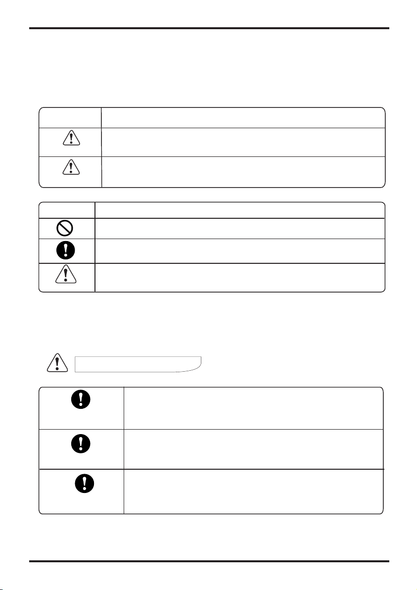
Icon Meaning
A wrong operation may lead to serious injury or death.
A wrong operation may lead to injury or loss of material.
WARNING
INSTALLATION WARNING
Icon Meaning
Compulsory - The listed action must be implemented.
Attention to what is indicated.
Prohibited (Next to this icon)
The heat pump must be installed by qualified personnel. Improper
installation could result in electrical shock /water leakage or fire.
Please ensure that the unit and power connections have a good
earth. Fail to do this may cause an electrical shock.
Professional installer
required
Earthing is required
ATTENTION
Check drainage fittings
Before installation, make sure there are no leakages on the
drainage fittings.
1.Safety Precautions
2
Installation place
Fixing the unit
Circuit breaker required
The unit CANNOT be installed near flammable gas.
Ensure that the base you are fixing to is level and strong enough.
This unit requires a circuit breaker. failure to do so could result in an
electrical shock or fire.
OPERATION WARNING
Prohibited
Shut off the power
Do not put fingers or any other objects into the fans. Children should be
kept clear of this appliance.
In the event of a unit malfunction please shut the power off and contact your service
engineer.
MOVE AND REPAIR
Important
If the heat pump needs to be relocated or installed again, only use an authorised
dealer or qualified persons.
It is prohibited for the end user to repair the unit themselves, unless qualified. failure
to do so may lead to serious injury or, and damage to the unit.
Should the heat pump need to be repaired, only use an authorised dealer or
qualified persons.
Prohibited
Important
OPERATION ATTENTION
Shut off the power
Turn the power off before cleaning the unit.
USAGE WARNING
Usage warning
Danger - High temperature.
Set a too high temperatu re of outlet water can cause scalding!
If the product need repair, please do not attempt to repair by yourself.
Inform the local vendors and send the barcode on the casing of the unit
order to reach professional repair.
1
1.Safety Precautions
To prevent personal injury and avoid causing damage to the unit, please take the time to
read the information documented in this manual.
Icon Meaning
A wrong operation may lead to serious injury or death.
A wrong operation may lead to injury or loss of material.
WARNING
INSTALLATION WARNING
Icon Meaning
Compulsory - The listed action must be implemented.
Attention to what is indicated.
Prohibited (Next to this icon)
The heat pump must be installed by qualified persons. Improper
installation could result in electrical shock /water leakage or fire.
Please ensure that the unit and power connections have a good
earth. Failure to do this may cause an electrical shock.
Professional installer
required
Earthing is required
ATTENTION
Check drainage fittings
Before installation, make sure there are no leakages on the
drainage fittings.
1.Safety Precautions
2
Installation place
Fixing the unit
Circuit breaker required
The unit CANNOT be installed near flammable gas.
Ensure that the base you are fixing to is level and strong enough.
This unit requires a circuit breaker. failure to do so could result in an
electrical shock or fire.
OPERATION WARNING
Prohibited
Shut off the power
Do not put fingers or any other objects into the fans. Children should be
kept clear of this appliance.
In the event of a unit malfunction please shut the power off and contact your
service engineer.
MOVE AND REPAIR
Important
If the heat pump needs to be relocated or installed again, only use an authorised
dealer or qualified personnel.
It is prohibited for the end user to repair the unit themselves, unless qualified. fail to do so
may lead to serious injury or/and damage to the unit.
Should the heat pump need to be repaired, only use an authorised dealer or
qualified persons.
Prohibited
Important
OPERATION ATTENTION
Shut off the power
Turn the power off before cleaning the unit.
USAGE WARNING
Usage warning
Danger - High temperature.
Setting a too high temperature of outlet water can cause scalding!
If the product need repair, please do not attempt to repair it by yourself.
Inform the local vendors and send the barcode on the casing of the unit
order to reach professional repair.

2.Specifications
3
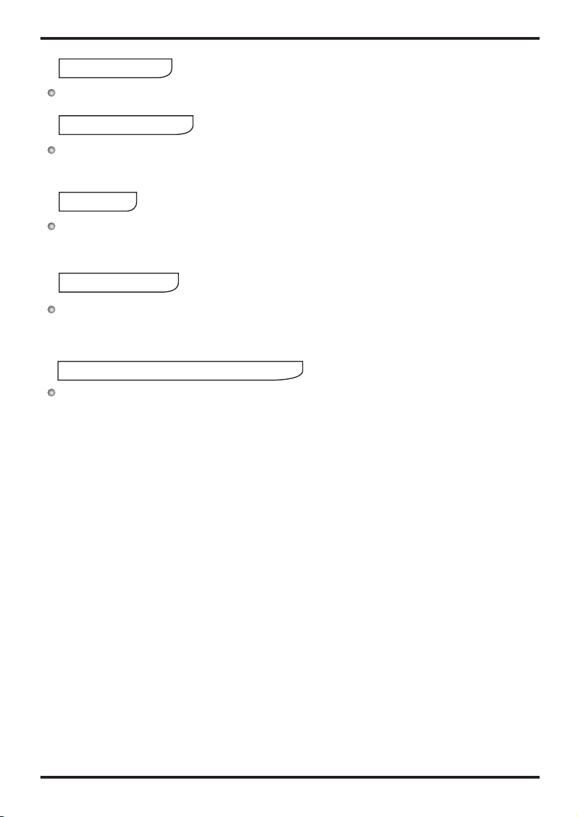
2.1 Appearance
Smart and efficient unit
The operational costs can be up to 75% less than that of an electric water heater, and can
be installed in locations which are unsuitable for solar hot water heating.
2.2 Characteristics
Easy to operate
Featuring an easy-to-use timer for both start and stop operations, with a controller to set
the desired water temperature.
Safe and environmentally friendly
Produces no harmful gases along with no open flame, making the unit safe to work with
when installing.
2. Specifications
2.3 Principal
4
Air from
outside
Hot water
Low temp.
Compressor
Compressor
Water supply
Tank
Air
exchanger Water
exchanger
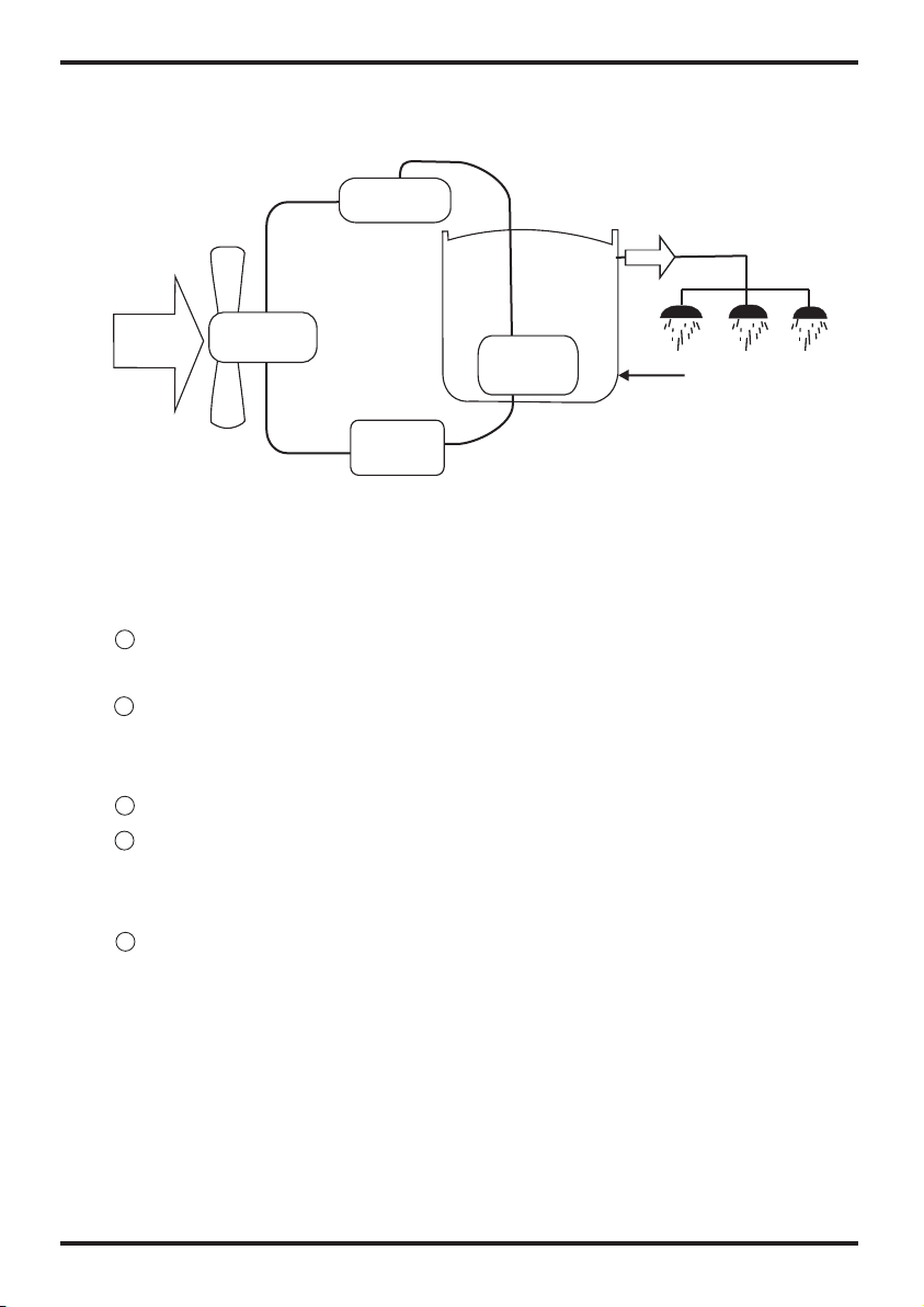
1Refrigerant is compressed into vapor with high temperature and high pressure when
it goes through the compressor.
On the discharge side of the compressor, the now hot and highly pressurized vapor
is cooled down through the heat exchange with the water in the tank until it
condenses into a high pressure, moderate temperature liquid.
Then the pressure of the liqiud refrigerant drops as it passes throttling device.
Finally, refrigerant absorbs heat from the surrounding air and evaporates into
vapor with low temperature and low pressure and then it goes into compressor
again.
The cooled surrounding air could be blew to the rooms which needs fresh cooled air.
2
3
4
5
System Principle:
Air inlet
Air outlet
Controller
Tank
Throttling
device
High temp.
2.Specifications
3
2.1 Appearance
Smart and efficient unit
The operational costs can be up to 75% less than that of an electric water heater, and can
be installed in locations which are unsuitable for solar hot water heating.
2.2 Characteristics
Easy to operate
Featuring an easy to use timer for both start and stop operations, with a controller to set the
desired water temperature.
Safe and environmentally friendly
Produces no harmful gases along with no open flame, making the unit safe to work with
when installing.
2. Specifications
2.3 Principal
4
Air from
outside
Hot water
Low temp.
Compressor
Compressor
Water supply
Water tank
Air
exchanger Heat
exchanger
1Refrigerant is compressed into vapor with high temperature and high pressure when
it goes through the compressor.
On the discharge side of the compressor, the now hot and highly pressurized vapor
is cooled down through the heat exchanger with the water in the tank until it
condenses into a high pressure, moderate temperature liquid.
Then the pressure of the liqiud refrigerant drops as it passes throttling device.
Finally, refrigerant absorbs heat from the surrounding air and evaporates into
vapor with low temperature and low pressure and then it goes into compressor
again.
The cooled surrounding air could be blew to the rooms which needs fresh cooled air.
2
3
4
5
System Principle:
Air inlet
Air outlet
controller
tank
Throttling
device
High temp.

Model
Heating capacity
Water tank capacity
Power input
Running current
Power supply
Compressor Number
Compressor
Rated outlet water Temp.
Nosie
Water inlet/outlet size
*Auxiliary E-heater
Net dimensions
Shipping dimensions
Net weight
kW
kW
A
dB(A)
inch
kW
mm
mm
kg
ATMOS AIR 180
1.7
180
0.43
1.8
240V~/50Hz
1
rotary
60
See nameplate
3/4
1.5
See the drawing of the units
See package label
See nameplate
2. Specifications
5
2.4 dimensions
2. Specifications
2.5 performance parameters
6
Work range
(1).Ambient temperature is -5℃~43℃(Heat Pump)
Measurement conditions:
Instant heating: Ambient temperature20℃/15℃,Water inlet 15℃, Water outlet 55
℃
Operating parameters
The range of the operating water pressures: 0.15~0.7MPa
Unit:mm
MODEL: ATMOS AIR 180
FREEZE PROTECTION
The water heater has a freeze protection system. The freeze protection
system will protect thewater heater from damage, by preventing ice
forming in the waterways of the water heater, in the event of freezing
conditions occurring.
16.5
1944.5
1277
Cold water
inlet
Hot water
outlet
Condensation
water outlet
Magnesium
Over heating
protector
Electric heater
Drainpipe
99 1177
1464.5
L
P&T valve
540Φ
3.Function presentation
3 minutes protection
If the unit stops and you restart the unit or turn it on by the manual switch, the unit will not start
to run again for approx 3 minutes. This is a protection feature to safe guard the compressor.
In low ambient conditions the heating output decreases.
Heating capacity
Working conditions
Defrosting
In the heating mode the unit will defrost automatically, maximizing the heating efficiency
(Lasting 2 - 10 minutes).
The fan motor will stop running whilst the unit is defrosting.
Water pressure protectiontemperature or
8
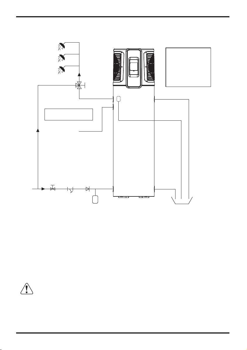
4.1 Pipeline connection sketch
4. Installation
Y-shaped Filter
7
In order to use the unit correctly, please run the unit at environment temperature
-5℃~43℃. The unit includes sophisticated electronic devices, prohibited to use water
from lake, untreated river water and groundwater!
Setup cannot affect the building structure and safety.
Notice:
A pressure realeasing
valve isto be fitted in
the installation.
Spec of P&T valve.
Pressure: 0.85MPa
Temperature: 99℃
Notice:
Tempering valve required
Water Outlet
Water Inlet
Tap Water
Thermal expansion tank
(if required)
Magnesium
Condensate Outlet
Drainpipe
Barrel-drain
P&T valve
When the tank pressure reaches 0.85MPa or when the tank temperature reach 99
℃, the P&T valve will open automatically so as to release the pressure or decrease
the temperature.
ATTENTION
Pipeline connection explanation
Installation of the water inlet or outlet pipes: The specification of the water inlet and
outlet thread is BSP3/4(internal thread).pipes must be heat-resistant and durable.
Installation of the pipe for P&T valve: The spec of the valve connecting thread is
BSP3/4(internal thread).After installation, it must be confirmed that the drainpipe
outlet is exposed in the air. drainpipe is joined to the pressure
relief orifice of this valve, you must ensure that the flexble drainpipe
and exposed in the air.
When the flexible
is pointing
downwards
ATTENTION: The Pressure release valve attached with the unit must be installed,
will cause damage to the unit, .failure to do so and possible personal injury
Do not use stainless steel fittings to connect directly with other metals to prevent
galvanic corrosion.
Drain the watertank through thedrain valve atthe bottom partof the unit.
3.Function presentation
3 minutes protection
If the unit stops and you re start the unit or turn it on by the manual switch, the unit will not
start to run again for approx 3 minutes. This is a protection feature to safe guard the
compressor.
In low ambient conditions the heating output decreases.
Heating capacity
Working conditions
Defrosting
In the heating mode the unit will defrost automatically, maximizing the heating efficiency
(Lasting 2 - 10 minutes).
The fan motor will stop running whilst the unit is defrosting.
Water pressure protectiontemperature or
8
4.1 Pipeline connection sketch
4. Installation
Y-shaped Filter
7
In order to use the unit correctly, please run the unit at environment temperature
-5℃~43℃. The unit includes sophisticated electronic devices, prohibited to use water
from lake, untreated river water and groundwater!
Setup cannot affect the building structure and safety.
Notice:
A pressure realeasing
valve is to be fitted in
the installation.
Spec of P&T valve.
Pressure: 0.85MPa
Temperature: 99℃
Notice:
Tempering valve required
Water Outlet
Water Inlet
Tap Water
Thermal expansion tank
(if required)
Magnesium
Condensate Outlet
Drainpipe
Barrel-drain
P&T valve
When the tank pressure reaches 0.85MPa, the Pressure release valve will open
automatically so as to decrease the pressure .
ATTENTION
Pipeline connection explanation
Installation of the water inlet or outlet pipes: The specification of the water inlet and
outlet thread is BSP3/4(internal thread).pipes must be heat-resistant and durable.
Installation of the pipe for P&T valve: The spec of the valve connecting thread is
BSP3/4(internal thread). After installation, it must be confirmed that the drainpipe outlet
is exposed in the air. When the flexible drainpipe is joined to the pressure relief orifice
of this valve, you must ensure that the flexible drainpipe is pointing downwards and
exposed in the air.
ATTENTION: The Pressure release valve attached with the unit must be installed, fail to
do so will cause damage to the unit, and possible personal injury.
Do not use stainless steel fittings to connect directly with other metals to prevent
galvanic corrosion.
Drain the water tank through the drain valve at the bottom part of the unit.

9
4. Installation
4.2
As a rule, the unit is to be stored and/or transported in its shipping container in the upright
position and without water charge. For transport over short distance, and provided due care is
exercised, an inclination angle of up to 30 degree is permitted. Both during transport and
storage, ambient temperatures of -5 to 43 are permissible.
4.2.1 Transport using a fork lift
When transported by a fork lift, the unit must remain mounted on the pallet. The lifting rate
should be kept to a minimum. Due to its top-heaviness, the unit must be secured against
tipping over. To prevent any damage, the unit must be placed on a level surface!
4.2.2 Manual transport
For the manual transport, the wooden pallet can be used for bottom part.
Using ropes or carrying straps, a second or third handling configuration is possible. With this
type of handling, care must be taken.
Permissible inclination angle of 60 degree is not exceeded. If transport in an inclined
position cannot be avoided, the unit should be placed into operation one hour after it has been
moved into final position.
Transportation
℃ ℃
CAUTION High center of gravity!
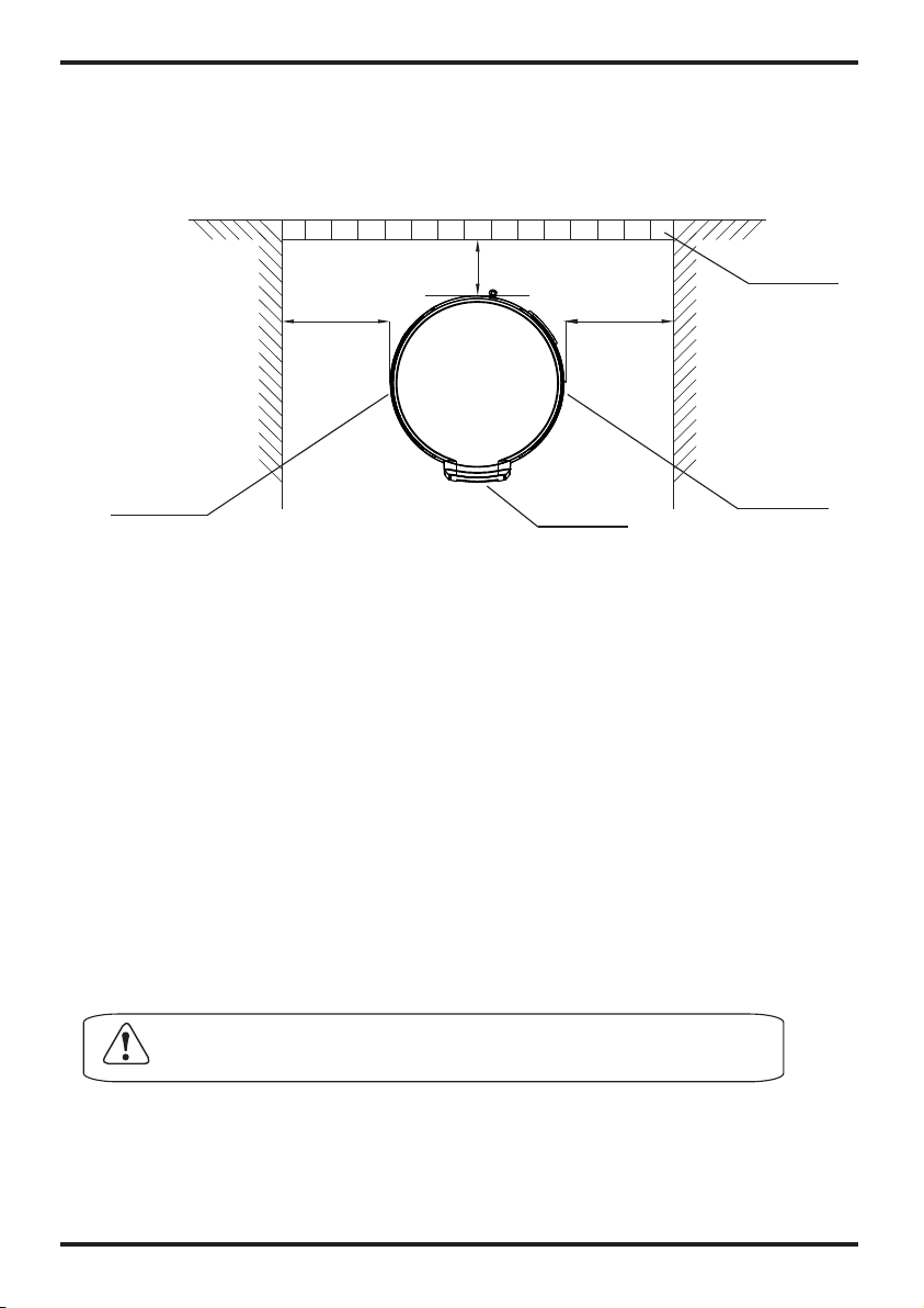
4. Installation
4.3 Installation space
Before installation, please ensure that you leave the space as shown below for maintenance.
Unit:mm
WARNING
For continued safety of this appliance it must be installed, operated and maintained in
accordance with the manufacturer's instructions.
If the water supply pressure exceeds the rated pressure, a pressure reducing valve is
tube fitted when installing the unit.
The water may drip from the discharge pipe of the pressure relief device and that
this pipe must be left open to the atmosphere.
The pressure relief device should be operated regularly to remove lime deposits
and verify that it is not blocked.
A discharge pipe connected to the pressure relief device is to be installed in a
continuously downward direction and in a frost-free environment.
Facilities ford raining and filling of systems shall be provided where these a
required for servicing purposes. The drainage facilities, where fitted, shall beat the
lowest point in the closed circuit.
CAUTION :The minimum space of installation is 10 cubic meter.
10
Air inlet
Air outlet Display
Barrier
500≥1000≥
≥300
9
4. Installation
4.2
As a rule, the unit is to be stored and/or transported in its shipping container in the upright
position and without water charge. For transport over short distance, and provided due care is
exercised, an inclination angle of up to 30 degree is permitted. Both during transport and
storage, ambient temperatures of -5 to 43 are permissible.
4.2.1 Transport using a forklift
When transported by a fork lift, the unit must remain mounted on the pallet. The lifting rate
should be kept to a minimum. Due to its top-heaviness, the unit must be secured against
tipping over. To prevent any damage, the unit must be placed on a level surface!
4.2.2 Manual transport
For the manual transport, the wooden pallet can be used for bottom part.
Using ropes or carrying straps, a second or third handling configuration is possible. With this
type of handling, care must be taken that the max.
Permissible inclination angle of 60 degree is not exceeded. If transport in an inclined
position cannot be avoided, the unit should be placed into operation one hour after it has been
moved into final position.
Transportation
℃ ℃
CAUTION High center of gravity!
4. Installation
4.3 Installation space
Before installation, please ensure that you leave the space as shown below for maintenance.
Unit:mm
WARNING
For continued safety of this appliance it mst be installed, operated and
maintained in accordance with the manufacturer's instructions.
If the water supply pressure exceeds the rated pressure, a pressure reducing
valve is tube fitted when installing the unit.
The water may drip from the discharge pipe of the pressure relief device and that
this pipe must be left open to the atmosphere.
The pressure relief device should be operated regularly to remove lime deposits
and verify that it is not blocked.
A discharge pipe connected to the pressure relief device is to be installed in a
continuously downward direction and in a frost-free environment.
Facilities ford raining and filling of systems shall be provided where these a
required for servicing purposes. The drainage facilities, where fitted, shall beat the
lowest point in the closed circuit.
CAUTION :The minimum space of installation is 10 cubic meter.
10
Air inlet
Air outlet Display
Barrier
500≥ 1000≥
≥300
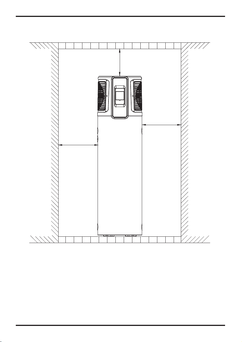
11
4. Installation 4.Installation
12
4.4 Cable connection
4.5 Trial running
This unit requires an isolating switch as required by local by laws.
4.5.1 Inspection before trial running
Check the water supply to the tank and pipe connections for possible leaks.
Check that all power connections are secure before switching on.
4.5.2 Trial running
Switch on the unit using the controller
In the case of any unusual noise, switch the power off and consult your provider;
If the power cord is damaged, It must be replaced by a qualified electrician.
The parameters have been pre set to a temperature of 60 degrees.
Unit:mm
4.6 Seismic restraints
The unit must be braced with with seismic restraints according to local by laws.
1000≥
500≥
600≥

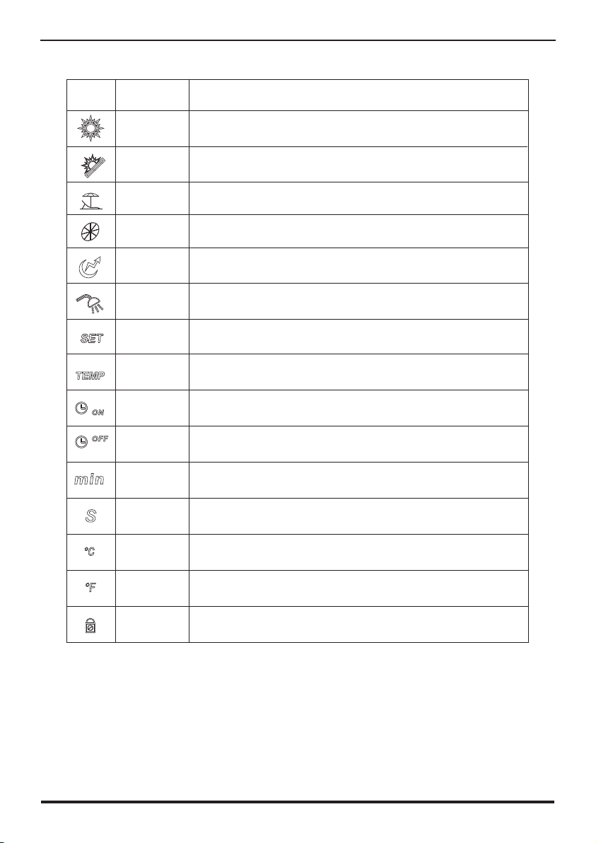
13 14
5.Usage
Electric
heater
Fan
Shows that the electric heater is on.
Shows that the fan is on and the speed of the fan.
Set temperature
achieved
Shows that the water temperature has reached the target
point and the unit shut off automatically.
Timer & ON
Timer & OFF Shows that the unit will be turned off by the timer
automatically.
Shows that the unit will be turned on by the timer
automatically.
Minute Shows that the main display area displays the minute.
Second Shows that the main display area displays the second.
Centigrade
Fahrenheit
Parameter
setting Shows that the parameter is adjustable.
Lock Shows that the keyboard is locked.
Status
icon What it means
Heating
Vacation
Shows that the unit is in heating mode.
Shows that the unit is in vacation mode.
Eco.heating
Temperature Shows that the temperature is non-adjustable
(measured value).
Name
Shows that the unit is in e mode.co.heating
5.Usage
5.1 The function diagram of the wire controller
1.Function of wire controller
NO. Button Name Function
1
2
3
4
5
6
ON/OFF
Mode
Electric
Heater
Up
Down
Turn on/off the unit.
Switch unit running modes or save setting parameters.
Set the clock or the timer.
Turn on/off the electric heater or switch fan modes.
Move up or increase parameter values.
Move down or decrease parameter values.
Clock
Main display
area
Auxiliary display
area
1 2 3 4 5 6
Shows that the temperature in Main display area or Auxiliary
display area is in ℉.
Shows that the temperature in Main display area or Auxiliary
display area is in ℃.

15
5.Usage
16
5.Usage
5.2 Usage of wire controller
Outlet water temperature
Press " " and hold for 0.5s.
Inlet water
temperature
Heating mode
Standby interface
5.2.2 Mode selection
Press " " to select the mode from Heating ,Eco.heating ,Vacation, , High
requirement in the standby or running interface.
For example:
Intelligent
Running interface
5.2.1 Turn ON/OFF the unit
Press " " and hold for 0.5s in the standby interface of the wire controller to turn on the
unit and at this time the main display area shows the water outlet temperature.
Press " " and hold for 0.5s in the running interface of the wire controller to turn off the
unit and at this time the main display area shows OFF.
Note: The ON/OFF button can only be used to turn on/off the unit in standby or running
interface of the wire controller.
5.2.3 Target temperature checking and setting
In the standby or running interface, press " " or " " once to check the target temperature
of the outlet water. Press " " or " " again to change the target temperature. After making
the changes to the parameter, press " " to confirm or " " to cancel the changes, then
return to the previous interface. If no operations are performed on the keypad for 5s, the
controller exits the parameter modification menu by timeout and the changes are confirmed.
Setting 75 : " "
°" "
°C When the target temperature is adjusted to 60 °C, press and hold the for
5s. At this time, the target temperature is displayed as 61 °C and the temperature range
changed to 38-75 C. Press the to set the target temperature to 75 °C.
Example: Change the target temperature from 55°C to 70°C when the actual outlet water
temper is 18°C.
Press“ ”
Press“ ”
Press“ ”
Heating mode
Outlet water
temperature
Time Eco.heating mode
Vacation mode
Date
modeIntelligent
Press“ ” High requirement mode

15
5.Usage
16
5.Usage
5.2 Usage of wire controller
Outlet water temperature
Press " " and hold for 0.5s.
Inlet water
temperature
Heating mode
Standby interface
5.2.2 Mode selection
Press " " to select the mode from Heating ,Eco.heating ,Vacation, , High
requirement in the standby or running interface.
For example:
Intelligent
Running interface
5.2.1 Turn ON/OFF the unit
Press " " and hold for 0.5s in the standby interface of the wire controller to turn on the
unit and at this time the main display area shows the water outlet temperature.
Press " " and hold for 0.5s in the running interface of the wire controller to turn off the
unit and at this time the main display area shows OFF.
Note: The ON/OFF button can only be used to turn on/off the unit in standby or running
interface of the wire controller.
5.2.3 Target temperature checking and setting
In the standby or running interface, press " " or " " once to check the target temperature
of the outlet water. Press " " or " " again to change the target temperature. After making
the changes to the parameter, press " " to confirm or " " to cancel the changes, then
return to the previous interface. If no operations are performed on the keypad for 5s, the
controller exits the parameter modification menu by timeout and the changes are confirmed.
Setting 75°C: When the target temperature is adjusted to 60 °C, press and hold the" " for
5s. At this time, the target temperature is displayed as 61 °C and the temperature range
changed to 38-75°C. Press the" " to set the target temperature to 75 °C.
Example: Change the target temperature from 55°C to 70°C when the actual outlet water temperature
is 18°C.
Press“ ”
Press“ ”
Press“ ”
Heating mode
Outlet water
temperature
Time Eco.heating mode
Vacation mode
Date
modeIntelligent
Press“ ”High requirement mode

5.Usage
17
Outlet water temperature
Time
Target temperature
Press and hold the for 5s ,then press
or again to change the target
temperature.
Press
to confirm
or to
cancel, then
return to the
previous
interface.
Press
to change the
target
temperature
from 55℃ to
60℃.
5.2.4 Time setting
In the standby or running interface, do as follows to set the time when in heating mode. When
press " " once, the time parameter will flash. When press " " again, the hour parameter
will flash then press " " or " " to change it. After making the changes to the parameter,
press" " to confirm, then change the minute parameter as well as the date parameter in the
same way.
If no operations are performed on the keypad for 15s, the controller exits the parameter
modification menu by timeout and the changes are confirmed.
Note: Set the date in the same way when in vacation mode.
Example: Change the time and date from 18:30 on August 4th to 17:40 on September 8th.
Time
Press
twice then
press or
to change
the hour
parameter
and press
to confirm.
Press " " or " " to change the minute
parameter.
5. Usage
18
The new set time
Press " " to confirm.
Press " " or " " to change the minute
parameter.
The date is flashing
Press once then press or to change
the month parameter and press to confirm.
Press " " or
" " to change
the day parameter.
Press" "
to confirm.
5.2.5 Timer setting
5.2.5.1 Under the standard mode, economic mode, intelligent mode, you can enter the timer
setting.
Press " " and hold for 2s, the "ON "and " 1 " will flash, and then you can set the turn on
time of timer1 as the 24 clock setting show. After finishing, " OFF " and " 1 " will flash, that
means you can set the turn off time of timer1. The "ON " and " 2 " will flash after finishing the
timer1 setting, you can set the turn on time of timer2. After finishing, the " OFF " and " 2 " will
flash, and then you can set the turn off time of timer2. Press " " again to save and back to
the interface. If you don't need to set the timer2, you can press the " " to save after finishing
the timer1 setting. You will find the " ON " and " 2 " flash. No operation for 5s, the program will
back to the interface automatically.
Note: When press " " and hold for 2s, the " ON " and " 1 " will flash. It is not necessary for
you to set the turn on time of the timer1. You can sequentially to press " " for 2s to enter to
the turn off time of timer1. So does the timer2. Or press " " or " " to circularly display.
Timer Cancel: Press " " and hold for 2s to enter into the interface, and then press " "
to cancel all the operation. Please see the following picture for more details.
Table of contents
Other Solahart Heat Pump manuals


Popular Heat Pump manuals by other brands

Trane
Trane 4WCZ6036B3000A Installation and operation manual

Viessmann
Viessmann VITOBLOC 200 Series operating instructions

Fedders
Fedders CH1042CBD1VF Specification sheet

Zodiac
Zodiac Z250 MD3 Instructions for installation and use

STIEBEL ELTRON
STIEBEL ELTRON SHP-A 220 Plus Operation and installation

DeLonghi
DeLonghi Bran 0011M H Installation, operating & service instructions


Nova Booster
Nova Booster Swimming Pool Heat Pump User & service manual

Electra
Electra PXD 25 DCI Service manual

Danfoss
Danfoss BW10 020-090 Operation instructions

TLV
TLV J10 instruction manual

Samsung
Samsung HHSM-G500005-1 installation manual

Nordyne
Nordyne Q5RD Series User's manual & installation instructions