Solahart AtmosAir 180 User manual

Operation &Installation ManualOperation &Installation Manual
HEATPUMPHEATPUMP

Preface
This manual couldbe subject tochange without priornotice, if itis felt thatproduct
improvements are tobe carried out.
When Installing the hot water cylinder, please follow the Instructions as documented in this manual.
A maintenanceprogramme must becarried out asrecommended in thismanual.
Failure to complywith these recommendationswill invalidate the warranty.
It is importantthat the installationand operational instructionslaid out inthis manual are
strictly adhered to.
This manual includesall the necessaryinformation regarding theInstallation and
maintenance of thisproduct. Please takethe time toread it throughbefore operating.
Once the Installation is complete, check that all connections are secure before the power is turned
On.
The installer is to explain to the end user how to operate and maintain the unit in accordance to this
Instruction manual.
Content
Content
1. Safety Precautions
1
2. Specifications
3
2.1) appearance
3
2.2) characteristic
3
2.3) principle
4
2.4) dimensions
5
2.5) performance parameter
6
3. Function presentation
7
4. Installation
8
4.1) pipeline connection sketch
8
4.2) transportation
9
4.3) installation space
10
4.4) cable connection
12
4.5) trial running
12
5. Usage
13
5.1) function of wire controller
13
5.2) usage of wire controller
15
6. Maintenance and repair
25
7. Appendix
27
6.2) trouble shooting guide
25
6.1) maintenance
25
4.6) seismic restraints
12
27
28
7.1)caution
28
7.2)the method of grounding
29
7.3)use of the Pressure release valve
7.4)drain outthe waterin the storage tank
If the supplycord is damaged,it must bereplaced by themanufacturer, itsservice agentor
similarly qualified personsin order toavoid a hazard.
This appliance isnot intended foruse by persons(including children) withreduced physical,
sensory or mentalcapabilities, or lackof experience andknowledge, unless theyhave
been given supervisionor instruction concerninguse of theappliance by aperson
responsible for theirsafety.
Children should besupervised to ensurethat they donot play withthe appliance.
29
7.5)use of the overheating protector
1
1.Safety Precautions
Toprevent personal injuryand avoid causingdamage to theunit, please takethe time to
read the informationdocumented in thismanual.
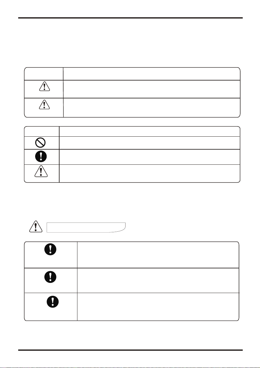
Icon Meaning
Awrong operation maylead to seriousinjury or death.
A wrongoperation may leadto injury orloss of material.
WARNING
INSTALLATION WARNING
Icon Meaning
Compulsory -The listed actionmust be implemented.
Attention to whatis indicated.
Prohibited (Next tothis icon)
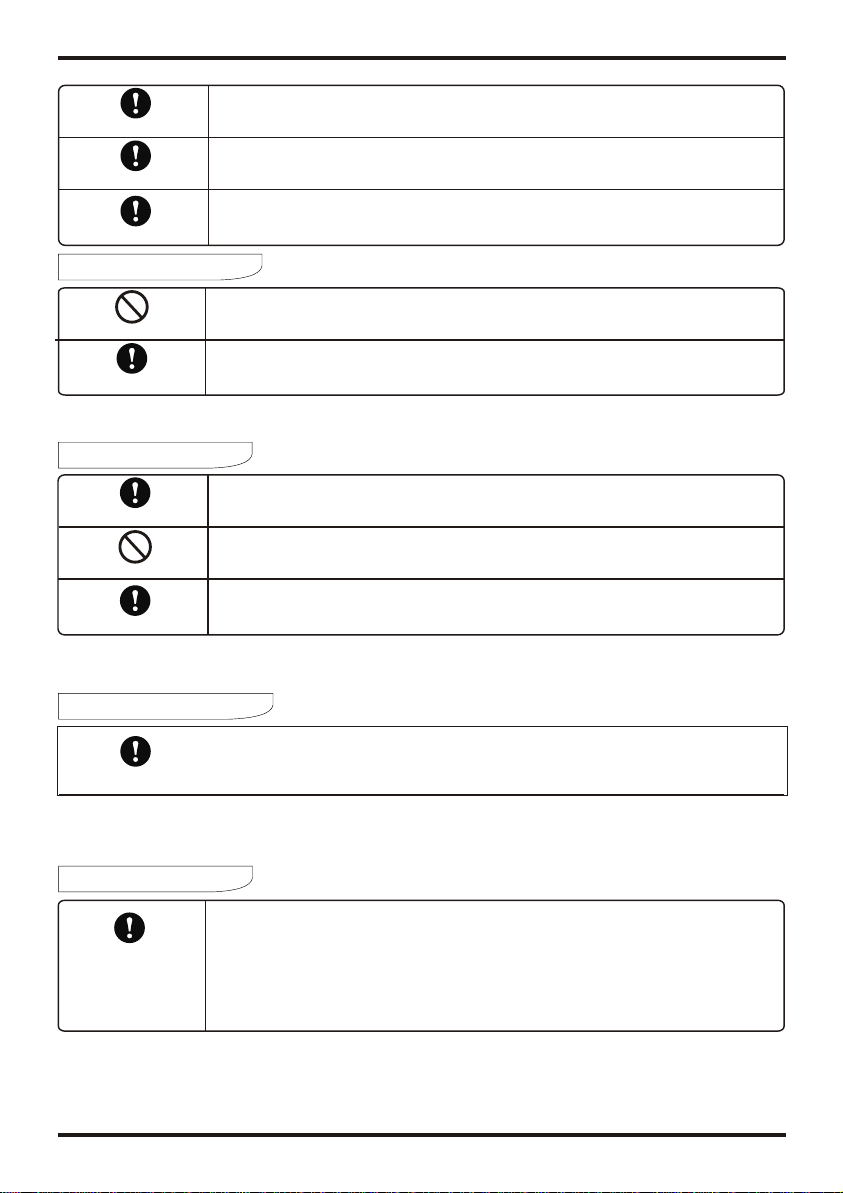
The heat pumpmust be installedby qualified persons.Improper
installation could resultin electrical shock/water leakage orfire.
Please ensure thatthe unit andpower connections havea good
earth. Failure todo this maycause an electricalshock.
Professional installer
required
Earthing is required
ATTENTION
Check drainage fittings Before installation, makesure there areno leakages onthe
drainage fittings.
1.Safety Precautions
2
Installation place
Fixing theunit
Circuit breaker required
The unit CANNOTbe installed nearflammable gas.
Ensure that thebase you arefixing to islevel and strongenough.
This unit requiresa circuit breaker. failure todo so couldresult in an
electrical shock orfire.
OPERATIONWARNING
Prohibited
Shut off thepower
Do not putfingers or anyother objects intothe fans. Childrenshould be
kept clear ofthis appliance.
In the eventof a unitmalfunction please shutthe power offand contact yourservice
engineer.
MOVE AND REPAIR
Important
If the heatpump needs tobe relocated orinstalled again, onlyuse an authorised
dealer or qualifiedpersons.
It is prohibitedfor the enduser to repairthe unit themselves,unless qualified. failure
to do somay lead toserious injury or, and damageto the unit.
Should the heatpump need tobe repaired, onlyuse an authoriseddealer or
qualified persons.
Prohibited
Important
OPERATIONATTENTION
Shut offthe power
Turn thepower offbefore cleaning theunit.
USAGE WARNING
Usage warning
Danger - High temperature.
Set a too high temperatu re of outlet water can cause scalding!
If the product need repair, please do not attempt to repair by yourself.
Inform the local vendors and send the barcode on the casing of the unit
order to reach professional repair.
1
1.Safety Precautions
Toprevent personal injuryand avoid causingdamage to theunit, please takethe time to
read the informationdocumented in thismanual.
Icon Meaning
Awrong operation maylead to seriousinjury or death.
A wrongoperation may leadto injury orloss of material.
WARNING
INSTALLATION WARNING
Icon Meaning
Compulsory -The listed actionmust be implemented.
Attention to whatis indicated.
Prohibited (Next tothis icon)
The heat pumpmust be installedby qualified persons.Improper
installation could resultin electrical shock/water leakage orfire.
Please ensure thatthe unit andpower connections havea good
earth. Failure todo this maycause an electricalshock.
Professional installer
required
Earthing is required
ATTENTION
Check drainage fittings Before installation, makesure there areno leakages onthe
drainage fittings.
1.Safety Precautions
2
Installation place
Fixing theunit
Circuit breaker required
The unit CANNOTbe installed nearflammable gas.
Ensure that thebase you arefixing to islevel and strongenough.
This unit requiresa circuit breaker. failure todo so couldresult in an
electrical shock orfire.
OPERATIONWARNING
Prohibited
Shut off thepower
Do not putfingers or anyother objects intothe fans. Childrenshould be
kept clear ofthis appliance.
In the eventof a unitmalfunction please shutthe power offand contact yourservice
engineer.
MOVE AND REPAIR
Important
If the heatpump needs tobe relocated orinstalled again, onlyuse an authorised
dealer or qualifiedpersons.
It is prohibitedfor the enduser to repairthe unit themselves,unless qualified. failure
to do somay lead toserious injury or, and damageto the unit.
Should the heatpump need tobe repaired, onlyuse an authoriseddealer or
qualified persons.
Prohibited
Important
OPERATIONATTENTION
Shut offthe power
Turn thepower offbefore cleaning theunit.
USAGE WARNING
Usage warning
Danger - High temperature.
Set a too high temperatu re of outlet water can cause scalding!
If the product need repair, please do not attempt to repair by yourself.
Inform the local vendors and send the barcode on the casing of the unit
order to reach professional repair.

2.Specifications
3
2.1 Appearance
Smart and efficient unit
The operational costs can be up to 75% less than that of an electric water heater, and can
be installed in locations which are unsuitable for solar hot water heating.
2.2 Characteristics
Easy to operate
Featuring an easy to use timer for both start and stop operations, with a controller to set the
desired water temperature.
Safe and environmentally friendly
Produces no harmful gases along with no open flame, making the unit safe to work with
when installing.
2. Specifications
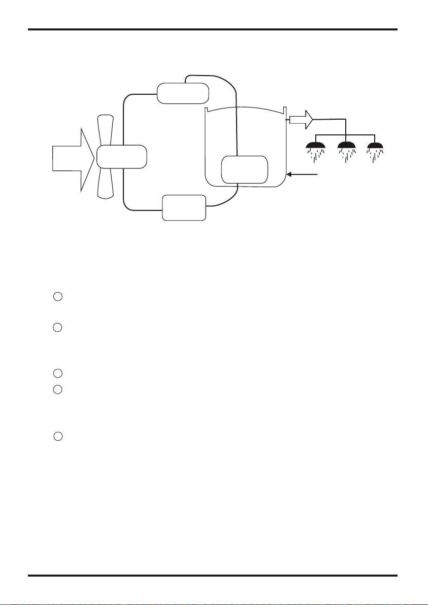
2.3 Principal
4
Air from
outside
Hot water
Low temp.
Compressor
Compressor
Water supply
Tank
Air
exchanger Water
exchanger
1Refrigerant is compressed into vapor with high temperature and high pressure when
it goes through the compressor.
On the discharge side of the compressor, the now hot and highly pressurized vapor
is cooled down through the heat exchange with the water in the tank until it
condenses into a high pressure, moderate temperature liquid.
Then the pressure of the liqiud refrigerant drops as it passes throttling device.
Finally, refrigerant absorbs heat from the surrounding air and evaporates into
vapor with low temperature and low pressure and then it goes into compressor
again.
The cooled surrounding air could be blew to the rooms which needs fresh cooled air.
2
3
4
5
System Principle:
Air inlet
Air outlet
controller
tank
Throttling
device
High temp.
2.Specifications
3
2.1 Appearance
Smart and efficient unit
The operational costs can be up to 75% less than that of an electric water heater, and can
be installed in locations which are unsuitable for solar hot water heating.
2.2 Characteristics
Easy to operate
Featuring an easy to use timer for both start and stop operations, with a controller to set the
desired water temperature.
Safe and environmentally friendly
Produces no harmful gases along with no open flame, making the unit safe to work with
when installing.
2. Specifications
2.3 Principal
4
Air from
outside
Hot water
Low temp.
Compressor
Compressor
Water supply
Tank
Air
exchanger Water
exchanger
1Refrigerant is compressed into vapor with high temperature and high pressure when
it goes through the compressor.
On the discharge side of the compressor, the now hot and highly pressurized vapor
is cooled down through the heat exchange with the water in the tank until it
condenses into a high pressure, moderate temperature liquid.
Then the pressure of the liqiud refrigerant drops as it passes throttling device.
Finally, refrigerant absorbs heat from the surrounding air and evaporates into
vapor with low temperature and low pressure and then it goes into compressor
again.
The cooled surrounding air could be blew to the rooms which needs fresh cooled air.
2
3
4
5
System Principle:
Air inlet
Air outlet
controller
tank
Throttling
device
High temp.
Model
Heating capacity
Water tankcapacity
Power input
Running current
Power supply
Compressor Number
Compressor
Rated outlet waterTemp.
Nosie
Water inlet/outletsize
*Auxiliary E-heater
Net dimensions
Shipping dimensions
Net weight
Shipping weight
kW
kW
A
dB(A)
inch
kW
mm
mm
kg
kg
ATMOSAIR 180
1.7
180
0.43
1.8
240V~/50Hz
1
rotary
55
See nameplate
3/4
1.5
See the drawingof the units
See package label
See nameplate
See package label
2. Specifications
5
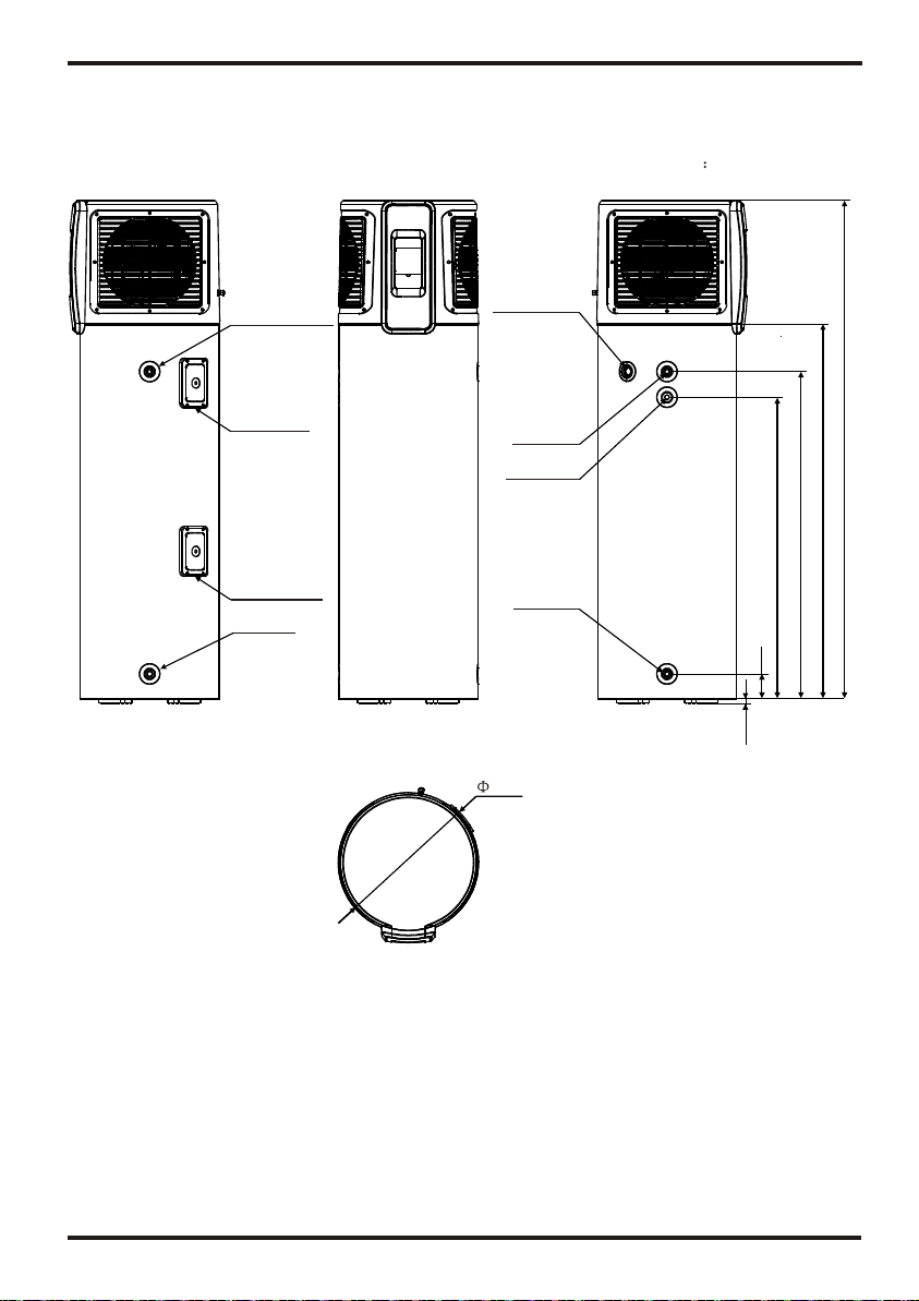
2.4 dimensions
2. Specifications
2.5 performance parameters
6
Work range
(1).Ambient temperatureis 0 ~40 (Heat Pump)
Measurement conditions:
Instant heating:Ambienttemperature20 /15 ,Water inlet15 , Wateroutlet 55
Operating parameters
The range ofthe operating waterpressures: 0.15~0.7MPa
Unit mm
MODEL: ATMOS AIR 180
FREEZE PROTECTION
The waterheater hasa freezeprotection system.The freezeprotection
system will protectthewater heater fromdamage, by preventingice
forming inthe waterwaysof thewater heater, inthe eventof freezing
conditions occurring.
16.5
1944.5
1277
Cold water
inlet
Hot water
outlet
Condensation
water outlet
Magnesium
Over heating
protector
Electric heater
Drainpipe
99 1177
1464.5
L
Pressure release
valve
540

Model
Heating capacity
Water tankcapacity
Power input
Running current
Power supply
Compressor Number
Compressor
Rated outlet waterTemp.
Nosie
Water inlet/outletsize
*Auxiliary E-heater
Net dimensions
Shipping dimensions
Net weight
Shipping weight
kW
kW
A
dB(A)
inch
kW
mm
mm
kg
kg
ATMOSAIR 180
1.7
180
0.43
1.8
240V~/50Hz
1
rotary
55
See nameplate
3/4
1.5
See the drawingof the units
See package label
See nameplate
See package label
2. Specifications
5
2.4 dimensions
2. Specifications
2.5 performance parameters
6
Work range
(1).Ambient temperatureis 0 ~40 (Heat Pump)
Measurement conditions:
Instant heating:Ambienttemperature20 /15 ,Water inlet15 , Wateroutlet 55
Operating parameters
The range ofthe operating waterpressures: 0.15~0.7MPa
Unit mm
MODEL: ATMOS AIR 180
FREEZE PROTECTION
The waterheater hasa freezeprotection system.The freezeprotection
system will protectthewater heater fromdamage, by preventingice
forming inthe waterwaysof thewater heater, inthe eventof freezing
conditions occurring.
16.5
1944.5
1277
Cold water
inlet
Hot water
outlet
Condensation
water outlet
Magnesium
Over heating
protector
Electric heater
Drainpipe
99 1177
1464.5
L
Pressure release
valve
540

3.Function presentation
3 minutes protection
If the unitstops and youre start theunit or turnit on bythe manual switch,the unit willnot
start to runagain for approx3 minutes.This is aprotection feature tosafe guard the
compressor.
In low ambientconditions the heatingoutput decreases.
Heating capacity
Working conditions
Defrosting
In the heatingmode the unitwill defrost automatically, maximizing theheating efficiency
(Lasting 2 -10 minutes).
The fan motorwill stop runningwhilst the unitis defrosting.
Water pressure protectiontemperature or
8
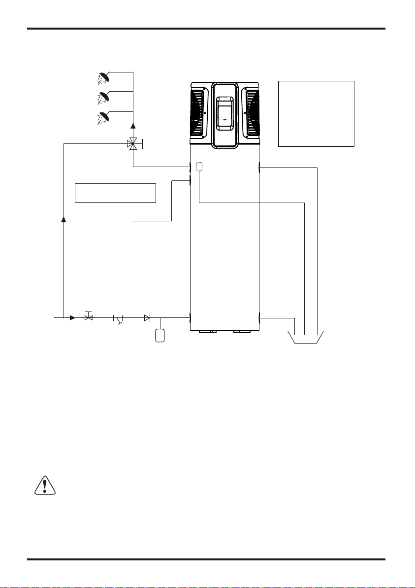
4.1 Pipeline connectionsketch
4. Installation
Y-shaped Filter
7
In order touse the unitcorrectly,please run theunit at environmenttemperature
0 ~40 . Theunit includes sophisticatedelectronic devices, prohibitedto use water
from lake, untreatedriver water andgroundwater!
Setup cannotaffect thebuilding structureand safety.
Notice:
A pressurerealeasing
valve isto befitted in
the installation.
Spec of Pressure
release valve:
Pressure: 0.7MPa
Notice:
Tempering valve required
Water Outlet
Water Inlet
Tap Water
Thermal expansion tank
(if required)
Magnesium
Condensate Outlet
Drainpipe
Barrel-drain
Pressure release valve
When the tankpressure reaches 0.7MPa,the Pressure release valve will open
automatically so asto decrease thepressure .
ATTENTION
Pipeline connection explanation
Installation of thewater inlet oroutlet pipes:The specification ofthe water inletand
outlet thread isBSP3/4(internal thread).pipesmust be heat-resistantand durable.
Installation of thepipe for Pressurerelease valve:The spec ofthe valve connecting
thread is BSP3/4(internal thread).After installation,it must beconfirmed that the
drainpipe outlet isexposed in theair. drainpipe is joinedto the
pressure relief orificeof this valve,you must ensure that the flexbledrainpipe
and exposed inthe air.
When the flexible is
pointing downwards
ATTENTION:The Pressurerelease valve attachedwith the unitmust be installed,
will cause damageto the unit, .failure to doso and possible personalinjury
Do not usestainless steel fittingsto connect directlywith other metalsto prevent
galvanic corrosion.
Drain the watertankthrough thedrain valveatthe bottom partofthe unit.
3.Function presentation
3 minutes protection
If the unitstops and youre start theunit or turnit on bythe manual switch,the unit willnot
start to runagain for approx3 minutes.This is aprotection feature tosafe guard the
compressor.
In low ambientconditions the heatingoutput decreases.
Heating capacity
Working conditions
Defrosting
In the heatingmode the unitwill defrost automatically, maximizing theheating efficiency
(Lasting 2 -10 minutes).
The fan motorwill stop runningwhilst the unitis defrosting.
Water pressure protectiontemperature or
8
4.1 Pipeline connectionsketch
4. Installation
Y-shaped Filter
7
In order touse the unitcorrectly,please run theunit at environmenttemperature
0 ~40 . Theunit includes sophisticatedelectronic devices, prohibitedto use water
from lake, untreatedriver water andgroundwater!
Setup cannotaffect thebuilding structureand safety.
Notice:
A pressurerealeasing
valve isto befitted in
the installation.
Spec of Pressure
release valve:
Pressure: 0.7MPa
Notice:
Tempering valve required
Water Outlet
Water Inlet
Tap Water
Thermal expansion tank
(if required)
Magnesium
Condensate Outlet
Drainpipe
Barrel-drain
Pressure release valve
When the tankpressure reaches 0.7MPa,the Pressure release valve will open
automatically so asto decrease thepressure .
ATTENTION
Pipeline connection explanation
Installation of thewater inlet oroutlet pipes:The specification ofthe water inletand
outlet thread isBSP3/4(internal thread).pipesmust be heat-resistantand durable.
Installation of thepipe for Pressurerelease valve:The spec ofthe valve connecting
thread is BSP3/4(internal thread).After installation,it must beconfirmed that the
drainpipe outlet isexposed in theair. drainpipe is joinedto the
pressure relief orificeof this valve,you must ensure that the flexbledrainpipe
and exposed inthe air.
When the flexible is
pointing downwards
ATTENTION:The Pressurerelease valve attachedwith the unitmust be installed,
will cause damageto the unit, .failure to doso and possible personalinjury
Do not usestainless steel fittingsto connect directlywith other metalsto prevent
galvanic corrosion.
Drain the watertankthrough thedrain valveatthe bottom partofthe unit.

9
4. Installation
4.2
As arule, the unitis to bestored and/or transportedin its shippingcontainer in the upright
position and withoutwater charge. Fortransport over shortdistance, and provideddue care is
exercised, an inclinationangle of upto 30 degreeis permitted. Bothduring transport and
storage, ambient temperaturesof 0 to 40 are permissible.
4.2.1 Transportusing a forklift
When transported bya fork lift,the unit mustremain mounted onthe pallet.The lifting rate
should be keptto a minimum.Due to itstop-heaviness, the unitmust be securedagainst
tipping over.To prevent anydamage, the unitmust be placedon a levelsurface!
4.2.2 Manual transport
For the manualtransport, the woodenpallet can beused for bottompart.
Using ropes orcarrying straps, asecond or thirdhandling configuration ispossible. With this
type of handling,care must betaken that themax.
Permissible inclination angleof 60 degreeis not exceeded.If transport inan inclined
position cannot beavoided, the unitshould be placedinto operation onehour after ithas been
moved into finalposition.
Transportation
CAUTION High center of gravity!
4. Installation
4.3 Installation space
Before installation, pleaseensure that youleave the spaceas shown belowfor maintenance.
Unit:mm
WARNING
For continuedsafety ofthis applianceit mstbe installed,operated and
maintained in accordancewith the manufacturer'sinstructions.
If thewater supplypressure exceedsthe ratedpressure, apressure reducing
valve is tubefitted when installingthe unit.
The watermay dripfrom thedischarge pipeof thepressure reliefdevice andthat
this pipemust beleft opento theatmosphere.
The pressurerelief device shouldbe operated regularlyto remove limedeposits
and verifythat itis notblocked.
Adischarge pipeconnected tothe pressurerelief deviceis tobe installedin a
continuously downward directionand in afrost-free environment.
Facilities ford rainingand filling ofsystems shall beprovided where thesea
required forservicing purposes.The drainagefacilities, wherefitted, shallbeat the
lowest point inthe closed circuit.
CAUTION :The minimum space of installation is 10 cubic meter.
10
Air inlet
Air outlet Display
Barrier
500 1000
300

11
4. Installation 4.Installation
12
4.4 Cable connection
4.5 Trial running
This unit requires an isolating switch as required by local by laws.
4.5.1 Inspection before trial running
Check the watersupply to thetank and pipeconnections for possibleleaks.
Check that allpower connections aresecure before switchingon.
4.5.2Trialrunning
Switch on the unit using the controller
In the caseof any unusualnoise, switch thepower offand consult yourprovider;
If the powercord is damaged,It must bereplaced by aqualified electrician.
The parameters havebeen pre setto a temperatureof 60 degrees.
Unit:mm
4.6 Seismic restraints
The unit must be braced with with seismic restraints according to local by laws.
1000
500
600

13 14
5.Usage Usage
5.1 Thefunction diagram ofthe wire controller
1.Function ofwire controller
1 Function of key
NO. Button Name Function
1
2
3
4
5
6
ON/OFF
Mode
Electric
Heater
Up
Down
Turn on/offthe unit.
Switch unit runningmodes or savesetting parameters.
Set the clockor the timer.
Turn on/offthe electric heateror switch fanmodes.
Move up orincrease parameter values.
Move down ordecrease parameter values.
Clock
Main display
area
Auxiliary display
area
123456
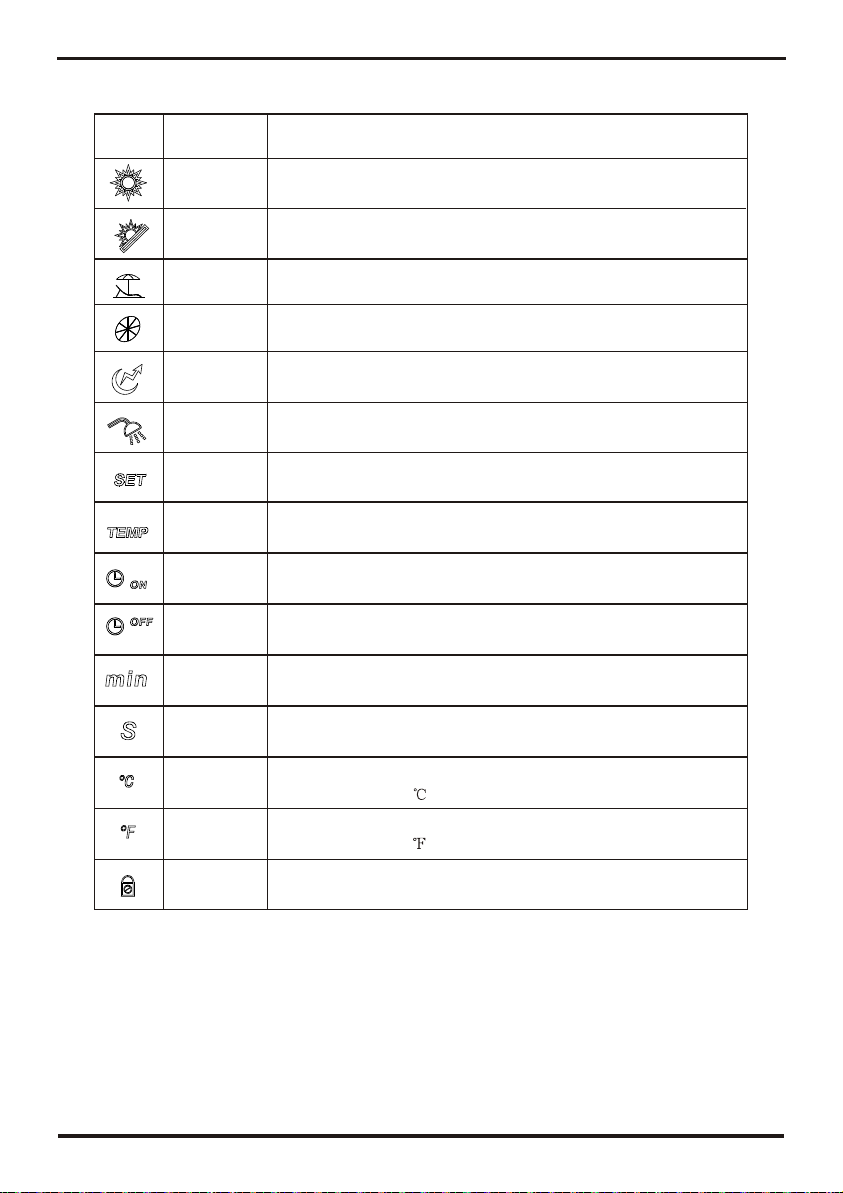
Electric
heater
Fan
Shows that theelectric heater ison.
Shows that thefan is onand the speedof the fan.
Set temperature
achieved Shows that thewater temperature hasreached the target
point and theunit shut off automatically.
Timer &ON
Timer &OFF Shows that theunit will beturned offby the timer
automatically.
Shows that theunit will beturned on bythe timer
automatically.
Minute Shows that themain display areadisplays the minute.
Second Shows that themain display areadisplays the second.
Centigrade
Fahrenheit
Parameter
setting Shows that theparameter is adjustable.
Lock Shows that thekeyboard is locked.
Status
icon What it means
Heating
Vacation
Shows that theunit is inheating mode.
Shows that theunit is invacation mode.
Eco.heating
Temperature Shows that thetemperature is non-adjustable
(measured value).
Name
Shows that theunit is ine mode.co.heating
Shows that thetemperature in Maindisplay area orAuxiliary
display area isin .
Shows that thetemperature in Maindisplay area orAuxiliary
display area isin .
13 14
5.Usage Usage
5.1 Thefunction diagram ofthe wire controller
1.Function ofwire controller
1 Function of key
NO. Button Name Function
1
2
3
4
5
6
ON/OFF
Mode
Electric
Heater
Up
Down
Turn on/offthe unit.
Switch unit runningmodes or savesetting parameters.
Set the clockor the timer.
Turn on/offthe electric heateror switch fanmodes.
Move up orincrease parameter values.
Move down ordecrease parameter values.
Clock
Main display
area
Auxiliary display
area
123456
Electric
heater
Fan
Shows that theelectric heater ison.
Shows that thefan is onand the speedof the fan.
Set temperature
achieved Shows that thewater temperature hasreached the target
point and theunit shut off automatically.
Timer &ON
Timer &OFF Shows that theunit will beturned offby the timer
automatically.
Shows that theunit will beturned on bythe timer
automatically.
Minute Shows that themain display areadisplays the minute.
Second Shows that themain display areadisplays the second.
Centigrade
Fahrenheit
Parameter
setting Shows that theparameter is adjustable.
Lock Shows that thekeyboard is locked.
Status
icon What it means
Heating
Vacation
Shows that theunit is inheating mode.
Shows that theunit is invacation mode.
Eco.heating
Temperature Shows that thetemperature is non-adjustable
(measured value).
Name
Shows that theunit is ine mode.co.heating
Shows that thetemperature in Maindisplay area orAuxiliary
display area isin .
Shows that thetemperature in Maindisplay area orAuxiliary
display area isin .
15
5.Usage
16
5.Usage
5.2 Usageof wirecontroller
Outlet water temperature
Press " " and hold for0.5s.
Inlet water
temperature
Heating mode
Standby interface
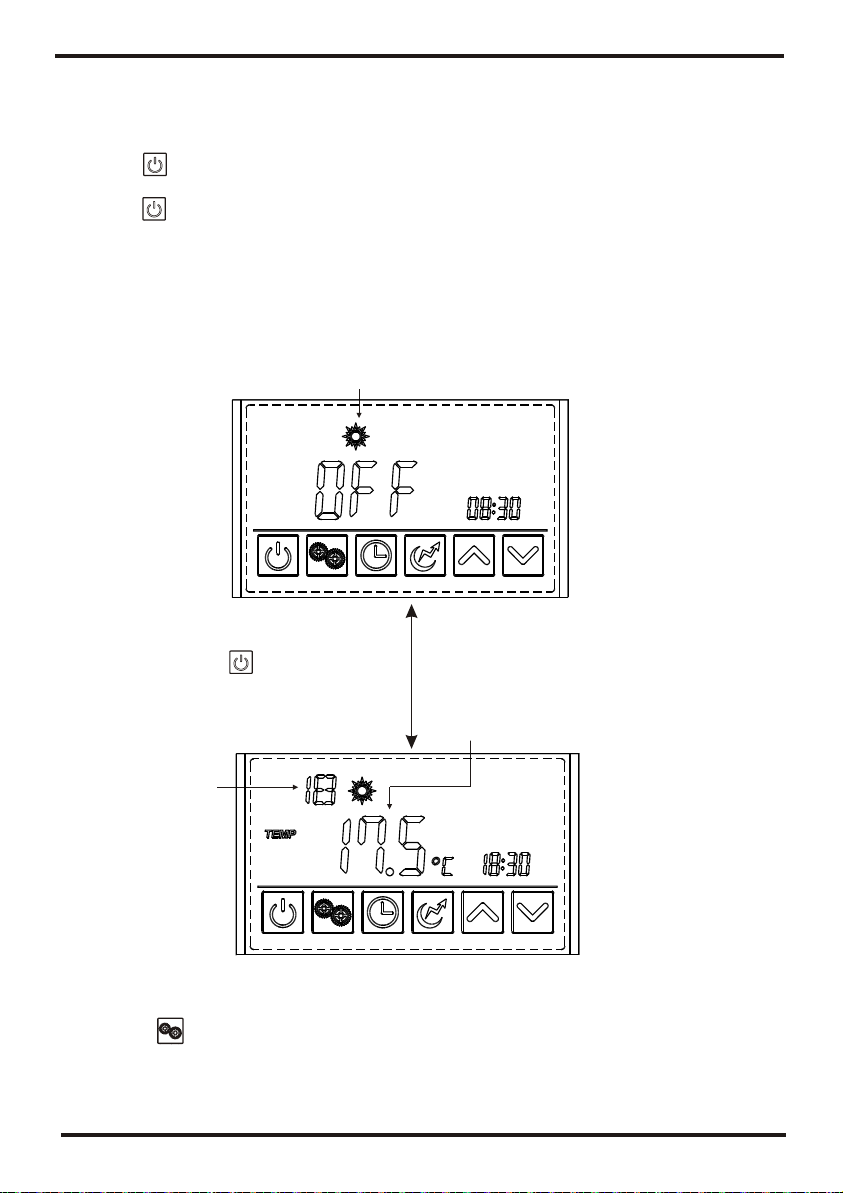
5.2.2 Modeselection
Press " " to select themode from Heating,Eco.heating , , Vacation, High
requirement in thestandby or runninginterface.
For example:
Intelligent
Running interface
5.2.1 TurnON/OFF the unit
Press " " and hold for0.5s in thestandby interface ofthe wire controllerto turn onthe
unit and atthis time themain display areashows the wateroutlet temperature.
Press " "and hold for 0.5s in therunning interface ofthe wire controllerto turn off the
unit and atthis time themain display areashows OFF.
Note: TheON/OFF button canonly be usedto turn on/off the unitin standby orrunning
interface of thewire controller.
5.2.3 Target temperature checkingand setting
In the standbyor running interface,press " "or " "once to checkthe target temperature
of the outletwater. Press " " or " " againto change thetarget temperature.After making
the changes tothe parameter,press " "to confirm or" " tocancel the changes,then
return to theprevious interface. Ifno operations areperformed on thekeypad for 5s,the
controller exits theparameter modification menuby timeout andthe changes areconfirmed.
Setting 75 " "
" "
C When the targettemperature is adjustedto 60 C, press andhold the for
5s. Atthis time, thetarget temperature isdisplayed as 61 C and thetemperature range
changed to 38-75C. Press the to set thetarget temperature to75 C.
Example: Change thetarget temperature from55 C to 70C when the actualoutlet water
temper is 18.
Press
Press
Press
Heating mode
Outlet water
temperature
Time Eco.heating mode
Vacation mode
Date
modeIntelligent
Press High requirement mode

15
5.Usage
16
5.Usage
5.2 Usageof wirecontroller
Outlet water temperature
Press " " and hold for0.5s.
Inlet water
temperature
Heating mode
Standby interface
5.2.2 Modeselection
Press " " to select themode from Heating,Eco.heating , , Vacation, High
requirement in thestandby or runninginterface.
For example:
Intelligent
Running interface
5.2.1 TurnON/OFF the unit
Press " " and hold for0.5s in thestandby interface ofthe wire controllerto turn onthe
unit and atthis time themain display areashows the wateroutlet temperature.
Press " "and hold for 0.5s in therunning interface ofthe wire controllerto turn off the
unit and atthis time themain display areashows OFF.
Note: TheON/OFF button canonly be usedto turn on/off the unitin standby orrunning
interface of thewire controller.
5.2.3 Target temperature checkingand setting
In the standbyor running interface,press " "or " "once to checkthe target temperature
of the outletwater. Press " " or " " againto change thetarget temperature.After making
the changes tothe parameter,press " "to confirm or" " tocancel the changes,then
return to theprevious interface. Ifno operations areperformed on thekeypad for 5s,the
controller exits theparameter modification menuby timeout andthe changes areconfirmed.
Setting 75 " "
" "
C When the targettemperature is adjustedto 60 C, press andhold the for
5s. Atthis time, thetarget temperature isdisplayed as 61 C and thetemperature range
changed to 38-75C. Press the to set thetarget temperature to75 C.
Example: Change thetarget temperature from55 C to 70C when the actualoutlet water
temper is 18.
Press
Press
Press
Heating mode
Outlet water
temperature
Time Eco.heating mode
Vacation mode
Date
modeIntelligent
Press High requirement mode

5.Usage
17
Outlet water temperature
Time Target temperature
Press and hold the for 5s ,then press
or again to change the target
temperature.
Press
to confirm
or to
cancel, then
return to the
previous
interface.
Press
to change the
target
temperature
from 55 to
60 .
5.2.4 Timesetting
In the standbyor running interface, do as followsto set thetime when inheating mode. When
press " "once, the timeparameter will flash.When press " " again, thehour parameter
will flash thenpress " "or " "to change it.After makingthe changes tothe parameter,
press" " toconfirm, then changethe minute parameteras well asthe date parameterin the
same way.
If no operationsare performed onthe keypad for10s, the controllerexits the parameter
modification menu bytimeout and thechanges are confirmed.
Note: Set the datein the sameway when in vacation mode.
Example: Change thetime and datefrom 18:30 onAugust 4thto 17:40 onSeptember 8th.
Time
Press
twice then
press or
to change
the hour
parameter
and press
to confirm.
Press " " or " " to change the minute
parameter.
5. Usage
18
The new set time
Press " " to confirm.
Press " " or " " to change the minute
parameter.
The date is flashing
Press once then press or to change
the month parameter and press to confirm.
Press " " or
" " to change
the day parameter.
Press" "
to confirm.
5.2.5 Timersetting
5.2.5.1 Under thestandard mode, economicmode, intelligent mode,you can enterthe timer
setting.
Press " "and hold for2s, the "ON"and " 1 " will flash,and then youcan set theturn on
time of timer1as the 24clock setting show. Afterfinishing, " OFF" and " 1 " willflash, that
means you canset the turnoff timeof timer1.The "ON "and " 2 " will flashafter finishing the
timer1 setting, youcan set theturn on timeof timer2.After finishing, the" OFF "and " 2" will
flash, and thenyou can setthe turn off time oftimer2. Press " " again tosave and backto
the interface. Ifyou don't needto set thetimer2, you canpress the " " to saveafter finishing
the timer1 setting.Youwill find the" ON "and " 2 " flash. Nooperation for 5s,the program will
back to theinterface automatically.
Note: When press" " andhold for 2s,the " ON " and "1 " willflash. It isnot necessary for
you to setthe turn ontime of thetimer1. You can sequentiallyto press " " for 2sto enter to
the turn off time oftimer1. So doesthe timer2. Orpress " "or " " to circularly display.
Timer Cancel:Press " " and hold for2s to enterinto the interface,and then press" "
to cancel allthe operation. Pleasesee the followingpicture for moredetails.
Table of contents
Other Solahart Heat Pump manuals


Popular Heat Pump manuals by other brands

alphainnoTec
alphainnoTec LW 161H-A/V operating manual

Glowworm
Glowworm Envirosorb 8 Instructions for use

alphainnoTec
alphainnoTec PWZS H1 Series operating manual

Aqua PRO
Aqua PRO ECO550 Installation and user manual

Pro-Team
Pro-Team P5 Installation and instruction manual

Seabreeze
Seabreeze SMZC9H4ZIGX user manual

Mark
Mark HKEU 353 Technical manual

Water Furnace
Water Furnace E Series installation manual

Trane
Trane Precedent PKGP-PRC003-EN user manual

Dimplex
Dimplex LA 17PS Installation and operating instructions

Dimplex
Dimplex WIH 120TU Installation and operating instruction

Galletti
Galletti EXCELIA MXE 009M manual


