Page 9 of 15
4.4 FUNCTION Select Buttons
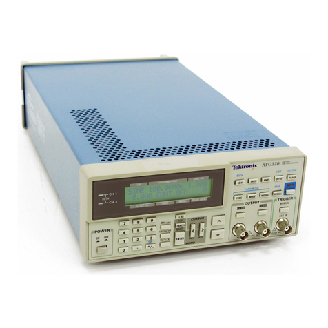
The FUNCTION select buttons are a horizontal set of white buttons on the lower right side of the
front panel. These buttons enable the operator to select from four functions. When a function is
active, the green LED in the top left corner of the button is illuminated. The default function
selected at power up is SINGLE PULSE ENABLE. In the group of four white function buttons, it
is the white button farthest to the left. When SINGLE PULSE ENABLE is selected, the generator
is able to produce single transients when the red SINGLE PULSE button is pressed; it is to the
left of the white SINGLE PULSE ENABLE button. The white PPS button selects the variable
repetition rate function. The last two white FUNCTION buttons select pulse positioning on 50/60
Hz and 400 Hz AC power signals, respectively.
IMAGE 2 –FUNCTION SELECT BUTTONS
4.5 Single Pulse Operation
Enables the user to discharge the 7054-2B’s output pulse manually by depressing the SINGLE
PULSE red button to the left of the SINGLE PULSE ENABLE function button.
4.6 PPS (Auto Repetition Rate)
The calibration of the knob in PPS is reasonably accurate (approximately ±10%) at all panel
markings. For applications where the exact rate is important, it may be measured on the time
base scale of the associated oscilloscope. The rate is independent of load conditions.
4.7 50/60 and 400 Hz Line SYNCs (Pulse Positioning)
With the equipment connected for series injection on AC lines, as shown in Diagram 2, select
either the 50/60 Hz or 400 Hz SYNC buttons as required. The power cord of the Model 7054-
2B must be connected to the same power source as the test sample.
However, when operating on a 400 Hz power line for the pulse position test, it is necessary to
connect the blower fan to the standard 50/60 Hz line. See Diagram 4. This is accomplished by
removing the parallel blade connector, P1, from its socket (adjacent to the fuses on the rear
panel) and connecting it to a primary AC line voltage source equivalent the 7054-2B’s normal
power source.
Connect the oscilloscope across the power input to the test sample. Avoid grounding the hot side
of the line through the case of the oscilloscope. A power line isolation transformer such as Solar
Type 7032-1 for 115 V or 7032-2 for 230 V is suggested at the power input to the scope, as
shown in Diagrams 2 and 4.


