Solar Electronics 7054-1 User manual

INTRUCTION MANUAL
FOR
MODEL 7054-1
SPIKE GENERATOR
March 10, 1971
Revised: June 11, 1976
Revised: March 9, 2007
Revised: June 30, 2009
Solar Electronics Company
A Division of A. T. Parker, Inc.
10866 Chandler Boulevard
North Hollywood, California 91601
Telephone: (818) 755-1700 Fax: (818) 755-0078

Solar Electronics Company
2 of 22
4
4
6
7
7
7
8
9
9
10
10
10
11
11
11
11
11
13
15
15
16
16
17
17
18
TABLE OF CONTENTS
1.0 Application…………………………………………………………………………...
2.0 Description…………………………………………………………………………..
3.0 Specifications……………………………………………………………………….
4.0 Operation………………………………………………………………………….....
4.1 General…………………………………………………………………........
4.2 Interconnections for Parallel Injection…………………………...........
4.3 Interconnections for Series Injection………………………….............
4.4 FUNCTION Switch…………………………........…………………………
4.5 Pulse Positioning…………………………........………………………….
4.6 Repetition Rate…………………………........………………………….....
4.7 Spike Amplitude…………………………........…………………………...
4.8 Amplitude with Low Impedance Loads…………………………..........
4.9 Pulse Shape…………………………........…………………………..........
5.0 Maintenance and Calibration…………………………......................................
5.1 Equipment
Required…………………………........................................+
5.2 Preliminary Procedure.........................................................................
5.3 Voltage Check......................................................................................
5.4 Trigger Waveform................................................................................
5.5 Check and Adjustment of Maximum Amplitude................................
5.6 Check and Adjustment of Frequency Calibration.............................
5.7 Check and Adjustment of Range of Pulse.........................................
5.8 Check and Adjustment of Range of Pulse.........................................
5.9 Check of Single Pulse Function.........................................................
5.10 Compare Waveforms on 2K Ω50 W Resistors................................
6.0 Parts List…………………………........................................……………………..

Solar Electronics Company
3 of 22
4
5
13
14
7
8
8
9
12
12
17
Oscilloscope Plots, Illustrations and Images
Oscilloscope Plots
Figure 1 – Pulse Shape with 5 ΩLoad on Either Series or Parallel Output…………...
Figure 2 – Pulse Shape with 0.5 ΩLoad on Either Series or Parallel Output…………
Figure 9 – Waveform at output of Q5, Amplitude at zero…………………………………
Figure 10 – Waveform at output of Q5, Amplitude at maximum………………………...
Illustrations
Figure 3 – Parallel Injection on DC Line……………………………………………………..
Figure 4 – Series Injection on AC Line……………………………………………………….
Figure 5 – Series Injection on DC Line, Measuring 7054-1 Spike Only………………...
Figure 6 – Setup for Pulse Position Test on 400 Hz Line…………………………………
Images
Figure 7 – Printed Circuit Board Reference Designators…………………………………
Figure 8 – Adjustment Sliders and Measurement Point…………………………………..
Figure 11 – 2K Ω50 W Resistors……………………………………………………………...
Solar Electronics Company
4 of 22
1.0 Application
The model 7054-1 Spike Generator was specifically designed for screen room use in
making conducted transient susceptibility tests as required by MIL-STD-826A, MIL-STD-
461A/462 and other RFI/EMI specifications.
2.0 Description
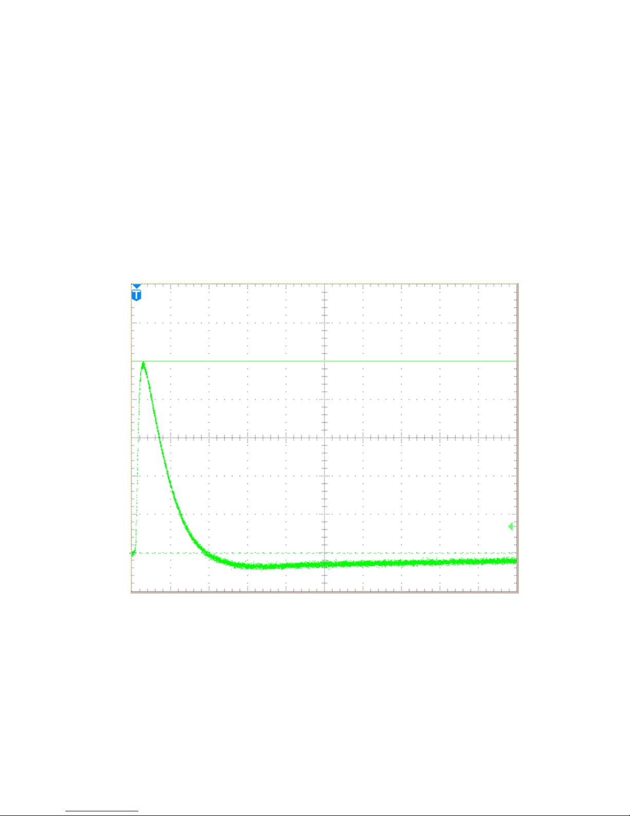
The model 7054-1 Spike Generator provides a transient pulse (spike) with amplitude
adjustable up to 600 V peak. Using parallel injection into a resistive load, the output
transient closely follows an idealized curve with less than 1 µs rise time and falling to
10% of full voltage in approximately 10 µs. See Figure 1 and 2. The repetition rate is
adjustable from 0.8 pulses per second (pps) to 10 pps.
10 20 30 40 50 60 70 80 90
Vertical: 20 V/div
Horizontal: 10 µs/div
Frequency: 10 pps
Amplitude: 100 V peak into 5 Ωload
Figure 1 – Pulse shape with 5 Ωload on either series or parallel output
120
0
20
40
60
80
100
Am
p
litude, Volts
Microseconds
Solar Electronics Company
5 of 22
2 4 6 8 10 12 14 16 18
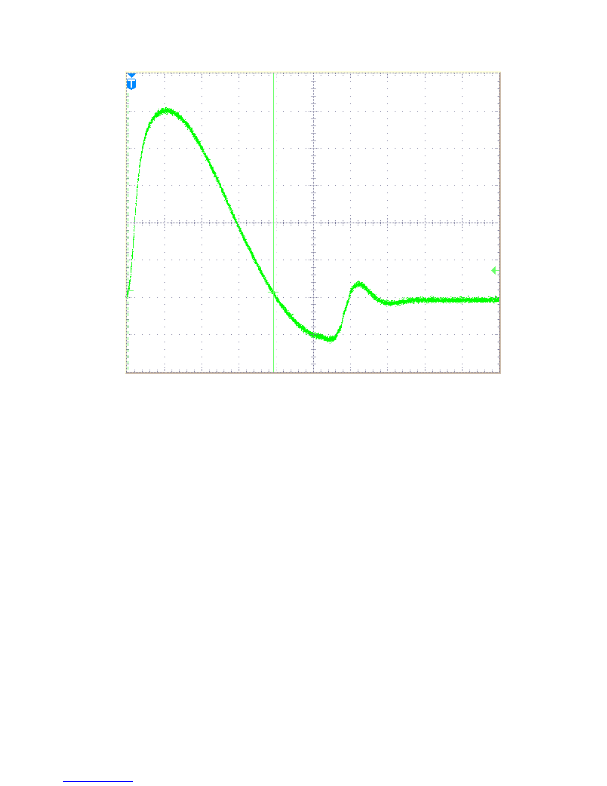
Vertical: 20 V/div
Horizontal: 2 µs/div
Frequency: 10 pps
Amplitude: 100 V peak into 0.5 Ωload
Figure 2 – Pulse shape with 0.5 Ωload on either series or parallel output
A FUNCTION switch allows either recurring spikes at a selected rate or provides for
single spikes by a panel-mounted push button. The FUNCTION switch also provides for
synchronization with 60 Hz* or 400Hz lines.
When synchronizing with AC lines, the PULSE POSITION knob allows for phase
adjustment of the spike to position it anywhere on the AC sine wave.
The PARALLEL output terminals provide for injection of the spike in parallel with the
load. The SERIES output terminals provide connections for series injection. The output
terminals are isolated from the chassis and the AC line.
100
-20
0
20
40
60
80
Am
p
litude, Volts
Microseconds

Solar Electronics Company
6 of 22
3.0 Specifications
Spike Repetition Rate
Continuously adjustable from 0.8 pps to 10 pps
Spike Amplitude
Continuously adjustable from 5 V to 600 V peak
Spike Duration
Output falls to 10% of full voltage in approximately 10 µs with a 5 Ωload on the
SERIES output terminals
Rise Time
Less than 1 µs into 5 Ωresistive load
Spike Shape
Ringing characteristic as per Figure 1 and Figure 2
Phase Adjustment
Adjustable from 0° to 360° on 60 Hz* or 400 Hz lines
Internal Impedance
Approximately 0.5 Ω
Power Line Current in Series Injection Mode
Handles 25 A RMS at power frequencies or DC
Power Requirement
115 V 60-400 Hz, 1.6 A**
Size
19” rack panel, 7” high x 12-3/4” deep, less projections
Weight
US: 36 lb.; Metric: 16.3 kg.
Solar Electronics Company
7 of 22
4.0 Operation
4.1 General
Parallel Injection is most often used for DC lines. Series injection is always used on AC
lines. CAUTION! DO NOT CONNECT OUTPUT OF SPIKE GENERATOR IN
PARALLEL WITH AC LINES. ALTHOUGH SERIES INJECTION CAN BE USED ON
EITHER AC OR DC LINES, PARALLEL INJECTION MUST NOT BE USED ON AC
LINES SINCE SEVERE DAMAGE TO THE SPIKE GENERATOR WILL RESULT.
4.2 Interconnections for Parallel Injection
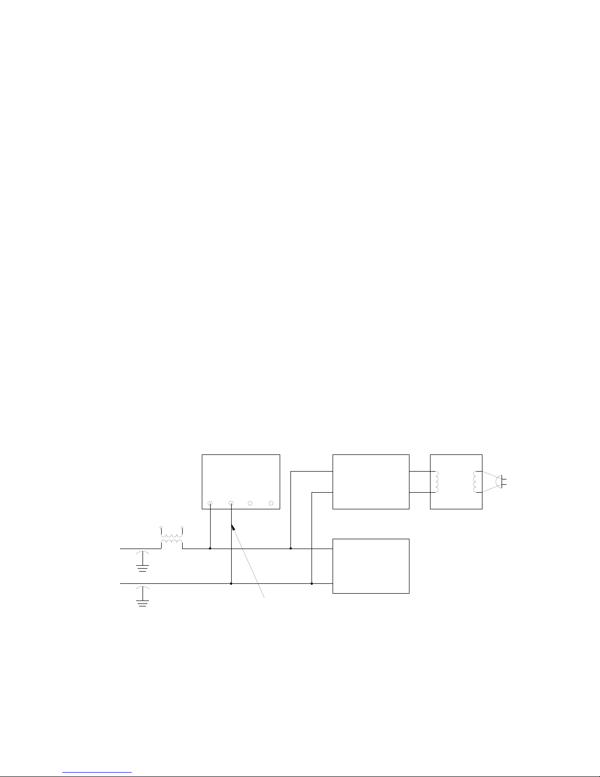
As shown in Figure 3, connect the oscilloscope to the terminals marked PARALLEL.
Also connect these terminals to the DC input power leads of the equipment under test.
Take precautions to prevent grounding the load through the case of the oscilloscope.
Use a Solar type 7032-1 Isolation Transformer or equivalent at the power input to the
oscilloscope. All output terminals on the Spike Generator are isolated from the case of
the unit.
When parallel injecting the spike into a DC line, it is desirable to use an inductor in series
with the power source so that the spike is applied to the test sample without the R.F.
shunting effect of the power source impedance. The secondary of Solar Type 6220-1A
Audio Isolation Transformer is well suited for this application and is capable of carrying
50 A of test sample current.
Solar
7054-1
Oscilloscope
Solar
7032-1
Isolation
Transformer
Test Sample
A.C.
D.C. Line
Solar
6512-106R
10 µF
Solar
6220-1A
FIGURE 3 - PARALLEL INJECTION ON D.C. LINE
Parallel
Output
Parallel Series
Solar Electronics Company
8 of 22
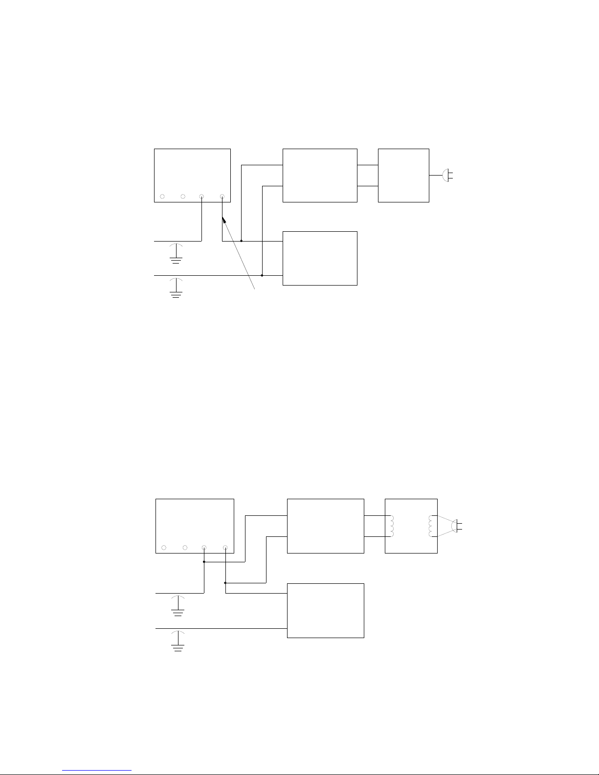
4.3 Interconnections for Series Injection
For series injection, connect the output terminals marked SERIES in series between the
power source and the test sample as shown in Figure 4. It is recommended that the
injection be in series with the ungrounded side of the power line.
Solar
7054-1
Oscilloscope
Solar
7032-1
Isolation
Transformer
Test Sample
A.C.
A.C. Line
Solar
6512-106R
10 µF
Series
Output
FIGURE 4 - SERIERS INJECTION ON A.C. LINE
Parallel Series
The series connection is capable of handling 25 A RMS or DC This connection inserts
approximately 75 µH in series with the test sample. The power frequency voltage drop
across this reactance is 4.75 V at 25 A, 400 Hz.
The oscilloscope should be connected across the SERIES output terminals to indicate
the shape and magnitude of the spike being injected into the circuit. See Figure 5.
However, the spike as it appears on the AC waveform into the test sample is best seen
by connecting the oscilloscope across the power input leads to the test sample, as
shown in Figure 4. Precautions must be taken to avoid grounding the hot side of the
power line through the case of the oscilloscope.
Solar
7054-1
Oscilloscope
Solar
7032-1
Isolation
Transformer
Test Sample
A.C.
D.C. Line
Solar
6512-106R
10 µF FIGURE 5 - SERIES INJECTION ON D.C. LINE
OSCILLOSCOPE MEASURING 7054-1 SPIKE ONLY
Parallel Series

Solar Electronics Company
9 of 22
4.4 FUNCTION Switch
This control enables the operator to select from three functions. In the extreme left,
SINGLE PULSE position, it provides for pushbutton operation of single transients. The
FREQUENCY P.P.S. position selects the variable repetition rate function. The last two
FUNCTION switch positions select pulse positioning on 60Hz and 400Hz AC power
signals respectively.
4.5 Pulse Positioning
With the equipment connected for series injection on AC lines, as shown in Figure 4,
place the FUNCTION switch in 60 Hz* or 400 Hz SYNC position as required. The power
cord of the Spike Generator must be connected to the same power source as the test
sample.
However, when operating on a 400 Hz power line for the pulse position test, it is
necessary to connect the blower fan to the standard 60 Hz* line. See figure 6. This is
accomplished by removing the parallel blade connector, P1, from its socket (adjacent to
the fuses on the rear panel) and connecting it to a primary power source of 115 V 60
Hz*.
Connect the oscilloscope across the power input to the test sample. Avoid grounding the
hot side of the line through the case of the oscilloscope. A power line isolation
transformer such as Solar type 7032-1 is suggested at the power input to the scope, as
shown in figures 4 and 6.
Oscilloscope Sola
r
7032-1
Test Sample
400
Hz
Line
Sola
r
6512-106R
10 µF
Series
Output
FIGURE 6 - SETUP FOR PULSE POSITION TEST ON 400 Hz LINE
115 V
400 Hz
Line
P1
Sola
r
7054-1
Parallel Series
115 V
60 Hz
LINE

Solar Electronics Company
10 of 22
The PULSE POSITION control in conjunction with the polarity reversing switch will
enable phase shift of the injected spike through 360° as observed on the oscilloscope.
The phase reversing switch at the bottom of the panel will allow adjustment of the spike
position to the positive half cycle or the negative half cycle of the power line sine wave.
Due to the phase difference existing, the knob position corresponding to the voltage zero
crossover will differ from one test sample to another.
When synchronizing on a 60 Hz* line, the spike appears on every 8th sine wave of the
power frequency. On a 400 Hz line, the spike appears on every 64th sine wave. The
spike position, however, is the same on each sine wave on which the spike appears.
This periodic injection of the spike is due to the 7.5** pps rate on 60 Hz* lines and a rate
of 6.2 pps on 400 Hz lines. (In this equipment, the repetition rate must be kept below
10 pps to allow time for the charging of the capacitors which provide the energy for the
spike.)
CAUTION: WHEN OPERATING ON A 400 HZ POWER LINE, DO NOT LEAVE THE
FUNCTION SWITCH IN THE 60 HZ POSITION FOR PROLONGED PERIODS SINCE
IT MAY CAUSE OVERHEATING OF THE POWER SUPPLY.
Upon completion of the 400 Hz pulse positioning test, reinsert the parallel blade
connector into the mating socket. This connector should remain in this position for all
other uses of the Spike Generator.
4.6 Repetition Rate
The calibration of the knob in pps is reasonably accurate (approximately ±10%) at all
panel markings. For applications where the exact rate is important, it may be measured
on the time base scale of the associated oscilloscope. The rate is independent of load
conditions.
4.7 Spike Amplitude
The amplitude of the spike is adjustable from approximately 5 V to 600 V peak by means
of the AMPLITUDE knob. The calibration of this scale is most accurate at 100 V with a
resistive load greater than 5 Ωand with a repetition rate of 10 pps. For adjustment of
amplitude into unknown loads, the knob must be adjusted while watching the spike
amplitude on an oscilloscope with calibrated vertical amplitude.
4.8 Amplitude with Low Impedance Loads
Since the internal impedance of the Spike Generator is of the order of 0.25-1.0 Ω, the
amplitude into a matched load will be one half that of the open circuit amplitude. This
characteristic enables the operator to estimate the load impedance when it is
approaching the internal impedance of the generator.

Solar Electronics Company
11 of 22
4.9 Pulse Shape
When unloaded or connected to a purely resistive load, the spike shape is approximately
that of Figure 1. For low impedance or reactive loads, the shape is modified in terms of
load. Figure 2 indicates the spike shape when connected to a 0.5 Ωresistive load.
5.0 Maintenance and Calibration
Periodically make the following tests to verify the performance of the Spike Generator.
Make any adjustments required to bring the performance within the specified limits.
5.1 Equipment Required
The following equipment is required for the tests and adjustments described below:
1. Variac, 105-135 V, 60 to 400 Hz,* capable of handling 2 A
2. AC voltmeter, range suitable for measuring line voltage at 60 ** and 400
Hz
3. Calibrated oscilloscope
4. DC voltmeter
5. Single phase 400 Hz power source, capable of supplying 2 A
6. 5 Ωresistor, ±10%, ≥20 W
7. 6 V, 400 Hz transformer
5.2 Preliminary Procedure
Be sure the line cord of the Spike Generator is disconnected from the primary source.
Remove screws in top cover and in bottom cover.
Connect the variac to a 115 V 60 Hz* power source. Plug the Spike Generator into
output of variac. Connect the voltmeter across the variac output and maintain 115 V***
input to Spike Generator throughout the test.
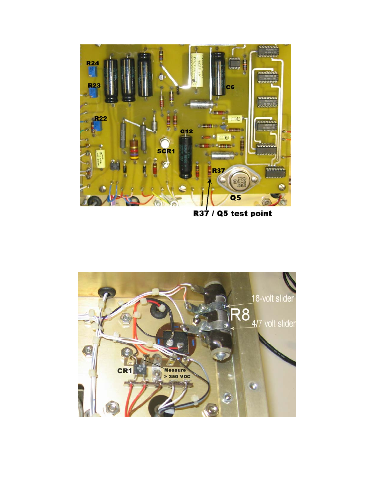
5.3 Voltage Check
DC voltage across the 500 µF capacitor C6, should be 4 V ±10% for older 7054-1's or 7
V ±10% for more recent 7054-1's. Voltage across the 500 µF capacitor C12 should be
18 V DC ±10%. See Figure 7. If necessary, adjust the sliders on R8 shown in Figure 8
to obtain these voltages.
Solar Electronics Company
12 of 22
FIGURE 7- PRINTED CIRCUIT BOARD REFERENCE DESIGNATORS
The DC voltage out of rectifier CR1 should be at least 350 V for rightmost rotation of the
knob. See Figure 8 for CR1 measurement point.
FIGURE 8- ADJUSTMENT SLIDERS AND MEASUREMENT POINT

Solar Electronics Company
13 of 22
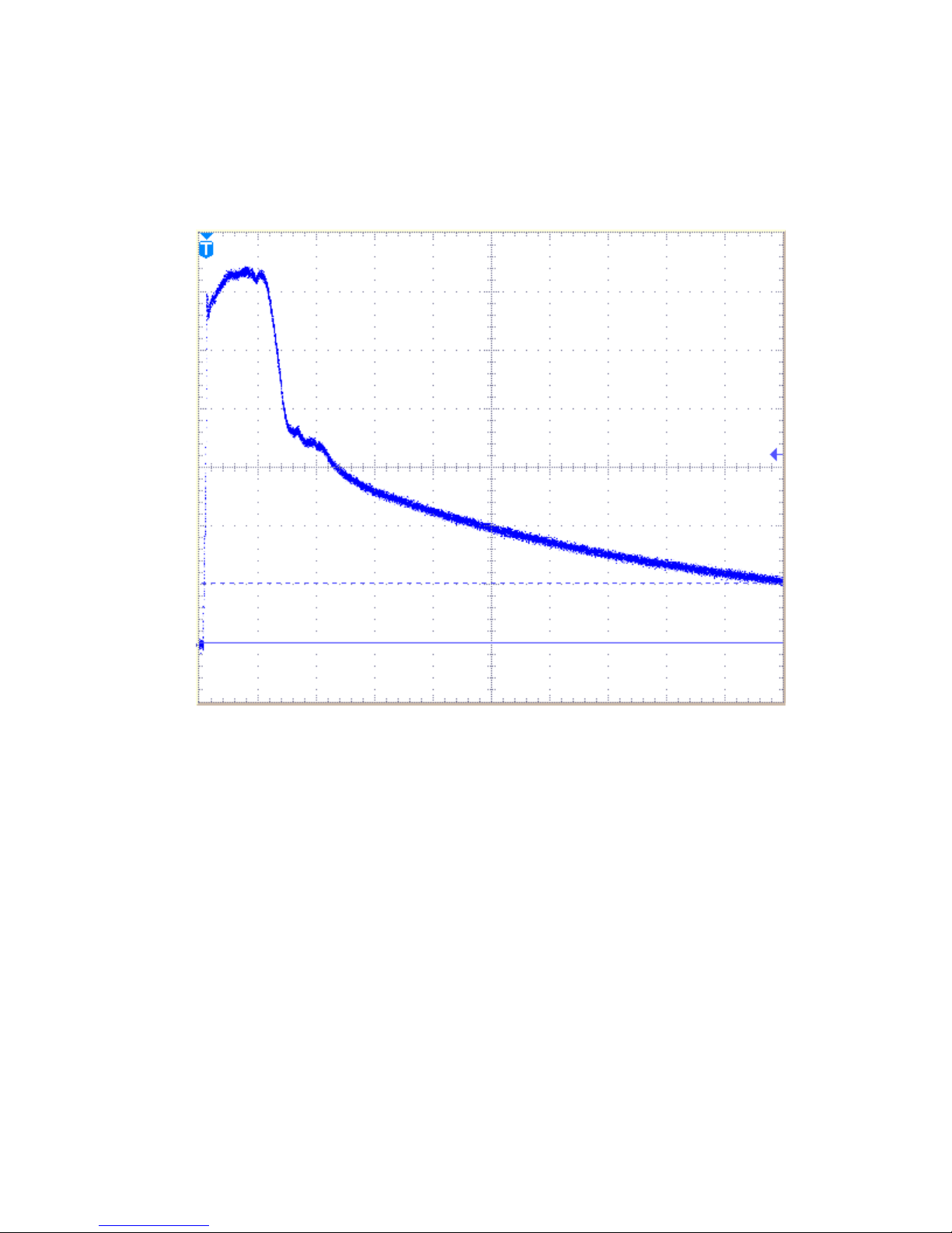
5.4 Trigger Waveform
Connect the oscilloscope across R37 at the output of Q5 in Figure 7. The common lead
of the oscilloscope may be left on the negative end of C6 or C12. With the FUNCTION
switch at FREQUENCY P.P.S., the frequency at 10 pps, the AMPLITUDE knob at zero,
the waveform should be similar to that of Figure 9.
20 40 60 80 100 120 140 160 180
Vertical: 2 V/div
Horizontal: 20 µs/div
FIGURE 9 – Waveform at output of Q5, Amplitude at zero
With the AMPLITUDE knob adjusted for maximum output, the waveform of Figure 9 will
be modified due to kickback from the SCR firing and will resemble that of Figure 10.
10
-2
0
2
4
6
8
Am
p
litude, Volts
Microseconds
Solar Electronics Company
14 of 22
20 40 60 80 100 120 140 160 180
Vertical: 2 V/div
Horizontal: 20 µs/div
FIGURE 10 – Waveform at output of Q5, Amplitude at maximum
10
-2
0
2
4
6
8
Am
p
litude, Volts
Microseconds

Solar Electronics Company
15 of 22
5.5 Check and Adjustment of Maximum Amplitude
To check and, if required, adjust the maximum amplitude, proceed as follows:
Connect the 5 Ωresistor across the SERIES output terminals on the Spike Generator.
Connect oscilloscope input to SERIES output terminals on the Spike Generator.
Adjust oscilloscope controls to display 600 V peak at 10 pps.
Turn Spike Generator on.
Set FUNCTION switch to the FREQUENCY P.P.S. position.
Set FREQUENCY P.P.S. knob to 10.
Rotate AMPLITUDE control to the leftmost position.
Oscilloscope should display peak amplitude of at least 600 V.
On the oscilloscope, verify that the pulse reaches peak amplitude in less than 1 µs and
decays to zero in 8-14 µs.
Adjust AMPLITUDE control until oscilloscope displays 100 V peak.
Verify that AMPLITUDE knob indicates 100. If it does not, loosen set screws and move
knob on shaft to indicate 100 when oscilloscope displays peak amplitude of 100 V.
NOTE: All other tests and adjustments will be made at 100 V amplitude.
5.6 Check and Adjustment of Frequency Calibration
To check and adjust the frequency calibration, proceed as follows:
Place the 5 Ω20 W or greater resistor on the SERIES output terminals and connect the
oscilloscope across it.
Set FUNCTION switch to FREQUENCY P.P.S. and the rate to 10.
Set oscilloscope sweep for 20 ms/div and set vertical amplifier to 5V/div.
There should be a pulse on every 5th division on the oscilloscope grid and a total of 3
pulses.
If necessary, adjust 5K potentiometer, R22, in Figure 7, until a pulse appears at each
major division on the oscilloscope, with a total of 10 pulses. With the oscilloscope sweep
adjusted for 0.1 sec/div, this display corresponds to a frequency of 10 pps.

Solar Electronics Company
16 of 22
5.7 Check and Adjustment of Range of Pulse Position Control at 60 Hz
To check and adjust the range of the PULSE POSITION control at 60 Hz*, proceed as
follows:
Set FUNCTION switch on Spike Generator to 60~SYNC.
Set oscilloscope sweep for 1 ms/div, automatic sweep triggered to the positive (+) half of
the line cycle.
Rotate PULSE POSITION control on Spike Generator. One pulse should appear on
oscilloscope. If more than one pulse appears, replace SCR1 in Figure Sissy
When the PULSE POSITION control is rotated over its full range, the pulse should move
8 ½ ** divisions on the oscilloscope grid. If necessary, adjust potentiometer R23, in
Figure Sissy, until the PULSE POSITION control moves the pulse 8 ½** oscilloscope
divisions over its full range.
5.8 Check and Adjustment of Range of Pulse Position Control at 400 Hz
To check and adjust the range of the PULSE POSITION control at 400 Hz, proceed as
follows:
Connect a variac to 115 V*** 400Hz power source. Maintain 115 V *** output from the
variac throughout the following tests.
Connect a 6 V, 400 Hz transformer to the external trigger input to the oscilloscope. The
transformer must use the same power source as the Spike Generator.
Turn on the Spike Generator and set the FUNCTION switch to 400~SYNC, and the sync
phase switch (marked + and -) to +.
Set the oscilloscope sweep for 0.2 ms/div, automatic sweep, external trigger. The
oscilloscope should display a single pulse.
Rotate PULSE POSITION control clockwise and counterclockwise so pulse travels
across the display.
The pulse should travel 6¼ divisions.
If necessary, adjust R24, in Figure Sissy, until the pulse travels 6¼ divisions.

Solar Electronics Company
17 of 22
5.9 Check of Single Pulse Function
To check generation of a single pulse, proceed as follows:
Set the FUNCTION switch to the leftmost position to SINGLE PULSE.
Press the pushbutton switch several times. Observe that each time the switch is
depressed a pulse appears on the oscilloscope.
When this test is completed, return the Spike Generator to operation from a 60 Hz*
primary source.
5.10 Compare Trigger Waveforms
See Figure 11. Prepare the oscilloscope to measure around 300 volts. Connect a scope
probe ground lead to the 7054-1 chassis. Turn the 7054-1 on. Set the AMPLITUDE
knob to maximum. Set the FUNCTION knob to FREQUENCY P.P.S.. Set the repetition
rate knob to 10 pps. Being careful not to touch any component leads with your hand,
probe the top terminal of each of the eight indicated 2K Ω50 W resistors to verify that
the waveforms are about the same on each resistor.
FIGURE 11- 2K Ω50 W RESISTORS

Solar Electronics Company
18 of 22
6.0 Parts List
Reference
Designator Description
B1 Filter Muffin Fan, Rotron
C1 Capacitor, 0.1 µF 400 V GMV, Mylar Foil, 250B
C2 Capacitor, 500 µF 50 V DC, Electrolytic
C3 Capacitor, 80 µF 450 V DC, Sprague TVL-1735
C4 Capacitor, 500 µF 50 V DC, Electrolytic
C5 Capacitor, 270 pF, DM, Mica
C6 Capacitor, 500 µF 50 V DC, Electrolytic
C7 Capacitor, .33 µF 200 V 5%, Metalized Mylar, 210B
C8 Capacitor, 500 µF 50 V DC, Electrolytic
C9 Capacitor, .22 µF 200 V 5%, Metalized Mylar, 210B
C10 Capacitor, .15 µF 200 V 5%, Metalized Mylar, 210B
C11 Capacitor, .033 µF 200 V 5%, Metalized Mylar, 210B
C12 Capacitor, 500 µF 50 V DC, Electrolytic
C13 Capacitor, 1 µF 200 V 10%, Metalized Mylar, 210B
C14 Capacitor, 50 µF 25 V, Sprague TE-1209
C15 Capacitor, 1 µF 200 V 10%, Metalized Mylar, 210B
C16 Capacitor, .01 µF 150 V, Disc
C17 Capacitor, 50 µF 25 V, Sprague TE-1209
C18 Capacitor, .33 µF 100 V GMV, Metalized Mylar, 210B
C19 Capacitor, .33 µF 100 V GMV, Metalized Mylar, 210B
C20 Capacitor, 2 µF 600 V, Cornell-Dubilier DYR-6200
C21 Capacitor, 2 µF 600 V, Cornell-Dubilier DYR-6200
C22 Capacitor, .22 µF 400 V, GMV, Mylar Foil, 250B
C23 Capacitor, 2 µF 600 V, Cornell-Dubilier DYR-6200
C24 Capacitor, 2 µF 600 V, Cornell-Dubilier DYR-6200
C25 Capacitor, .22 µF 400 V, GMV, Mylar Foil, 250B
C26 Capacitor, .33 µF 100 V GMV, Metalized Mylar, 210B
C27 Capacitor, .33 µF 100 V GMV, Metalized Mylar, 210B
C28 Capacitor, 2 µF 600 V, Cornell-Dubilier DYR-6200
C29 Capacitor, 2 µF 600 V, Cornell-Dubilier DYR-6200
C30 Capacitor, .22 µF 400 V, GMV, Mylar Foil, 250B
C31 Capacitor, 2 µF 600 V, Cornell-Dubilier DYR-6200
C32 Capacitor, 2 µF 600 V, Cornell-Dubilier DYR-6200
C33 Capacitor, .22 µF 400 V, GMV, Mylar Foil, 250B
C34 Capacitor, .33 µF 100 V GMV, Metalized Mylar, 210B
C35 Capacitor, .33 µF 100 V GMV, Metalized Mylar, 210B
C36 Capacitor, 2 µF 600 V, Cornell-Dubilier DYR-6200
C37 Capacitor, 2 µF 600 V, Cornell-Dubilier DYR-6200

Solar Electronics Company
19 of 22
C38 Capacitor, .22 µF 400 V, GMV, Mylar Foil, 250B
C39 Capacitor, 2 µF 600 V, Cornell-Dubilier DYR-6200
C40 Capacitor, 2 µF 600 V, Cornell-Dubilier DYR-6200
C41 Capacitor, .22 µF 400 V, GMV, Mylar Foil, 250B
C42 Capacitor, .33 µF 100 V GMV, Metalized Mylar, 210B
C43 Capacitor, .33 µF 100 V GMV, Metalized Mylar, 210B
C44 Capacitor, 2 µF 600 V, Cornell-Dubilier DYR-6200
C45 Capacitor, 2 µF 600 V, Cornell-Dubilier DYR-6200
C46 Capacitor, .22 µF 400 V, GMV, Mylar Foil, 250B
C47 Capacitor, 2 µF 600 V, Cornell-Dubilier DYR-6200
C48 Capacitor, 2 µF 600 V, Cornell-Dubilier DYR-6200
C49 Capacitor, .22 µF 400 V, GMV, Mylar Foil, 250B
C50 Capacitor, 10 µF 1000 V, Cornell-Dubilier, T10100
C51 Capacitor, 10 µF 1000 V, Cornell-Dubilier, T10100
CR1 Diode Quad, Motorola MDA-920-7
CR2 Not Used
CR3 Diode, 1 A 200 V, Diodes DI-72
CR4 Diode, 1 A 200 V, Diodes DI-72
CR5 Diode Bridge, 1 A 100 V, Motorola MDA-920-3
DS1 Pilot Light, Eldema EG01-RCB-NE2E 100K
F1 Fuse, 115 V: 2 A
F2 Fuse, 115 V: 2 A
FL1 Line Filter, Solar
IC1 Integrated Circuit, Motorola MC-890P
IC2 Integrated Circuit, Motorola MC-890P
IC3 Integrated Circuit, Motorola MC-890P
IC4 Integrated Circuit, Motorola MC-890P
IC5 Integrated Circuit, Motorola MC-892P
J1 Jack, 2 wire AC
J2 Jack, Banana Type
J3 Jack, Banana Type

Solar Electronics Company
20 of 22
L1 Toroid, Solar 705408
L2 Toroid, Solar 705408
L3 Toroid, Solar 705408
L4 Toroid, Solar 705408
L5 Toroid, Solar 705408
L6 Toroid, Solar 705408
L7 Toroid, Solar 705408
L8 Toroid, Solar 705408
P1 Plug, 2 Wire AC
P2 Plug, 3 Wire AC
Q1 Transistor, Motorola 2N3904
Q2 Transistor, Motorola 2N3904
Q3 Unijunction Transistor, Motorola 2N2647
Q4 Transistor, Motorola 2N3905
Q5 Transistor, Motorola 2N3773
R1 Resistor, Part of DS1 (Add 150K 1/2 W for 230 V)
R2 Resistor, 100 Ω50 W WW, Ohmite
R3 Resistor, 2K Ω50 W WW, Ohmite
R4 Resistor, Dividohm, 1 K Ω50 W WW, Ohmite
R5 Resistor, 4 K Ω4 W WW, Ohmite
R6 Resistor, 4.7 K Ω1 W 10%, Ohmite
R7 Resistor, 1.2 K Ω5 W WW, Ohmite
R8 Resistor, 150 Ω25 W WW, Ohmite, Dividohm
R9 Resistor, 2.2 K Ω1/2 W 10%
R10 Resistor, 1.2 K Ω1/2 W 10%
R11 Resistor, 12 K Ω1/2 W 10%
R12 Resistor, 8.2 K Ω1/2 W 10%
R13 Resistor, 27 K Ω1/2 W 10%
R14 Resistor, 10 K Ω1/2 W 10%
R15 Resistor, 220 Ω1/2 W 10%
R16 Resistor, 3.3 K Ω1/2 W 10%
R17 Resistor, 1.2 K Ω1/2 W 10%
R18 Resistor, 1.2 K Ω1/2 W 10%
R19 Resistor, 1.2 K Ω1/2 W 10%
R20 Resistor, Variable 50 K Pot
R21 Resistor, Variable 50 K Pot
R22 Resistor, Variable 5 K Trimpot, Bourns 3067P
R23 Resistor, Variable 5 K Trimpot, Bourns 3067P
R24 Resistor, Variable 20 K Trimpot, Bourns 3067P
Table of contents
Other Solar Electronics Portable Generator manuals


