Solar Heat Exchange SHEM40-80SDB-XG Instruction Manual

SIMPLE DRAINBACK
DOMESTIC HOT WATER SOLAR SYSTEM
WITH DIFFERENTIAL CONTROL
TWO TANK CONFIGURATION
GAS BACK-UP
TWO TANK CONFIGURATION
ELECTRIC BACK-UP
SHEM40-80SDB-XG
SHEM64-80SDB-XG
80SDB-XG-Suntask 1
80SDB-XG-Suntask 2
80SDB-XG-TPP2-2
80SDB-XG-TPP2-3
80SDB-XG-TPP24-2
80SDB-XG-VHP30-1
80SDB-XG-VHP30-2
SHEM40-80SDB-XE
SHEM64-80SDB-XE
80SDB-XE-Suntask 1
80SDB-XE-Suntask 2
80SDB-XE-TPP2-2
80SDB-XE-TPP2-3
80SDB-XE-TPP24-2
80SDB-XE-VHP30-1
80SDB-XE-VHP30-2
INSTALLATION & OWNER’S MANUAL
“SOLAR MADE SIMPLE”
SHEM-IOMSDB
4/16/13
Solar Heat Exchange Manufacturing
The solar energy system described by this manual, when properly installed and maintained,
endorsement or warranty of this product by SRCC.
The solar energy system described by this manual, when properly installed and maintained,
meets the minimum standards established by the Florida Solar Energy Center, in accordance with
product by the Florida Solar Energy Center of the State of Florida.
5009 Murray Rd. • Manhattan, KS 66503
(785) 320-5407
www.solarheatexchangemanufacturing.com

1
SHEM Simple Drainback System
GENERAL
The Simple Drainback System.............................................................................................................................................2
Overview of the Simple Drainback System Operation ..................................................................................................3
Saftey .............................................................................................................................................................................................4-5
INSTALLATION
Sizing & Orientation ....................................................................................................................................................................6
Collector Mounting - Flush Installation ...........................................................................................................................7-8
Collector Mounting - Angled Installation .....................................................................................................................9-10
Plumbing .................................................................................................................................................................................10-12
Checking for Leaks in the Solar Loop .................................................................................................................................12
Pipe Insulating .............................................................................................................................................................................12
.............................................12
Electrical & Wiring Requirements ........................................................................................................................................13
Thermometers ............................................................................................................................................................................13
Drain/Fill Valves ..........................................................................................................................................................................13
Simple Drainback Tank ............................................................................................................................................................13
System Start-Up ..........................................................................................................................................................................14
System Operation ......................................................................................................................................................................15
..........16
System Schematic (Two Tank-Electric Backup Tank) ...................................................................................................17
System Schematic (Two Tank-Gas Backup Tank) ..........................................................................................................18
Component Life Expectancy .................................................................................................................................................21
Contact Information .................................................................................................................................................................21
System Labels .......................................................................................................................................................................22-23
TABLE OF CONTENTS
CONGRATULATIONS!
Congratulations on investing in one of the most advanced solar water heating systems available.
Utilizing the free, environmentally friendly energy from the sun to heat water for your home makes
so much sense. Solar energy is safe and reliable and your decision to use solar energy is helping to
preserve our environment and to reduce our rapid depletion of non-renewable, fossil fuels. Your new
SHEM Solar Hot Water System uses state-of-the-art technology and will provide you with many years
of maintenance free and dependable service. If you have any questions, please feel free to contact
GENERAL
The Simple Drainback System ............................................................................2
Overview of the Simple Drainback System Operation . . . . . . . . . . . . . . . . . . . . . . . . . . . . . . . . . . . . . . . . . . . . . . . . . . . . . 3
Saftey .................................................................................................4-5
INSTALLATION
Sizing & Orientation ......................................................................................6
Collector Mounting - Flush Installation ..................................................................7-8
Collector Mounting - Angled Installation ...............................................................9-10
Plumbing ............................................................................................10-12
Checking for Leaks in the Solar Loop .....................................................................12
Pipe Insulating .........................................................................................12
Dierential Controller & Sensors ........................................................................12
Electrical & Wiring Requirements ........................................................................13
Thermometers .........................................................................................13
Drain/Fill Valves ........................................................................................13
Simple Drainback Tank ..................................................................................13
System Start-Up ........................................................................................14
System Operation ......................................................................................15
Component Parts List and Function (Two Tank Conguration) . . . . . . . . . . . . . . . . . . . . . . . . . . . . . . . . . . . . . . . . . . . . 16
System Schematic (Two Tank-Electric Backup Tank) . . . . . . . . . . . . . . . . . . . . . . . . . . . . . . . . . . . . . . . . . . . . . . . . . . . . . . 17
System Schematic (Two Tank-Gas Backup Tank) ..........................................................18
Component Life Expectancy ............................................................................21
Contact Information ....................................................................................21
System Labels .......................................................................................22-23

2
SHEM Simple Drainback System
TABLE OF CONTENTS CONT’D
SYSTEM COMPONENTS
Solar Collectors ............................................................................................................................................................................24
Simple Drainback Tank .............................................................................................................................................................24
Valves in the System ..................................................................................................................................................................25
Solar Pump ....................................................................................................................................................................................25
..............................................26
OWNER’S INFORMATION
Operating Suggestions .............................................................................................................................................................27
Checking Your System’s Operation .....................................................................................................................................27
Routine Maintenance ................................................................................................................................................................28
Operating Procedures ........................................................................................................................................................28-29
Start-Up Procedures ..................................................................................................................................................................29
.............................29
Indicators of Proper Operation .............................................................................................................................................29
Solar Bypass ..................................................................................................................................................................................30
Procedures for Ordinary and Preventative Maintenance.............................................................................................30
Freeze Protection ........................................................................................................................................................................31
WARRANTIES
SHEM Solar Tank Warranty ...............................................................................................................................................32-33
Collector Warranty .....................................................................................................................................................................34
THE SIMPLE DRAINBACK SYSTEM
collectors and back. The submerged copper coil heat exchanger heats the domestic water passing through it before
storage capacity for the hot water generated by the solar system, and as a preheater for the traditional tank as a backup
system.
Drainback Tank. Closed loop systems are used in freeze-prone areas, to prevent the collectors and/or piping from bursting
at low temperatures.
WARNING: THE COLLECTORS AND PIPING MUST DRAIN COMPLETELY TO PREVENT FREEZING.
A SLOPE OF 1/4 INCH PER FOOT OF RUN IS REQUIRED.
CAUTION: FILLED HOT WATER TANKS ARE VERY HEAVY AND SHOULD BE LOCATED IN AREAS
THAT CAN STURCTURALLY SUPPORT SUCH WEIGHT.
* While considered an unpressurized system, the Simple Drainback will have some internal pressure as a result of thermal expansion of
amber.
System pressure will be anywhere from 0 to 11lbs, depending on the temperature of the water.
SYSTEM COMPONENTS
Solar Collectors ..........................................................................................24
Simple Drainback Tank ..................................................................................24
Valves in the System ....................................................................................25
Solar Pump .............................................................................................25
Automatic Dierential Control ............................................................................26
OWNER’S INFORMATION
Operating Suggestions ..................................................................................27
Checking Your System’s Operation .......................................................................27
Routine Maintenance ...................................................................................28
Operating Procedures ................................................................................28-29
Start-Up Procedures .....................................................................................29
System Shut-O or Drain Down Procedures ...............................................................29
Indicators of Proper Operation ..........................................................................29
Solar Bypass ............................................................................................30
Procedures for Ordinary and Preventative Maintenance . . . . . . . . . . . . . . . . . . . . . . . . . . . . . . . . . . . . . . . . . . . . . . . . . . . 30
Freeze Protection .......................................................................................31
WARRANTIES
SHEM Solar Tank Warranty ............................................................................32-33
Collector Warranty .......................................................................................34
3
SHEM Simple Drainback System
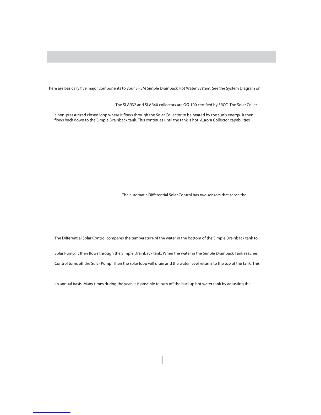
OVERVIEW OF SYSTEM OPERATIONS
pages 17, 18 and 20.
1. AURORA SOLAR COLLECTOR -
tor is where the sun’s energy is harvested and is typically mounted on the top of your roof. Water is pumped through
exceed temperature and pressure design ranges for the Simple Drainback Systems.
2. SIMPLE DRAINBACK TANK - The Simple Drainback tank is usually located in the garage or in a closet inside your
home, alongside the existing conventional hot water tank. When the solar system is turned o, all of the water in
the closed loop drains into this tank where it is stored until the system is turned back on. Cold domestic where
water passes through a submerged copper coil heat exchanger it picks up the heat stored in the Simple Drainback
Tank and comes out hot. This preheated domestic water then enters the conventional water heater’s cold inlet.
3. CONVENTIONAL HOT WATER TANK - Operation of the conventional hot water tank will maintain your hot water
at desired temperatures for times when there is not enough solar energy available. Water is heated or preheated as
well as stored in this tank until used for domestic use. If the water is not hot enough, the traditional tank kicks on, and
heats the water to the desired temperature.
4. DIFFERENTIAL SOLAR CONTROL -
temperature of the water in the Storage Tank and how much heat is available in the Solar Collector. If heat is called for
and available, the Solar Control turns on the Solar Pump that circulates water in a non-pressurized closed loop
through both the Simple Drainback tank and Solar Collector.
5. SOLAR PUMP - This 115 Volt pump circulates the water in the closed loop from the Simple Drainback Tank, up
through the Solar Collector where it is heated, and then back down to the tank where the heat is stored.
that of the water in the Solar Collector. If the temperature of the water in the tank is less than the desired temperature,
and if it is substantially lower than the temperature of the water in the Solar Collector, the Solar Control turns on the
the desired temperature, or when there is no longer enough energy in the Solar Collector to heat the water, the Solar
process goes on continually throughout the day.
Typically, solar water heating systems are designed to produce between 70% - 90% of your total hot water needs on
thermostat, thereby producing 100% of your energy requirements from solar. With the combination of both the
conventional energy source and the solar, you will have an abundance of hot water with a minimal amount of fuel
being consumed from conventional sources.

4
Safety
SYSTEM SAFETY DEVICES
INSTALLATION INSTRUCTIONS
SAFETY PRECAUTIONS
Your system contains many protection devices. A pressure-temperature relief valve on the backup hot water tank ensures
that the water in the Tank does not over heat or over pressurize. The Simple Drainback Tank enables all the water in the
system from freezing even during power outage. The Automatic Control has a high temperature limit setting that prevents
the water from being overheated. A Drain/Fill Valve is located in the Simple Drainback Tank to give you the ability to
valve that ensures that the tank will not over heat or pressurize the entire solar loop, should the system fail. Your system is
designed to be maintenance free, and normally the system should be left alone as it is for continuous operation.
The information included in this manual gives the basic instructions regarding system design and system operation.
Always consult with the proper authorities or check with your local building department for the permit requirements and
codes applicable before you start the job. Installation should always be in accordance with both local and National Fire
Codes.
OPERATION SAFETY PRECAUTIONS - Even though the automatic control has
a high temperature limit set, be aware that solar heated water can be very
hot. Scalding can take place within several seconds when water tempera-
tures are 140°F or higher. Here are a few precautions that can be taken to avoid
injury:
• When working on the roof, always take care to avoid hazards such as over
head electrical wires or loose shingles. Secure ladders so they will not slip or
fall. Wear shoes with proper tread to prevent slipping on the ladder or
sloped roof areas.
• -
cal hook-ups, especially when water is present. It’s always a good idea to shut
there is water leaking from the tank.
• Because of possible temperatures over
piping must be insulated and isolated to prevent burns.
• DO NOT hook up or turn on any electricity to electric water tanks until they are
FILLED with water.
• For California installations, the tanks must be braced, anchored, or strapped to
avoid falling or moving during an earthquake. See instructions for proper
mento, CA 95814.
•
below code.
• Always make sure a mixing valve is installed on the hot feed line to the house.
The mixing valve should be set to no higher than 120°F.
• When
hand before entering the shower.
• When using the hot water at a faucet, check the temperature of the water
with a quick splash before immersing your hands.
1. INSTALLATION SAFETY PRECAUTIONS - There is no substitute for safety.
Always exercise extreme caution, care and good judgement when working on
or around a roof. Here are just a few installation precautions to keep in mind:
DANGER
!
BURN
HOT
Water temperature over 125°F can cause
severe burns instantly or death from
scalds.
Solar tank fluid may reach 180°F. Use
extreme caution when servicing.
Children, disabled and elderly are at
highest risk of being scalded.
Feel water before bathing or showering.
Use a tempering valve to limit the domestic
hot water outlet temperature. See manual.
Time/Temperature Relationships in Scalds
Temperature Time to Produce Serious Burn
120°F More than 5 minutes
125°F 1 1/2 to 2 minutes
130°F About 30 seconds
135°F About 10 seconds
140°F Less than 5 seconds
145°F Less than 3 seconds
150°F About 1 1/2 seconds
155°F About 1 second
5
Safety
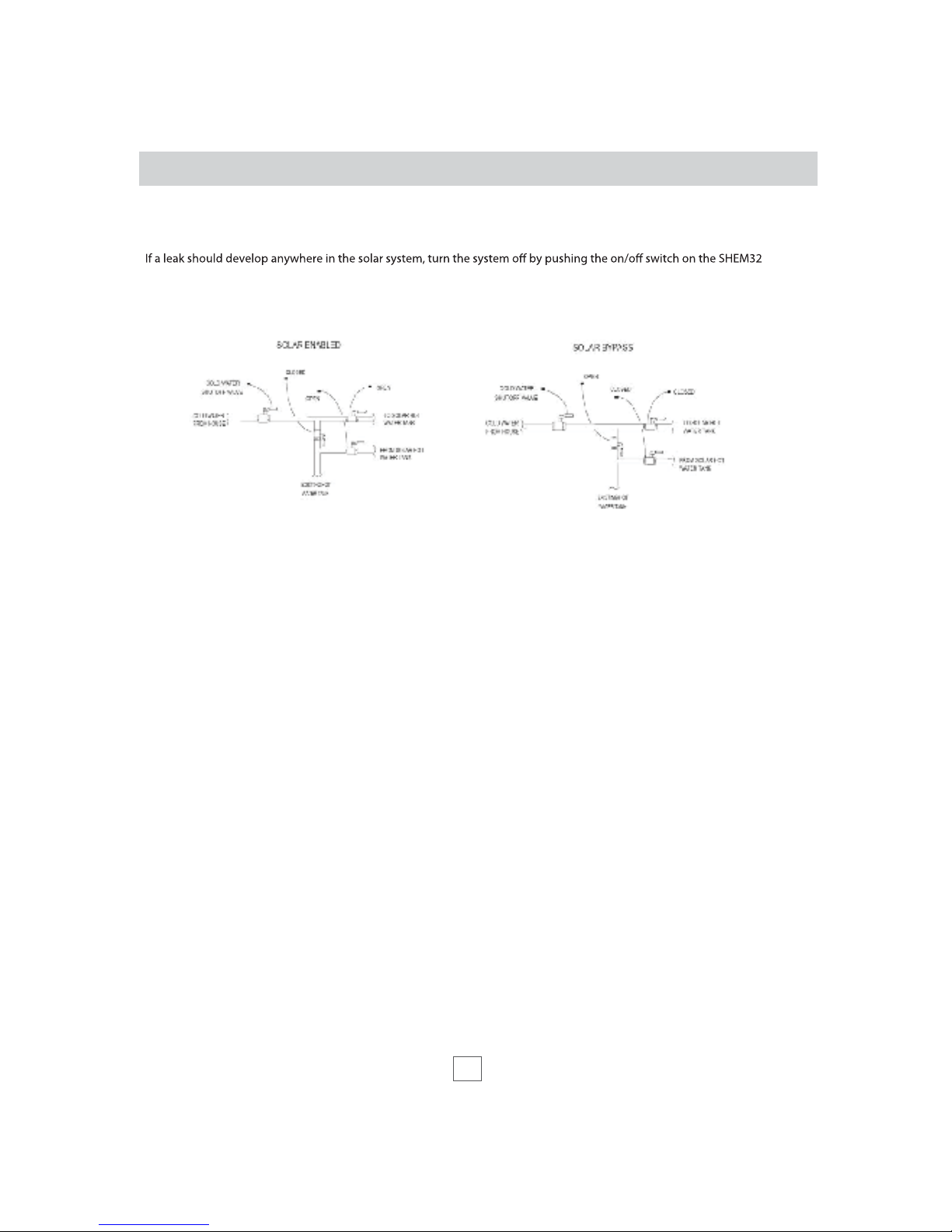
SAFETY PRECAUTIONS (CONT’D)
•
controller, or disconnect the power to the circulation pump, and then isolate the solar system utilizing the solar bypass
valves. Call your dealer right away for service. Diagrams #1 & #2 detail how to enable and bypass the solar system.
Diagram #1 Diagram #2
6
Installation Instructions
SIZING & ORIENTATION
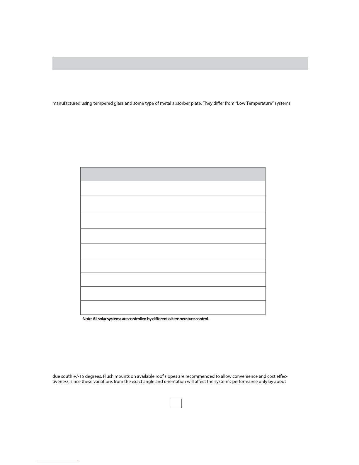
The vast majority of Solar Domestic Hot Water (SDHW) systems are comprised of “Medium Temperature” solar collectors
predominantly utilized in swimming pool heating applications. These systems are typically manufactured using plastic
resins. “High Temperature” systems are utilized to generate steam for industrial applications. Aurora collectors belong to
the “Medium Temperature” category.
Normally, only one or two Aurora collectors are needed for a SDHW system. The number of collectors is determined not
only by the amount of water that is needed, but also by the latitude of the installation and the collector’s orientation.
Typical domestic water use is approximately 20 gallons per person, per day.
The following table details a system sizing guide for a typical residential installation.
Normally, collectors are installed on roofs, as close as possible to the tank, to minimize heat loss through the pipes. The
pipes between the tank and the collectors MUST be insulated with at least 3/4” thick insulation, for the same reason.
The solar collectors must be located in a structurally sound area of the roof that will be exposed to the sun for the majority
of the day, all year round. No excessive shading is allowed.
The recommended angle of the collectors is the angle of the installation location’s LATITUDE. This angle is designed to
maximize solar absorption year round. A variation of +/- 15 degrees is acceptable. The orientation of the collectors must be
5%. Collector mounting should be capable of maintaining tilt and azimuth.
System
Model #
Tank
Capacity (gal)
Number
of Collectors
Collector
Type
SLAR-40
SHEM40-80SDB-XE
SHEM40-80SDB-XG
SLAR-32
SHEM64-80SDB-XE
SHEM64-80SDB-XG
SLAR-40 4’x10’
SHEM80-80SDB-XE
SHEM80-80SDB-XG
SLAR-40 4’x10’
SHEM120-80SDB-XE
SHEM120-80SDB-XG
SHEM160-80SDB-XE
SHEM160-80SDB-XG
SHEM200-80SDB-XE
SHEM200-80SDB-XG
SHEM64-120SDB-XE
SHEM64-120SDB-XG
SHEM80-120SDB-XE
SHEM80-120SDB-XG
SHEM96-120SDB-XE
SHEM96-120SDB-XG
SLAR-40 4’x10’
SLAR-40 4’x10’
SLAR-32 4’x8’
SLAR-40 4’x10’
SLAR-32 4’x8’
80
80
80
80
80
80
120
120
120
1
2
2
3
4
5
2
2
3
7
Installation Instructions
COLLECTOR MOUNTING
There are two basic roof-mounting methods:
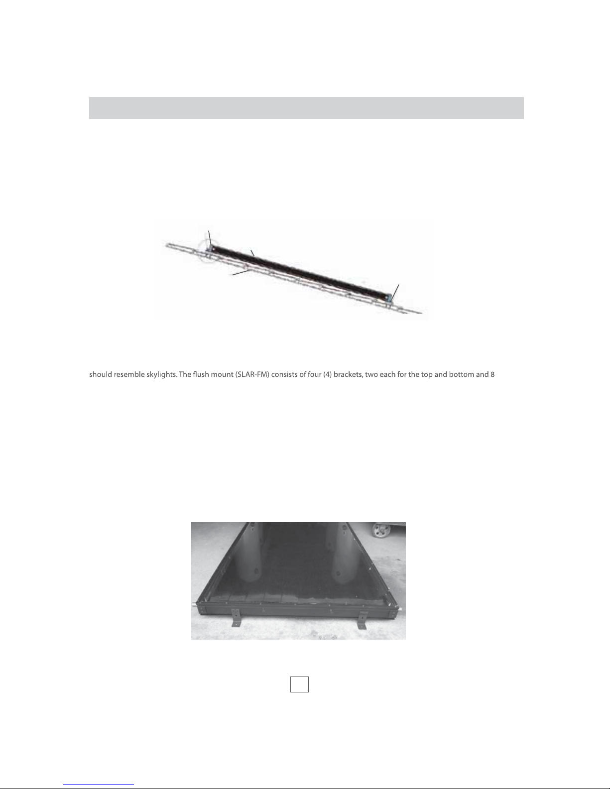
Flush Mount Installation - Parallel to the roof line, as illustrated below.
Flush Mount Installations are recommended when the roof’s slope conforms to the orientation requirements as stated
previously. This is the easiest and most aesthetically pleasing installation method. After the collector(s) are installed, they
self tapping screws.
1. Start from the bottom. The bottom side of the Aurora collector is marked by two weep holes placed about 20”
apart on the short anodized aluminum edge of the collector. When elevating the collector to the roof, make
sure that the “weep holes” are facing down. It is recommended to install the collectors vertically (length up the
roof’s slope).
2. Once the collector’s location is determined, anchor two (2) Mounting brackets to the roof using one (1)
stainless steel 3 1/2” x 3/8” lag bolt for each bracket. Pre-drill holes as to avoid splintering the rafters when in-
stalling long screws. Each bolt should be sealed using an appropriate roof sealant in order to prevent any
possible leaks from penetrating the roof members. The brackets should be spaced approximately 32” apart prefer-
ably directly into rafters or trusses. To insure that the drainback brackets system will drain properly the whole
collector must be canted toward the inlet 1/4” per foot.
Picture 1
Solar Collector
Mounting Bracket
Roof Truss
Mounting Bracket
Figure #1

8
Installation Instructions
3. Verify a secure connection to the trusses. If lagging directly into the roof trusses is not possible, secure a 2’ x 4’
wood beam perpendicular to the trusses, inside the attic, and anchor the bolts to this member. Again, verify a
secure connection into the new member. Attach the bracket to the collector using two stainless steel self tapping
screws. The collector should sit on the step of the bracket.
4.
5. For Mulitple Collectors: A 1” sweat coupling (or a 1” union) is required to join collectors.
a.) Mount the rst collector, and anchor.
b.) Locate and mount the brackets for additional collector. NOTE: It is a very tight and exact t, with less than 1/32”
tollerance.
c.) Clean and ux brackets. Mark with a pencil the proper location of sweat couplings on both manifolds.
d.) Slicd couplings on to the xed collector. Using a channel lock, one person should guide the manifold into the
coupling while using the channel lock to turn and properly locate the coupling. The other person is easing both
the top and bottom manifolds together in small alternating increments continually. The channel lock will help to
twist and properly move the coupling to your pencil marks. Without the twisting motion of the channel lock, it’s
dicult to properly locate the union to the pencil marks on the manifold.
e.) Solder both sides of coupling ONLY after collectors are properly aligned with the equally spaced couplings.
Angle Mount Installation -
below.
Angle Mount Installations involve positioning the collector(s) at an angle so that the upper part of the collector is higher
than the lower in reference to the mounting surface. The “angle mounting” is used on horizontal surfaces or on roofs that
slope in directions other than south ±15 degrees.
COLLECTOR MOUNTING (CONT’D)
Picture 2 Picture 3
AURORA
2 SELF
TAPPERS
3/8” x 3 1/2”
LAG SCREW
Figure #2
Solar Collector
Clip & 2 S.S. Screws
2 S.S. Screws
Nut & Bolt
Rod
U Channel
Figure #3
9
Installation Instructions
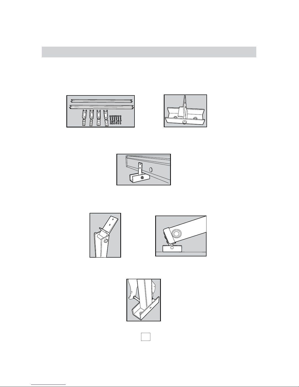
1. Use the Angle Mounting kit SLAR-TM (Picture 5). Connect the U-channels to the roof just like in the Flush
Mounting method. Assemble the mounting clips to both U-channels utilizing the provided bolts (Picture 6).
2. Screw the mounting clips to the BOTTOM part of the collector (the weep hole side) using two (2) stainless steel or
aluminum screws, each (Picture 7).
3. Assemble both rods and top mounting clips (Picture 8). Connect the clips to the collector’s top by stainless steel or
aluminum screws. (Figure #4)
4. Connect to the U-channels to the opposite side of the rod, using the provided nuts and bolts (Picture 9).
COLLECTOR MOUNTING
Picture 7
Picture 8
Picture 5 Picture 6
Figure #4
Picture 9

10
Installation Instructions
5. Lift the collector’s top with the assembled rod kits and anchor the U-channels to the roof, ensuring the proper angle
to the collectors (Picture 10).
-
sembly is not reduced.
COLLECTOR MOUNTING ONT’D
Picture 10
Penetrations of the building through which piping or wiring is passed shall not reduce or impair the function of the enclo-
sure. Penetrations through walls or other surfaces shall not allow intrusion by insects and/or other vermin. Required roof
penetrations shall be made in accordance with the applicable codes and also by practices recommended by the National
Storage tanks should not be placed directly on an un-insulated oor or concrete slab to avoid rusting problems associated
with condensation. The tank should be placed on a well-insulated pad with a minimum R-value of 10. An R-15 insulated
primary tank is recommended for all SHEM systems. If either the new solar storage tank or the existing backup tank need
additional insulation, an “Insulation Jacket” is recommended. (Frost King or equal). Be careful not to cover the thermostat
access panels or the P&T ports if additional insulation is required.
PLUMBING
CATCH PAN
DIAMETER OF TANK
PLUS 2" MIN.
MAX 2"
TO OPEN DRAIN,
LINE SHOULD BE A MIN.
3/4" ID AND SLOPED FOR
PROPER DRAINAGE
Figure #4, Catch Pan & Drain
The Simple Drainback Tank should be placed as near to the backup hot
water heater as possible. Do not place in an area where leakage will result
avoided it is recommended that an adequately drained, catch pan be
installed under the tank. See g. 4 for catch pan specications.
Make sure that all the components are accessible and easy to reach. Pro-
vide for clear access to the tanks, pump, mixing valve, controller, relay switch
and other key components. If a component in the potable water side of
the system may require future service or maintenance, make the connect-
ions with brass unions. Use only brass nipples and unions and copper and
brass ttings in plumbing the Simple Drainback Tank. The use of galvanized
ttings or nipples, di-electric unions, CPVC, PVC or other plastic pipe is pro-
hibited. Use 3/4” ID or larger copper pipe for the collector loop.
11
Installation Instructions
PLUMBING (CONT’D)
Hard copper connections to the city cold water supply line and the home hot water feed lines are recommended. The gas-
kets in standard water heater ex hose connectors can become brittle and compressed over time and begin leaking on the
water heater. If not detected in a timely manner even a small drip or leak may cause serious damage to the tank’s electrical
components or, in extreme cases, may cause the tank to leak from the outside in.
The solar system plumbing requires the ability to isolate the solar system from the city cold water supply line by means of
an isolating ball valve, #13 on system schematics.
The solar pump shall be pre-wired with a 42” line cord so that it can be plugged directly into the 115-volt receptacle at the
bottom of the SHEM32 dierential control. Pump Isolation Valves (#5 on schematics) are included above and below the
pump so repairs or routine system maintenance can be completed without introducing air into the system or draining the
Heat Transfer Fluid (water).
A high quality thermostatic mixing valve is a required component in all OG-300 certied systems and should be plumbed
at the outlet of the existing conventional tank with brass union connections for ease of future repair or replacement. The
specied mixing valve shall be the Watts model 70A-075 or equal. It should have an operating range between 95°F and
140°F. The mixing valve should be set to 120°F. The temperatures generated by your Simple Drainback System will vary
throughout the year. In the Northern Hemisphere the water temperature will be hottest in the spring and summer months
while cooler temperatures are to be expected from November through March. On sunny days system temperatures may
range from 110°F to 180°F depending upon the season and hot water demand. The mixing valve described above blends
the hot and cold water supplies to deliver hot water to your xtures at a safe, controlled temperature. A pressure relief
valve is required on the collector loop portion of the system. (#16 on system schematic) The drainback tank contains a port
specically for its installation.
WARNING: SCALDING CAN OCCUR WITHIN FIVE SECONDS WHEN WATER TEMPERATURES
APPROACH 140° F. THE MIXING VALVE SHOULD BE ADJUSTED BY THE INSTALLATION
CONTRACTOR TO PROVIDE WATER TO DWELLING FIXTURES AT NO MORE THAN 120°F
The 3/4” cold water supply line to the Simple Drainback Tank must be insulated with minimum 7/8" thick insulation for 3/4"
pipe insulation to a minimum distance of 5’ behind the storage tank, or to the wall if closer than 5’. When utilizing the
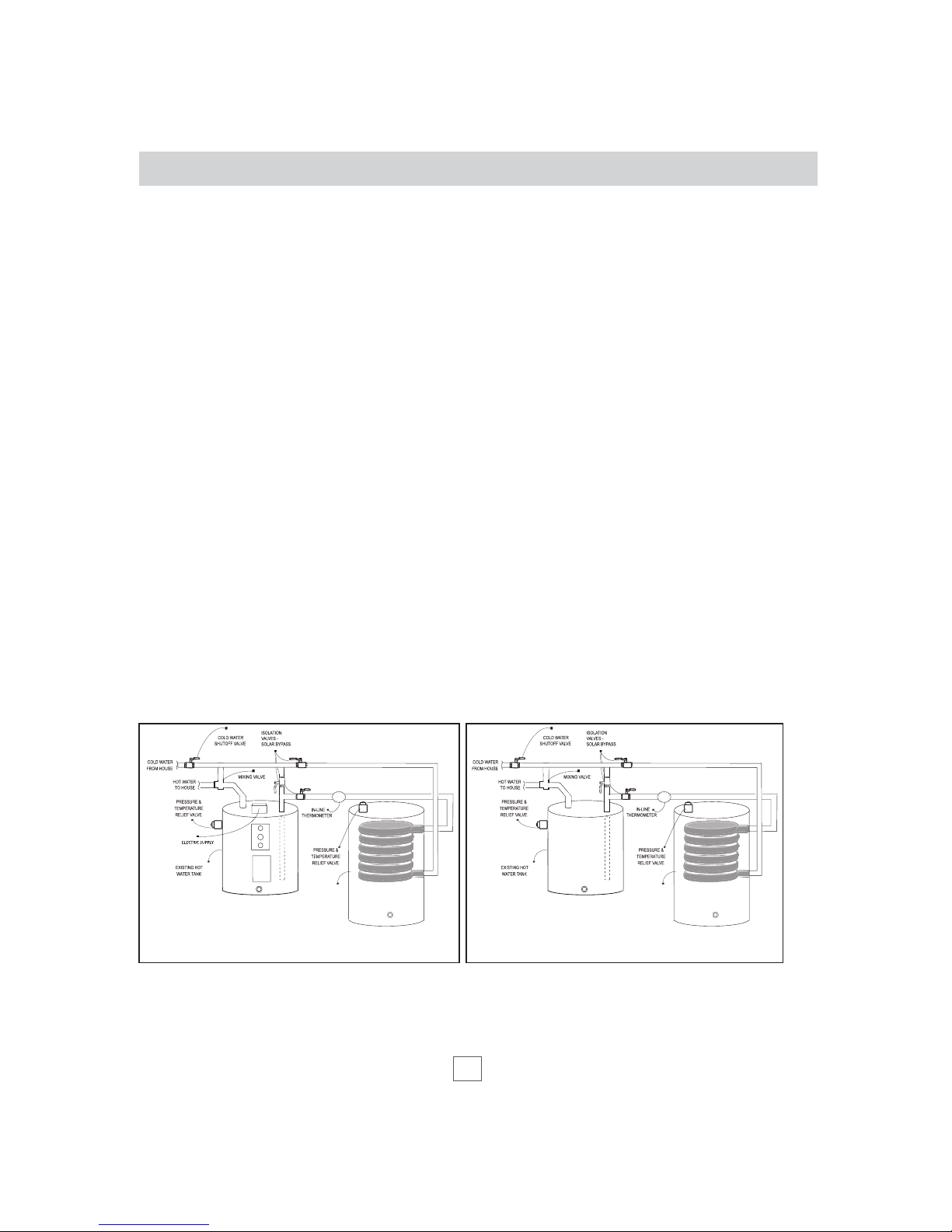
existing hot watertank, a solar bypass is required in all OG-300 certied systems, as illustrated in Figure #5 and #6.
Building materials adjacent to solar components should not be exposed to the elevated temperatures of the solar hot
water system. Insulation or separation of the solar system and building materials will prevent exposure to the elevated
temperatures.
SIMPLE
DRAINBACK
TANK
SIMPLE
DRAINBACK
TANK
Figure #6, Two Tank Conguration - GasFigure #5, Two Tank Conguration - Electric
12
Installation Instructions
PLUMBING (CONT’D)
CHECKING FOR LEAKS IN THE SOLAR
LOOP
Checking for leaks in the solar loop utilizes ths same proce-
dures used by plumbers when checking for leaks in new
construction. The solar loop must be isolated. Using a
compressor, pressurize the solar loop to 25 lbs. After 1 hour,
check to see that there has been no drop in pressure. In the
event of a leak, use a spray bottle with slightly soapy water to
locate the leak. After successfully completing the pressure test,
you may continue with insulating the solar loop.
PIPE INSULATION
insulation to minimize heat loss. The wall thickness of the pipe insulation should not be less than 3/4”. A 1” wall thickness
is required in all areas prone to annual hard freeze conditions. When it comes to pipe insulation the rule is simple: thicker
To the extent possible, slide the insulation material over the pipe without cutting or taping. All butt joints must be sealed
with contact adhesive. The use of rigid polyethylene pipe insulation is prohibited. All outdoor insulation should be
protected from moisture and ultraviolet deterioration by either paint or foil tape. All copper piping should be properly
supported, approximately every 6’. The support clamps should be installed in a way as to not compress the pipe insulation.
SHEM32 DIFFERENTIAL CONTROLLER AND SENSORS
as ∆t (Delta t). T1 is always located at the outlet manifold at the top of the collector. T2 always refers to the temperature at
the bottom of the tank. T3 measures the temperature of additional storage or the heat sink. The controller activates the
and the system “drains back”. This prevents summer overheating. The ∆t between T2 and T3 will activate a second pump.
very
important to verify that the high limit is set and engaged per manufacturer’s instructions. This will prevent overheating in
cases of high solar irradiation and low water usage. Please refer to the operation instructions of the controller for all
items relating to controller connections, settings, sensor location and sensor wiring.
13
Installation Instructions
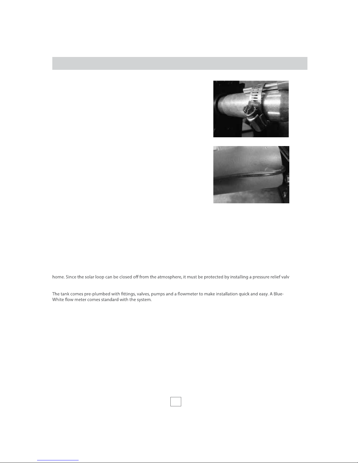
The T1 temperature sensor (black wire) should be securely fastened
to the manifold outlet of the collector. A stainless steel screw clamp
should be used (Figure #1). Sensor wire can be extended up to
165 feet with AWG #18 wire and up to 330 feet with AWG #14 wire.
The collector wires should be fastened to the T1 wire location on the
controller and secured with the wire strain reliever. After pressure
testing the system, insulate the manifold sensor wire outside of the
insulation so that it’s not touching the hot pipe (Figure #2). This will
ensure its safety from being damaged by the heated pipe.
THERMOMETERS
Locate two thermometers; one at the supply line and one on
the return line of the solar loop so that the temperature rise across
the collector can be determined. (#8 in the system schematics.)
DRAIN/FILL VALVE
Install a 3/4” drain ll valve (DV) in the drain port near the bottom of the
Simple Drainback Tank. The appropriate label should be placed
at the drain/ll valve.
SIMPLE DRAINBACK TANK
The Simple Drainback Tank and the solar pump should be installed as illustrated in the system schematic located on pages
17, 18 and 20. The system can be installed with an 80 or 120 gallon Simple Drainback Tank.
The Simple Drainback Tank is usually located in the garage or in a closet inside your home. It should always be located in a
non-freezing room. Its freeze tolerance limit is -10° F. This is where hot water is both stored and heated for use in your
(#16) as illustrated in the system schematic.
Figure #1
Figure #2

14
Installation Instructions
SYSTEM START-UP
Throughout the installation procedures outlined above, emphasis has been placed on the correct procedures for plumb-
ing and wiring the components and checking for plumbing leaks. Having completed these tasks it is time to start up your
Simple Drainback solar water heating system.
It is important to slope the lines going to and coming back from the collectors so water is able to drain. It is recommended
to maintain a 1/4” slope per foot. The piping from the tank always runs uphill and should drain freely, with no traps in
freeze vulnerable areas.
To insure that the drainback system will drain properly the whole collector array must be canted toward the inlet.
1. Connect a hose to the P/T Valve Port located at the top of the tank and place the other end in a 5 gallon bucket
or sink.
2. Connect another hose to the Drain/Fill Valve and the other end to a spigot and open the Drain/Fill Valve.
4. Close the Drain/Fill Valve and disconnect the hose at the top of the tank.
5. Disconnect the other hose from the spigot and place the loose end in an empty 5 gallon bucket.
6. Open the Drain Valve until the bucket is about half full (2 1/2 gal.) Then close it. This will allow volume in the
tank for expansion of the solar water as it is heated.
7. Disconnect the hose.
8. Install the P/T Valve in the P/T Valve Inlet.
9. Turn on the solar pump and let run for 3-5 minutes. Adjust the Ball Valve above the pump to throttle down the
number and size of Aurora Collectors in your system.
10. Check for any leaks along the pipe, pipe connections, or collector connections.
Collector Number Flowrate
Gal/min
SLAR-40 1 1
SLAR-32
2 1.4
SR-30
SR-30
TPP-SU2.4
TPP-SU2
TPP-SU2
1
2
2
3
2
1
2
1.5
1.1
1.1
VHP30
VHP30 1
2
.84
1.68
15
Installation Instructions
SYSTEM OPERATION (TWO TANK CONFIGURATION)
solar water heating system can (1) provide 100% solar operation during good weather, or (2) serve as a pre-heater to your
electric or gas backup water heater adding solar energy when and as available, or (3) 100% on utility power during
inclement weather.
Total Solar Operation -
trippers from the face of the switch. The solar bypass should be set to “enabled” as detailed in diagram #1 on page 5.
Preheat -
desired.
Total Utility Power -
can quickly damage the pump motor, shaft, bearings or impeller. The solar bypass should then be set to “bypassed” as
detailed in diagram #2 on page 4.

16
Installation
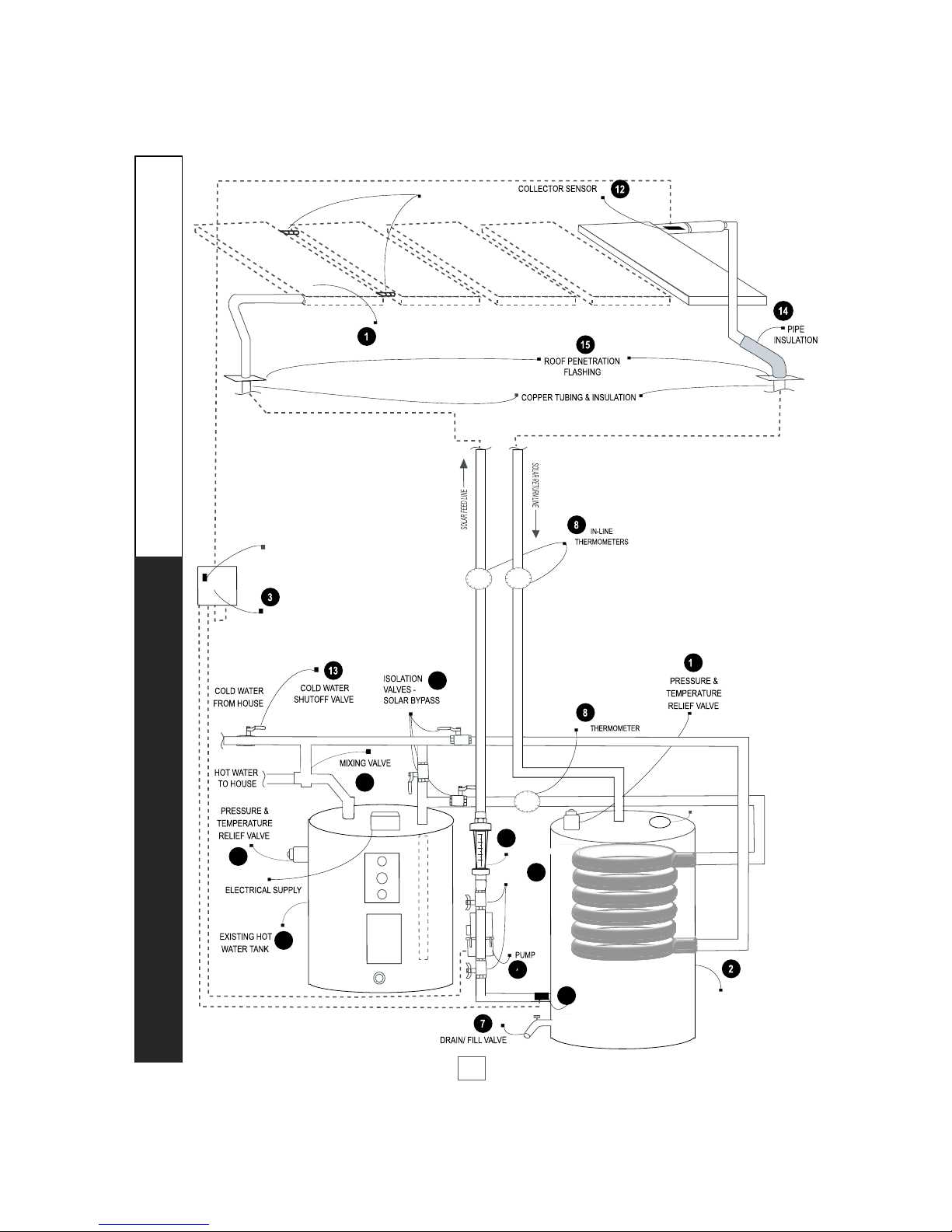
COMPONENTS PARTS LIST AND FUNCTION (TWO TANK CONFIGURA-
TION)
See the schematics on pages 17 & 18 for the location of the following lists of components. All piping,
1. Solar Collectors - Solene Aurora Collectors SLAR40 4 x 10, or SLAR32 4 x 8 with all copper chrome plated absorber
plate.
2. Simple Drainback Tank - SHEM 80DB or 120DB (80 or 120) Gallon Solar Storage Tank with heat exchanger. Tank
maximum temperature 220°F. Maximum working pressure 30psi. Heat exchanger maximum pressure 235psi.
Filled weight: 80DB-900 lbs., 120DB-1335 lbs.
3.
4. FlowMeter - Blue White 45500LB-12
5. Pump Isolation Valves - Amico 216A
6. Solar Pump - WILO STAR32F or STARS21F sized properly to accommodate head requirements.
7. Drain/Fill Valve -
8. Line Thermometers - Letro SL-2D In-Line Thermometer with temperature range of 50˚F to 220˚F
9. Mixing Value - Watts 70A-075 3/4” Mixing Valve tempers temperature of hot feed line to home and should be installed
at the outlet of the existing conventional hot water tank.
10. Pressure & Temperature Relief - Watts 100XL-4 P&T Relief Valve located on the solar storage tank opens at 150psi or
210˚F.
11. Tank Sensor – SHEM SG1.5 tank sensor with gray PVC cord.
12. Collector Sensor - SHEM SB 1.5 collector sensor with black silicone cord.
13. Cold Water Inlet Valve –
14. Pipe Insulation -
by the insulation manufacturer.
15. Roof Penetration Flashing -
for feed line to accommodate sensor wire.
16. Pressure & Temperature Relief – AKE Qingdao Anchor M&E WYA-20 P/T Valve located on Simple Drainback Tank,
open at 29psi or 210°F.
17. Solar Bypass - GV-075 3/4”
from the home directly into the existing tank.
18. Existing Hot Water Tank - Serves as a storage tank for hot water produced by solar system and backup heat source for
system. Must be of adequate size for the total demand using 100% backup. Must be listed and labeled by an accredited
listing organization. Filled weight of 50 gallon tank ~ 600 lbs.
DIFFERENTIAL
TEMPERATURE
CONTROLLER
120V
SIMPLE DRAINBACK
TANK
TANK SENSOR (T2)
6
PUMP
ISOLATION
VALVES
SOLAR
9
10
11
T1
HOT WATER
4
FLOWMETER
MG ANODE
SHEM DHW SYSTEM SCHEMATIC -XE ELECTRIC BACKUP TWO TANK
CONFIGURATION
ON/OFF BUTTON
17
18
5
6
17
SOLAR
COLLECTORS (1-5)
1” SWEAT COUPLINGS
OR UNIONS

DIFFERENTIAL
TEMPERATURE
CONTROLLER
120V
SIMPLE DRAINBACK
TANK
TANK SENSOR (T2)
6
PUMP
ISOLATION
VALVES
SOLAR
9
10
11
T1
HOT WATER
4
FLOWMETER
MG ANODE
SHEM DHW SYSTEM SCHEMATIC -XG GAS BACKUP TWO TANK
CONFIGURATION
ON/OFF BUTTON
17
18
5
6
18
SOLAR
COLLECTORS (1-5)
1” SWEAT COUPLINGS
OR UNIONS
19
Installation
COMPONENT LIFE EXPECTANCY
Installed and maintained properly, your Simple Drainback Solar Hot Water Heating System should provide many years of
trouble free, uninterrupted service. The main component of the system, the Aurora Solar Collector, is designed to last 25 to
30 years. Simple Drainback Tanks have a life expectancy anywhere from 15 to 20 years or more, depending greatly upon
regional wa
Control and Solar Pump life expectancies run from 5 to 10 years. As electrical components, they are susceptible to lightning
strikes or electrical surges. Valve life expectancy varies greatly depending on water quality and usage.
CONTACT INFORMATION
If you have any questions regarding the operation of your system, please contact your installing SHEM dealer.
SHEM DEALER CONTACT INFORMATION
Solar Heat Exchange Manufacturing
5009 Murray Road
Manhattan, KS 66503
(785) 320-5407
This manual suits for next models
16
Table of contents
Popular Water Heater manuals by other brands


Dux
Dux 21ENB5N owner's guide

Rinnai
Rinnai Infinity XR26ia installation guide

STIEBEL ELTRON
STIEBEL ELTRON UFP 5 h Operation and installation

Heatrae Sadia
Heatrae Sadia Express 7/1 Instructions and user guide

Riello
Riello 7200 Kombisolar 3S Installation, operation and maintenance manual

Unitary products group
Unitary products group SWAC-R22 Installation, operation & maintenance instructions


