Unitary products group SWAC-R22 Guide

Model SWAC
Self Contained Cooling/
Hot Water Heating Units
Supersedes: 145.26-IOM1 (708) Form 145.26-IOM1 (908)
UNIT MODEL
SWAC - R22
HOT WATER HEATING / ELECTRIC COOLING
INSTALLATION, OPERATION
& MAINTENANCE INSTRUCTIONS
Cooling Capacities
12,000, 18,000, 24,000, & 30,000 Btu/Hr.
Heating Coil Capacities
24,000-62,000 Btu/Hr.

JOHNSON CONTROLS
2
FORM 145.26-IOM1 (908)
This equipment is a relatively complicated apparatus.
During installation, operation, maintenance or service,
individuals may be exposed to certain components or
conditions including, but not limited to: refrigerants, oils,
materials under pressure, rotating components, and
both high and low voltage. Each of these items has the
potential, if misused or handled improperly, to cause
bodily injury or death. It is the obligation and respon-
sibility of operating/service personnel to identify and
recognize these inherent hazards, protect themselves,
and proceed safely in completing their tasks. Failure to
comply with any of these requirements could result in
serious damage to the equipment and the property in
IMPORTANT!
READ BEFORE PROCEEDING!
GENERAL SAFETY GUIDELINES
which it is situated, as well as severe personal injury or
death to themselves and people at the site.
This document is intended for use by owner-authorized
operating/service personnel. It is expected that this
individual possesses independent training that will en-
able them to perform their assigned tasks properly and
safely. It is essential that, prior to performing any task
on this equipment, this individual shall have read and
understood this document and any referenced materials.
This individual shall also be familiar with and comply with
all applicable governmental standards and regulations
pertaining to the task in question.
SAFETY SYMBOLS
The following symbols are used in this document to alert the reader to areas of potential hazard:
All wiring must be in accordance with published specications and must be performed ONLY
by qualied service personnel. Johnson Controls will not be responsible for damages/problems
resulting from improper connections to the controls or application of improper control signals.
Failure to follow this will void the manufacturer’s warranty and cause serious damage to prop-
erty or injury to persons.
DANGER indicates an imminently haz-
ardous situation which, if not avoided,
will result in death or serious injury.
CAUTION identies a hazard which could
lead to damage to the machine, damage
to other equipment and/or environmental
pollution. Usually an instruction will
be given, together with a brief expla-
nation.
WARNING indicates a potentially haz-
ardous situation which, if not avoided,
could result in death or serious injury.
NOTE is used to highlight additional in-
formation which may be helpful to you.

FORM 145.26-IOM1 (908)
3
JOHNSON CONTROLS
CHANGEABILITY OF THIS DOCUMENT
In complying with Johnson Controls policy for continu-
ous product improvement, the information contained
in this document is subject to change without notice.
While Johnson Controls makes no commitment to up-
date or provide current information automatically to the
manual owner, that information, if applicable, can be
obtained by contacting the nearest Johnson Controls
service ofce.
It is the responsibility of operating/service personnel as
to the applicability of these documents to the equipment
in question. If there is any question in the mind of oper-
ating/service personnel as to the applicability of these
documents, then, prior to working on the equipment, they
should verify with the owner whether the equipment has
been modied and if current literature is available.
Work on this equipment should only be done by properly trained personnel who are qualied to
work on this type of equipment. Failure to comply with this requirement could expose the worker,
the equipment and the building and its inhabitants to the risk of injury or property damage.
The instructions are written assuming the individual who will perform this work is a fully trained
HVAC & R journeyman or equivalent, certied in refrigerant handling and recovery techniques, and
knowledgeable with regard to electrical lock out/tag out procedures. The individual performing
this work should be aware of and comply with all national, state and local safety and environ-
mental regulations while carrying out this work. Before attempting to work on any equipment,
the individual should be thoroughly familiar with the equipment by reading and understanding
the associated service literature applicable to the equipment. If you do not have this literature,
you may obtain it by contacting a Johnson Controls Service Ofce.
Should there be any question concerning any aspect of the tasks outlined in this instruction,
please consult a Johnson Controls Service Ofce prior to attempting the work. Please be aware
that this information may be time sensitive and that Johnson Controls reserves the right to revise
this information at any time. Be certain you are working with the latest information.

JOHNSON CONTROLS
4
FORM 145.26-IOM1 (908)
TABLE OF CONTENTS
PREPARING TO INTALL UNIT....................................................6
IMPORTANT SAFETY RULES....................................................6
MEETING CODES ......................................................................6
UNPACKING ...............................................................................6
NORMAL INSTALLATION ...........................................................6
CLEARANCES ............................................................................6
WALL OPENING .........................................................................7
WALL SLEEVE ............................................................................7
EXTERIOR GRILL.......................................................................7
UNIT TO SLEEVE ATTACHMENT...............................................9
INSTALLING DUCTWORK........................................................10
FILTER RACK INSTALLATION FOR SIDE RETURN ............... 11
CONDENSATE DRAIN PIPING ................................................12
HOT WATER PIPING ................................................................12
ELECTRICAL CONNECTIONS.................................................13
INSTALLING ELECTRICAL WIRING ........................................ 13
SEQUENCE OF OPERATION ON HEATING CYCLE ..............14
START-UP CHECKLIST............................................................14
SYSTEM BALANCE..................................................................14
FAN SPEED ADJUSTMENT .....................................................15
MAINTAINING UNIT IN GOOD WORKING ORDER.................16
REFRIGERANT CHARGES ..................................................... 17
SCHEMATIC WIRING DIAGRAM ............................................ 17
WARRANTY POLICY................................................................19
SWAC models provide a complete air-conditioning and heating system as an all-in-one package. Specically de-
signed for convenient through-the-wall installation in residential low and high rise applications. The all-indoor design
eliminates the need for unsightly exterior equipment, thereby maintaining architectural esthetics.
All units are shipped completely wired and factory tested. The cooling section features enhanced refrigeration coils, a
thermostatic expansion valve for refrigerant control, and a high efciency Scroll or rotary compressor. Air circulating
fans are centrifugal, direct driven. The evaporator fan motor allows operation at three different fan speeds.
The standard unit may be operated on the cooling cycle at outdoor ambient above 60ºF.

FORM 145.26-IOM1 (908)
5
JOHNSON CONTROLS
To assure both safe and proper operation, please carefully follow the instructions in this manual to correctly install
this equipment.
INSTALLER! After installation, give the user:
- Operation & Installation Instructions - Warranty Information
USER! Your equipment installer should give you the above documents relating to your new heating/cool-
ing unit. Keep these as long as you keep this equipment. Pass these documents on to later purchases or
Users. Throughout this Installer’s Information Manual, we frequently use the word “you” when referring to
the person responsible for application, installation and service of your air conditioner. Please remember
to have only qualied service technicians perform these services.
IMPORTANT SAFETY NOTE: After installing this air conditioner, show the user how to turn off
the electricity to the unit. Point out control and switch locations for turning off the electricity.
Make sure user understands the importance of following all safety precautions.
LD13529

JOHNSON CONTROLS
6
FORM 145.26-IOM1 (908)
1. PREPARING TO INSTALL
A. Literature
After installing the unit; give this Installer’s Information
Manual, and the Warranty card to the end user. If you
need help on any of the installation instructions or other
matters relating to this equipment, contact the ofce
where you bought the unit. You may also refer to the
unit rating plate for a contact name.
2. IMPORTANT SAFETY RULES
Read and exactly follow these rules.
Failure to do so could cause improper
furnace operation, resulting in damage,
injury or death.
a) DO NOT install this equipment outdoors or in a
mobile home, trailer or recreational vehicle. It is not
design-certied for these installations. This furnace
is suitable for a home built on site or manufactured
home completed at nal site.
b) DO NOT install in a corrosive or contaminated
atmosphere.
c) DO NOT use this equipment for temporary heating
of buildings or structures under construction.
d) Always install duct system with this equipment.
Be sure duct system has external static pressure
within allowable operating range.
e) Completely seal supply and return air ducts to
the unit casing. Duct work must run to an area
outside the space containing the unit. Seal duct
work whenever it runs through walls, ceilings or
oors. See Section 11 for more information.
3. MEETING CODES
Before installing unit, make sure you know all
applicable codes. National, state and local codes
may take precedence over any instructions in this
manual. Be sure to consult:
- Authorities having jurisdiction over air-conditioning
and heating installations;
- Local code authorities for information on electrical
wiring.
4. UNPACKING
a) Check the unit for indications of damage in ship-
ment. Notify the Transportation company of any
damage and note the damage on the shipping
receipt.
Rough handling may dislocate internal
components.
b) Allow the shipping base to remain with the unit until
it is ready to be set in its nal location.
c) Rotate blowers to assure free movement.
d) The compressor is mounted on neoprene isolators
with metal spacing sleeves inside and secured
with nuts, which must be snug against the metal
spacer sleeves.
e) Check all refrigeration tubing to assure that it does
not rub against any other parts.
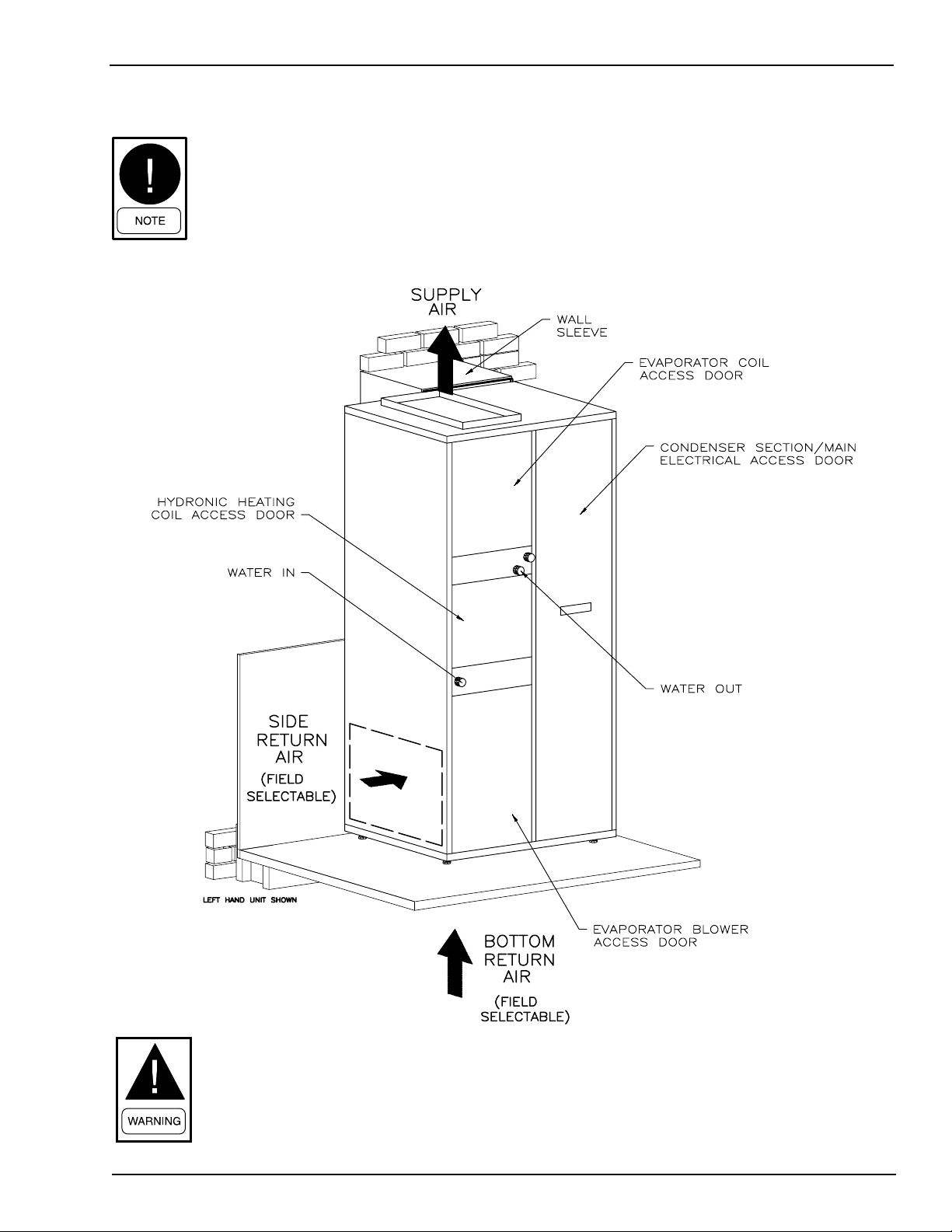
5. NORMAL INSTALLATION
This unit is designed for indoor installation adjacent
to an outside wall having an opening for condenser
air-ow. The air ow products must:
A. Discharge directly to the outside.
B. Discharge away from any obstructions, which
could cause recirculation of the hot condenser
exhaust.
6. CLEARANCES
This unit is designed for closet installation. No
clearance is required from the top, sides, or back
of the unit. A minimum of 1-inch clearance is re-
quired from the front to any combustible materials.
A combustible door may be placed 1 inch from the
front of the unit. When the door is open there must
be 30 inches clearance to any obstruction, to allow
sufcient access for service and the replacement
of parts. The unit shall not be installed directly on
carpeting, tile or other combustible material other
than wood ooring.

FORM 145.26-IOM1 (908)
7
JOHNSON CONTROLS
7. WALL OPENING
A nished opening in an outside wall is required
for intake and exhaust of condenser airow. The
wall opening required is 16” wide by 63” high for
S models. The wall opening must be ush with the
nished oor. Consult local ordinances for building
opening framing requirements.
8. WALL SLEEVE
A wall sleeve is required to nish the wall open-
ing. A factory-made wall sleeve is available as
an optional accessory for new construction. Use
a spirit level or plumb line to make sure that the
wall sleeve vertical anges, which must mate with
the back of the unit, are perfectly vertical. Correct
this if necessary, or the unit will not seal properly
against the wall sleeve. A roll of 1 inch wide x ¼
inch thick self adhesive rubber gasket is packed
in the blower compartment of the Skypak unit, to
be used for sealing between the wall sleeve and
the unit. Before moving the unit into nal position,
apply selfadhesive sponge rubber gasket to all
the mating anges on the wall sleeve, be sure to
apply gasket material to the divider panel ange
between the top and bottom sections of the wall
sleeve. Also apply gasket material to the top sur-
face of the horizontal lip at the bottom of the wall
sleeve.
9. EXTERIOR GRILLE
Finish the sleeve exterior with a factory supplied
intake and discharge grille.

JOHNSON CONTROLS
8
FORM 145.26-IOM1 (908)
LD13530
FIG. 1 - WALL SLEEVE ASSEMBLY

FORM 145.26-IOM1 (908)
9
JOHNSON CONTROLS
10. UNIT TO SLEEVE ATTACHMENT
Raise the unit by screwing down the three leveling legs,
until the ange at the bottom of the condenser is above
the ange at the bottom of the wall sleeve. Move the
unit forward until the unit contacts the wall sleeve and
makes a seal with the gasket on the wall sleeve. Then
lower the unit by means of the three leveling legs until
the unit bottom ange is resting on the wall sleeve bot-
tom ange, and the gasket is compressed. Then use the
front two leveling screws only to level the unit. The “S”
series units are secured to the wall sleeve by installing
two #10 x ½ inch self drilling sheet metal screws through
the ange standing up at the back of the unit top. These
two screws will screw into the wall sleeve.
Recommend Lintel
where required on
wall opening
Gasket
INSTALLATION WITH WALL SLEEVE
AND EXTERIOR GRILLE
UNIT/WALL SLEEVE BOTTOM CONNECTION
Grille flush
or recessed
from face
of wall
Units installed
without wall sleeve
must have partition
between inlet and
discharge air
Unit
Flange
Bottom of wall
opening flush
with floor
Caulk
Brick
Veneer
3. Lower unit to obtain tight seal between
wall sleeve and unit. insert attachment
screws thru blower outlet flange and
into wall sleeve.
2. Slide unit into contact with wall sleeve
unit flange must be inside wall sleeve.
1. Raise unit by means of leveling legs
unit Flange must clear bottom angle of
wall sleeve.
Unit Flange
Unit
Wall Sleeve Gasket
Unit Leveling Leg

JOHNSON CONTROLS
10
FORM 145.26-IOM1 (908)
11. INSTALLING DUCT WORK
Install all duct-work to meet current
standard:
• ASHRAE/NFPA 90, Standard for Installation of
Warm Air Heating and Air Systems.
• State, provincial, and local codes Failure to follow
these standards could reduce air ow or increase
air leakage, resulting in reduced system perfor-
mance or equipment damage. Properly size duct
work based on heat loss and heat gain calcula-
tions. Doing so assures:
• Good heating and cooling installations;
• Delivery of required circulating air.
Design duct systems within the maximum external
static pressure limits indicated in Table 1.
0.10.2 0.30.4 0.50.6 0.7
HIGH 560 530 500 460415 355 295
MED-HI 450 425 400 370335 300-
MED-LO 365 350 330 310270 --
LOW 315 290 275 ----
HIGH 705 375 635 585535 470 405
MEDIUM 650 620 585 540485 425-
LOW 520 510 490 465430 --
HIGH 920 880 840 800750 700 640
MEDIUM 775 760 735 705665 625-
LOW 580 565 550 530- --
HIGH 1060 1020 980 935885 830 770
MEDIUM 840 825 810 790765 730-
LOW 735 725 715 700- --
SWAC02412
SWAC03012
SWAC01212
EXTERNAL STATIC PRESSURE (in. wg.)
SWAC01812
UNIT MODELSPEED TAP
LD13530
TABLE 1 - SWAC FAN PERFORMANCE
SUPPLY AIR DUCT WORK
Duct attaching hardware must only be used on the
supply air outlet anges. Refrigeration tubing is located
under the top panel near these anges. Do not drill or
use screws in this area.
Supply air duct (plenum) connection
must be at least the same size as the
furnace supply air opening. Seal supply
air duct work to furnace casing, walls,
ceilings or oors.
RETURN AIR DUCT WORK & FILTERS
All return air entering the unit must be ltered. Refer to
Section 15 for lter size and instructions on installing the
lter rack. The return air lter must be supplied by the
installing contractor. The return duct should be sealed
to the unit casing and terminate outside the space con-
taining the furnace.

FORM 145.26-IOM1 (908)
11
JOHNSON CONTROLS
12. FILTER RACK INSTALLATIONS FOR
SIDE RETURN
CAUTION:Air lters are required to keep
the heating coil, air conditioning coil,
and blower motor clean. A lter frame
has to be eld installed, after snipping
out the prepunched opening in the side
of the unit.
Position the three-sided lter frame so that the short side
is towards the back of the furnace and the 1-inch duct
ange is facing outwards. The long sides of the frame
should be pulled slightly towards each other, so that the
continuous slip formed on the back of the frame clears
the opening in the cabinet. Push the frame towards the
back of the unit rmly until the short vertical part of the
frame clips onto the cabinet. Then insert the other verti-
cal side of the frame between the ends of the top and
bottom parts of the frame. This will keep the top and
bottom parts of the frame clipped into position.
If there is difculty getting the front vertical piece in-
stalled. Remove the entire lter frame and trim off any
burrs left where the opening was snipped out.
BOTTOM RETURN PLENUMS
When a bottom return plenum is used, snip out the
pre-punched 11 x 20 inch opening in the bottom of the
cabinet. Do not use this opening as a lter size. Bot-
tom return units are provided with a wire mesh lter
rack, suitable for use with replaceable lter media. The
required media size for this factory provided rack is 24”
X 28” X 1” thick.
If desired, panel lters may be installed in the bottom
return plenum or in the return air duct.
RECOMMENDED FLAT PANEL FILTERS SIZES FOR
BOTTOM RETURN APPLICATION
Unit Size Filter Size
1 Ton 12” x 20” x 1”
1-1/2 Ton 14” x 20” x 1”
2 Ton 16” x 25” x 1”
2-1/2 Ton 16” x 25” x 1”
There are no lters supplied with this unit. The installing
contractor must provide and install the recommended
size lters.
ALTERNATIVE FILTER ARRANGEMENTS
On 1 and 1 ½ ton units only, a lter frame to hold a 14
x 20 x 1 inch disposable lter may be tted to the front
of the blower compartment, in place of the access door.
The lter frame and a section of the return duct con-
nected to it must be easily removable, to allow room for
removal of the blower and motor assembly.

JOHNSON CONTROLS
12
FORM 145.26-IOM1 (908)
13. CONDENSATE DRAIN PIPING
The condensate drain pan is tted with a 3/4” NPT
female pipe tting which protrudes through the unit
casing. The 3/4” drain piping should be run horizontally
from this tting, until the piping is past the side of the
unit casing and not passing in front of any of the access
doors. Once the piping is clear of the unit casing, a trap
should be installed to prevent conditioned air from being
blown out of the drain line. The trap should be at least 2
inches deep with the outlet a minimum of 1/2 inch below
the inlet. The drain piping on the outlet side of the trap
should be pitched 1/4 inch per foot down towards an
open drain. Unions should be installed between the unit
and the trap, and on the outlet side of the trap to allow for
disconnecting the piping and the trap for cleaning out.
14. HOT WATER PIPING
The SWAC models are supplied with a 2- row hot water
heating coil. The water connections to the heating coil
project through the front of the unit cabinet, adjacent
to the heating section access door. For proper heating
operation, the orientation of the water in / water out must
be as follows: water-in = lower connection, water-out =
upper connection. The coil design is self-draining and
self-venting (provision for draining the water supply
line, and venting the water return line, must be eld
supplied).
The maximum design entering water temperature for
these units is 200ºF.
The threaded coil connection stubs are provided with
1/2” FPT ttings. Unions should be installed on both the
inlet and outlet piping (as close to the unit as possible),
to allow for disconnecting and removal of the entire unit.
There is no means for control of water ow included with
this unit. A slow-closing 2- way solenoid control valve,
or a circulating pump unit – capable of activation by a
low voltage pilot signal, must be eld provided
and installed.
The maximum design water ow through the heating
coil is 6 USGPM. Higher water ows may result in
excessive tube erosion, and a shortening of the coil
operating life.
Recommended water ow rate is 4-5 USGPM. This ow
range will provide the most economical balance between
heat output versus uid pressure drop.
HEATING COIL PERFORMANCE
(Capacity based on 65oF Return Air Temperature)
140ºF EWT
20
25
30
35
40
45
50
400 600 800 1000
CFM
Heating Capacity [Mbh]
GPM
6
5
4
3
160ºF EWT
25
30
35
40
45
50
55
60
65
400 600 800 1000
CFM
Heating Capacity [Mbh]
GPM
6
5
4
3
LD13533
HEATING COIL WATER PRESSURE DROP (WPD)
USGPM 3 4 5 6
FT H2O 4.9 8.4 12.9 18.4

FORM 145.26-IOM1 (908)
13
JOHNSON CONTROLS
15. ELECTRICAL CONNECTIONS
Check the voltage and phase listed on the unit rating
plate, before installation, to be sure the power supply is
correct. If the compressor fails as the result of installation
or improper voltage, the compressor is not replaceable
under warranty and the manufacturer will not be respon-
sible for the cost of replacement.
The minimum and maximum operating voltages, and
fuse sizes, are listed on the unit rating plate. The power
leads must be brought to the entry knockouts provided
in the unit control box through a customer supplied
fused disconnect switch placed within sight of the unit.
Knockouts are provided on the side of all units.
TABLE 2 - ELECTRICAL DATA
Model
#Voltage
Compressor Evaporator Fan Condenser Fan
Min.
CCT
Max.
Fuse
CCT.
Brkr.
Amp
Qty. RLA LRA HP FLA HP FLA
SWAC01212 208-230/1/60 1 @ 4.8 26.3 0.17 1.2 0.17 1.1 8.30 15
SWAC01812 208-230/1/60 1 @ 10.0 47.0 0.17 1.2 0.17 1.1 14.8 20
SWAC02412 208-230/1/60 1 @ 13.2 59.0 0.17 1.2 0.25 1.5 19.2 30
SWAC03012 208-230/1/60 1 @ 15.7 69.0 0.25 1.5 0.33 1.9 23.03 35
16. INSTALLING ELECTRICAL WIRING
Provide each unit with it’s own separate
electrical circuit, means of circuit protec-
tion and electrical disconnect switch.
Follow current National Electrical Code
ANSI/NFPA 70, CSA C22.1 C.E.C. Part
1, and state and local codes. Failure
to provide these shut-off means could
cause electrical shock or re, resulting
in damage, injury or death.
Install proper electrical grounding source to green wire
conductor in furnace junction box. Follow current Na-
tional Electrical Code ANSI/NFPA 70 and local codes,
or CSA C22.1 Canadian Electrical Code Part 1.
This equipment must have a proper elec-
trical ground. Failure to provide a proper
electrical ground could cause electrical
shock or re, resulting in damage, injury
or death.
Select a location for room thermostat that is away from
supply air registers, on draft-free interior wall, and not
near lights, television, direct sunlight, or other heat
sources.
FIG. 3 - FIELD WIRING DIAGRAM LD13534

JOHNSON CONTROLS
14
FORM 145.26-IOM1 (908)
17. SEQUENCE OF OPERATION ON
HEATING CYCLE
1 . Room thermostat calls for heat, connecting R and
W terminals.
2 . Hydronic Heat Circulating Pump/valve relay is
energized (eld supplied). Heating fan is energized
simultaneously with hot water ow interlock.
An electric heat / hot water heat thermo-
stat, which energizes the indoor fan dur-
ing the heating cycle, must be used.
3 . When the room thermostat is satised, terminals
R and W on the thermostat open, de-energizing
the hot water pump/valve interlock relay.
SEQUENCE OF OPERATION ON COOLING CYCLE
1 . Room thermostat calls for cooling connecting R
to Y terminals.
2 . The compressor and condenser fan start immedi-
ately on a call for cooling. Air circulating fan also
starts immediately with cooling operation.
3 . When the room thermostat is satised, terminal Y
on the module is de-energized.
4 . The compressor and condenser fan stop immedi-
ately when the thermostat is satised.
5 . The air circulating fan continues to run for an off
delay period of 100 seconds. The off delay on the
cooling cycle is factory set for maximum efciency.
Adjustment of this delay is not recommended.
18. START-UP CHECKLIST
Before starting furnace for the rst time, be sure you can
answer “Yes” to each of these questions:
1 . Is the unit level?
2 . Have you cleared away all loose construction and
insulation materials?
3 . Is unit installed within proper clearances to com-
bustible materials? See Section 6.
4 . Does electrical wiring follow current National
Electrical Code ANSI 70 or CSA C22.1 as well as
local codes? See Section 15.
5 . Is furnace electrically grounded? See Section
16.
6 . Is room thermostat properly installed? See Sec-
tion 16.
7 . Is duct work system correctly sized and sealed?
See Section 11.
8 . Are air lters in place and correctly sized? See
Section 12.
19. SYSTEM BALANCE
Blower speed taps are factory set for optimum heating
and cooling airow ranges. Refer to Table 3 for factory
blower speed settings, and minimum allowable cooling
airow.
If required, the Heating speed tap may be increased,
or reduced from the initial factory setting. The airow
rate through the hot water coil is the principal factor in
determining total heating output. Reducing the blower
speed will result in decreased heating output, but higher
discharge air temperature. Increasing blower speed will
produce maximum heat output, with lower discharge
temperatures.
At maximum heating airow, some duct
system congurations and supply regis-
ter locations may result in “cold blow”.
Installed system must be test run to ensure operation
with sufcient heating and cooling airow. Total system
static pressure should be measured and compared with
airow performance data shown in Table 1.

FORM 145.26-IOM1 (908)
15
JOHNSON CONTROLS
Measuring duct work static pressure
1. Place slope gauge near furnace where level, and
adjust scale to read 0.00 inches W.C
2. Insert one static pressure tap into the supply air
plenum. Insert other static pressure tap in return
air duct on the air entering side of the lter.
3. Connect pressure tap attached to supply air duct
or warm air supply plenum to positive pressure
side of slope gauge.
4. Connect pressure tap attached to return air duct to
negative pressure side of slope gauge.
5. Start blower
a. Heating speed blower can be run by jumping
terminals “R” and “G” on 24 volt terminal block
located on the Control Module.
b. Cooling speed blower can be run by jumping
terminals “R” and “Y” on 24 volt terminal block
located on the Control Module.
6. With blower running, read duct work static pressure
from slope gauge.
7. Duct-work static pressure should not exceed 0.3
inches W.C. in order to ensure proper volume of
air ow.
8. Remove jumper wire from 24-volt terminal strip.
Remove pressure taps and seal holes in duct-
work. Failure to seal holes could result in reduced
system performance.
LOCK ALL ELECTRICAL POWER SUP-
PLY SWITCHES IN THE OFF POSITION
BEFORE SERVICING THE UNIT. FAIL-
URE TO DISCONNECT POWER SUPPLY
MAY RESULT IN ELECTRICAL SHOCK
OR EVEN DEATH.
20. FAN SPEED ADJUSTMENT
Multi-speed direct drive motors are used in all units. To
modify the unit motor speed, the following steps may
be followed.
1) Locate the blower motor terminal block (TB3) inside
the electrical control box.
2) The blower motor leads are color-coded. Iden-
tify the appropriate motor lead for the desired
speed.
3) Cooling: Remove the existing motor speed lead
from the terminal connected to the cooling speed
relay (R2). Connect the desired speed to the spade
terminal. Move the unused motor lead to an open
terminal.
4) Heating: Remove the existing motor speed lead
from the terminal connected to the heating speed/
circulating fan relay (R1). Connect the desired
speed to the spade terminal. Move the unused
motor lead to an open terminal.
5) Reconnect power to the unit and test for proper
blower speed operation.
UNIT
MODEL
FACTORY BLOWER
SPEED SETTING
RECOM-
MENDED
MIN.
COOLIING
CFM
COOLING HEATING
SWAC01212 MED-HI MED-LO 300
SWAC01812 MEDIUM LO 450
SWAC02412 HIGH MEDIUM 600
SWAC HIGH MEDIUM 775
TABLE 3 - BLOWER SETTINGS

JOHNSON CONTROLS
16
FORM 145.26-IOM1 (908)
21. MAINTAINING UNIT IN GOOD WORKING
ORDER
WARNING: Follow these procedures
before inspecting furnace.
• Turn room thermostat to its lowest or off
setting.
• Wait at least ve minutes for furnace to cool if
it was recently operating.
• Turn off furnace electrical power; failure to do
so could result in injury or death.
Use only recommended replacements
parts. Failure to do so could cause im-
proper furnace operation, resulting in
damage, injury or death.
Perform periodic preventive maintenance once before
heating season begins and once before cooling sea-
son. Inspect, clean and repair as needed the following
items:
1. All electrical wiring and connections, including
electrical ground.
2. All supply air and return air ducts for obstructions,
air leaks and loose insulation.
3. Blower housings, motors and wheels, and air lters.
Blower motors do not require oiling.
4. Inspect evaporator and condenser coils for accu-
mulations of dirt and debris, and clean as required.
If the coils appear dirty, clean them using mild
detergent or a commercial coil cleaning agent.
Dirty or clogged evaporator coils cause low suction
pressures and lost cooling capacity.
With a clean condenser coil, the air temperature leaving
the condenser fan discharge should be approximately
33ºF above the outdoor air temperature. The saturated
condensing temperature should be approximately 38ºF
above the outdoor air temperature.
Outdoor Temp ºF Condensing Pressure (psig)
70 220
75 235
80 255
85 270
90 290
95 310
If the condensing pressure is higher than shown in the
table above, dirt in the condenser must be suspected.
To clean the condenser coil, remove the wall grille from
the outside and remove the accumulated dirt from the
air intake face of the coil using a brush and/or vacuum
cleaner. After cleaning, always remove all dislodged
dirt from inside the wall sleeve so that it will not be
sucked back into the condenser coil when the unit is
restarted.

FORM 145.26-IOM1 (908)
17
JOHNSON CONTROLS
Unit Cooling Capacity (BTU/HR.) R-22 Refrigerant Charge
SWAC**1212 2 lb.-14 oz.
SWAC**1812 3 lb.-14 oz.
SWAC**2412 4 lb.- 8 oz.
SWAC**3012 4 lb.-14 oz.
FIG. 4 - SCHEMATIC WIRING DIAGRAM LD13535
22. REFRIGERANT CHARGES

JOHNSON CONTROLS
18
FORM 145.26-IOM1 (908)
NOTES

FORM 145.26-IOM1 (908)
19
JOHNSON CONTROLS
LIMITED WARRANTY
Johnson Controls warrants this product to be free from defects in workmanship or material for a period of one year from date of original
installation or 18 months from date of shipment, whichever comes rst.
Johnson Controls obligation under this Warranty is LIMITED to repairing or replacing at our sole option, at our factory, any part thereof
which shall be returned to our factory, transportation charges prepaid and which on examination proves to have been thus defective
under normal domestic use not exceeding the fuel rating. The defective part should be returned through a qualied servicing dealer.
Upon warranty determination, the replacement part will be shipped freight collect and assumes the unexpired portion of this Limited
Warranty.
When a defective part can be repaired or replaced, Johnson Controls shall not be obligated to repair the entire unit or any part thereof
other than the defective part.
This warranty applies only to the original homeowner, and is subject to the terms and conditions hereof.
COMPRESSOR – FIVE YEAR LIMITED WARRANTY
In addition to the One Year Limited Warranty, Johnson Controls warrants the compressor to be free from defects in workmanship or
material for a period of ve (5) years from the date of original installation. If a compressor fails during this ve year period, a new com-
pressor will be supplied. The customer will be responsible for freight costs from our factory for delivery of the replacement compres-
sor and also for the return of the defective compressor which may be required under the terms of the Warranty. Labor and any other
expense involved in replacing the compressor is not covered by this Warranty.
HEAT EXCHANGER – TEN YEAR LIMITED WARRANTY
In addition to the One Year Limited Warranty, Johnson Controls warrants the heat exchanger to be free from defects in workmanship
for a period of ten (10) years from the date of original installation. During this time, a new replacement heat exchanger will be furnished,
or at our sole option, a credit for the replacement heat exchanger may be allowed. Labor and other expenses involved in replacing
the heat exchanger are not covered by this warranty. This Warranty applies only to the heat exchanger and not to other parts of the
furnace, and only to the original homeowner, and is subject to the terms and conditions hereof.
LABOR AND COST NOT COVERED
This Warranty provides only replacement parts or credits, and does not provide for or cover any labor, shipping, handling or other costs
for service travel, servicing, removing, or installing any parts.
EXCLUSIONS
This Warranty shall be void if:
1. The unit is not installed by a licensed or otherwise qualied or contractor and in compliance with the Installation Manual, applicable
installation and good trade practices.
2. The defect or damage is caused by accident, abuse, negligence of any person or company, misuse, riot, ood, re or Acts of
God.
3. The unit is not operated and regularly serviced and maintained as called for in the Users’ Manual.
4. Damages are caused by operating the unit in a commercial or corrosive atmosphere containing any damaging or dangerous
chemicals.
5. The unit is modied or services in a manner not in accordance with the Installation Manual and Users’ Manual.
6. Components, replacement parts, or other accessories not compatible with the unit or not approved by Johnson Controls have
been used with or attached to the unit.
7. The defect or damage is not caused by Johnson Controls, or it arises from circumstances beyond the control of Johnson Controls.
8. The unit is installed outside the United States or Canada, or has been removed from the place where it was originally installed.
THIS WARRANTY IS IN LIEU OF ALL OTHER WARRANTIES, OBLIGATIONS OR LIABILITIES, EXPRESSED OR IMPLIED BY
EMPLOYEES OR REPRESENTATIVES OF JOHNSON CONTROLS. ALL STATUTORY, EXPRESSED OR IMPLIED WARRANTIES,
INCLUDING THE IMPLIED WARRANTY OF MERCHANTABILITY AND FITNESS FOR A PARTICULAR PURPOSE ARE HEREBY
NEGATED AND EXCLUDED. ANY CLAIMS FOR INCIDENTAL AND CONSEQUENTIAL DAMAGES, OR ANY OTHER DAMAGES
OR EXPENSES BEYOND THE TERMS OF THIS LIMITED WARRANTY ARE HEREBY EXPRESSLY NEGATED AND EXCLUDED.

Subject to change without notice. Printed in U.S.A.
Copyright© 2008 by Unitary Products Group. All rights reserved.
Form 145.25-IOM1 (908)
Supersedes 145.25-IOM1 (708)
York
PA
17405
P.O. Box 1592
York, PA
17405
Engineered Systems
Products
Group
Table of contents
Popular Water Heater manuals by other brands

Sun Bandit
Sun Bandit SB-30E-100200-3000 Installation and operation instruction manual

Lochinvar
Lochinvar Copper-Fin CB--CW 495 -745 Replacement parts list

Rheem
Rheem MPs Series Owner's guide and installation instructions

Enertech
Enertech WS036 Installation & operation manual

Viessmann
Viessmann VITOCELL 300B installation instructions

German pool
German pool DEX12 user manual

ThermoFlow
ThermoFlow Elex Mini Basic Series Installation Guide, User Manual, and Warranty Information

Lochinvar
Lochinvar Copper-Fin CW 986 Replacement parts list

Ariston Thermo
Ariston Thermo CKZ 30 HH operating instructions

Cipax
Cipax CPX 23032/-1 installation guide

clage
clage DSX Touch manual

Bradford White
Bradford White 45085E Installation & operating manual