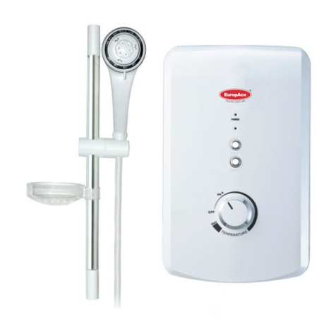
EuropAce EWH 5451T User manual

WATER HEATER
EWH 5451T
Instruction Manual
Thank you for purchasing EuropAce Oscillating Power Fan.
For safety purpose, please read this operating instruction manual carefully before using and
keep it for future reference.
MADE IN MALAYSIA
anual Reset
rated in
Water Heater
EWH 5451T
Thank you for purchasing EuropAce Water Heater.
future reference.

PART IDENTIFICATION
1
11
12
1
2
3
1) Front Cover
2) LED Indicator
3) Temperature Control Knob
4) Heater Base
5) Thermostat
6) Heater Tank
7) Water Outlet Connection
9) Main PCB Board
8) Rubber grommet
10) Water Inlet Connection
11) Pressure Relief Valve
12) Mesh Filter
13
9
10
4
5
6
7
11
12
8
13) Terminal Block

2
SAFETY INFORMATION
Products manufactured by us are safe provided they are installed, used and maintained in
refer to this manual if you have any doubt.
The appliance must be earthed. Improper grounding could cause electrical shock.
If the Heater begins to make an odd noise, smell or smoke.
Heater Indicator does not light up.
Water temperature cannot be controlled.
If found water leakage from inside.
When the Shower is used by someone such as child,elderly person, sick person and
and adjust the water temperature before using.
to protect the shower unit against possible damage.
to all exposed metal parts of other appliances and services in the room which in the heater
When removing the unit from package, small amount of water may found inside.
This is normal as the unit is tested during manufacturing process.
Note:
1.4
1.5
1.6
This Undersink Heater must be permanently connected to the direct main line supply.
A plug and socket is not recommended to be used.
For the correct size of wire conductor corresponding to di erent electrical loadings,
please refer to Table 1.
This Undersink Heater operates at a minimum wat ow rate of 3.0 liter/min and
maximum inlet water pressure of 6 Bar.
liter/min) to trigg ow switch.
abnormal rise in water temperature.
2.6

3
TABLE 1-ELECTRICAL LOADING TABLE
HEATER UNIT INSTALLATION
1) Installation instruction f
1.1) Install the Undersink Heater as close as possible to the main hot water dra points.
1.2) Leave a minimum of 5’’of clearance on all sides for servicing.
1.3) Remove plastic cover. (Fig. 3 )
1.4) Mount unit securely to wall by putting two screws through mounting holes.
Screws and plastic wall plugs for mounting are provided. (Fig. 4)
2) The unit is to be installed in a closed, frost-free room.The unit is to be installed vertically
(Hot water connection downwards).
3) The unit can be installed in any location, conceal in the ceiling, below washbasin or even wall mounted.
HEATER UNIT INSTALLATION DIAGRAM
Mounting hole (A)
Fig. 4
Fig. 1 Fig. 2
248mm
155mm
Fig. 3
83mm
Mounting hole (B)
Voltage Power Current
(AC) (kW) (A)
Conductor Size (csa)
mm Conduit Cable Flexible Cable
On/ O Fuse /
Switch (A) MCB (A)
240V
50/60 Hz
2.4 10.0 2.5 7 / 0.67mm 50 / 0.25mm 20 20
3.6
4.9 20.4 4.0 7 / 0.67mm 56 / 0.25mm 32 32
230V
50/60 Hz
3.3 14.4 2.5 7 / 0.67mm 50 / 0.25mm 20 20
4.5 19.6 2.5 7 / 0.67mm 50 / 0.25mm 32 32
6.0 25.0 4.0 7 / 0.85mm 56 / 0.30mm 32 32
220V
50/60 Hz
2.4 10.9 2.5 7 / 0.67mm 50 / 0.25mm 20 20
3.5 15.9 2.5 7 / 0.67mm 50 / 0.25mm 20 20
4.5 20.5 2.5 7 / 0.67mm 56 / 0.25mm 32 32
6.0 27.3 4.0 7 / 0.85mm 50 / 0.30mm 32 32
5.5 25.0 4.0 7 / 0.85mm 56 / 0.30mm 32 32
(Malaysia Modal)
15.0 4.0 7 / 0.85mm 50 / 0.30mm 20 20
3
TABLE 1-ELECTRICAL LOADING TABLE
HEATER UNIT INSTALLATION
1) Installation instruction f
1.1) Install the Undersink Heater as close as possible to the main hot water dra points.
1.2) Leave a minimum of 5’’of clearance on all sides for servicing.
1.3) Remove plastic cover. (Fig. 3 )
1.4) Mount unit securely to wall by putting two screws through mounting holes.
Screws and plastic wall plugs for mounting are provided.(Fig.4)
2) The unit is to be installed in a closed, frost-free room.The unit is to be installed vertically
(Hot water connection downwards).
3) The unit can be installed in any location, conceal in the ceiling, below washbasin or even wall mounted.
HEATER UNIT INSTALLATION DIAGRAM
Mounting hole (A)
Fig. 4
Fig. 1 Fig. 2
248mm
155mm
Fig. 3
83mm
Mounting hole (B)
Voltage Power Current
(AC) (kW) (A)
Conductor Size (csa)
mm Conduit Cable Flexible Cable
On/ O Fuse /
Switch (A) MCB (A)
240V
50/60 Hz
2.4 10.0 2.5 7 / 0.67mm 50 / 0.25mm 20 20
3.6
4.9 20.4 4.0 7 / 0.67mm 56 / 0.25mm 32 32
230V
50/60 Hz
3.3 14.4 2.5 7 / 0.67mm 50 / 0.25mm 20 20
4.5 19.6 2.5 7 / 0.67mm 50 / 0.25mm 32 32
6.0 25.0 4.0 7 / 0.85mm 56 / 0.30mm 32 32
220V
50/60 Hz
2.4 10.9 2.5 7 / 0.67mm 50 / 0.25mm 20 20
3.5 15.9 2.5 7 / 0.67mm 50 / 0.25mm 20 20
4.5 20.5 2.5 7 / 0.67mm 56 / 0.25mm 32 32
6.0 27.3 4.0 7 / 0.85mm 50 / 0.30mm 32 32
5.5 25.0 4.0 7 / 0.85mm 56 / 0.30mm 32 32
(Malaysia Modal)
15.0 4.0 7 / 0.85mm 50 / 0.30mm 20 20

4
continue from “HEATER UNIT INSTALLATION DIAGRAM”
Fig. 5
Pressure Relief Valve must be
installed to inlet every time.
Note: When connecting the Pressure Relief Valve to the water inlet, please make sure the discharge nozzle is facing
downward .Connect a discharge pipe (PVC tube of dia. 8.0mm) to the discharge nozzle in a continuosly
downward direction and this pipe must be left open t rain exhaust or discharge pipe.
In abnormal condition where pressure gets higher than 6.0 bars, water will drip from this discharge pipe.
PLUMBING PROCEDURE
A) Connect Pressure Relief Valve to INLET of water heater . Use sealing tape for the connection
to prevent water leakage. DO NOT apply excessive force when tightening the Pressure Relief Valve.
B) Insert Mesh Filter Washer before connecting the incoming water supply to the Pressure Relief Valve.
C) If in any case, make sure to put the Mesh Filter between the heater unit inlet pipe (Pressure Relief Valve)
Note :
- When connecting the Pressure Relief Valve to the water inlet, please make sure the discharge nozzle
is facing downward. Connect a discharge pipe (PVC tube of dia. 8.0mm) to the discharge nozzle in a
continuously downward direction and this pipe must be left open to the floor drain exhaust or discharge
pipe. In abnormal condition where pressure gets higher than 6.0 bars, water will drip from this discharge
and incoming water pipe.
pipe.
4
continue from “HEATER UNIT INSTALLATION DIAGRAM”
Fig. 5
Pressure Relief Valve must be
installed to inlet every time.
Note: When connecting the Pressure Relief Valve to the water inlet, please make sure the discharge nozzle is facing
downward . Connect a discharge pipe (PVC tube of dia. 8.0mm) to the discharge nozzle in a continuosly
downward direction and this pipe must be left open t rain exhaust or discharge pipe.
In abnormal condition where pressure gets higher than 6.0 bars, water will drip from this discharge pipe.
PLUMBING PROCEDURE
A) Connect Pressure Relief Valve to INLET of water heater . Use sealing tape for the connection
to prevent water leakage. DO NOT apply excessive force when tightening the Pressure Relief Valve.
B) Insert Mesh Filter Washer before connecting the incoming water supply to the Pressure Relief Valve.
C) If in any case, make sure to put the Mesh Filter between the heater unit inlet pipe (Pressure Relief Valve)
Note :
- When connecting the Pressure Relief Valve to the water inlet, please make sure the discharge nozzle
is facing downward. Connect a discharge pipe (PVC tube of dia. 8.0mm) to the discharge nozzle in a
continuously downward direction and this pipe must be left open to the floor drain exhaust or discharge
pipe. In abnormal condition where pressure gets higher than 6.0 bars, water will drip from this discharge
and incoming water pipe.
pipe.

continue from PLUMBING PROCEDURE
5
- Connections to the Multi-point hot water system should be limited to 2 or at
the most 3 outlet usage points and they should be near to each other, e.g. in
the same bathroom but only ONE OUTLET POINTS IS TO BE USED AT ANY
ONE TIME. Extensive distance between the appliance and usage point(s) will
result not only loss but also slow response of obtaining the hot water at the
point(s) (fig.5).
-
TURN ON THE WATER MAINS TO DRAIN OUT ALL PLUMBING DIRTS BEFORE CONNECTING
THE WATER SUPPLY TO THE INSTANT HOT SHOWER, THE WATER SUPPLY TO THE WATER
HEATER MUST BE FREE FROM MUD AND DIRT. ALWAYS KEEP THE WATER SUPPLY TO THE
WATER HEATER FREE FROM MUD AND DIRT AT ALL TIME DURING USAGE.
THE WATER INLET AND OUTLET MUST BE INSTALLED CORRECTLY , OTHERWISE THE HEATER UNIT WILL NOT FUNCTION.
DO NOT APPLY PLUMBING CEMENT ON CONNECTION.WHENEVER NECESSARY, USE ONLY THREAD OR SEALING TAPE.
-
-
THE HEATER TANK MUST BE FILLED UP WITH WATER BEFORE TURNING ON THE ELECTRICITY SUPPLY
TO PREVENT ANY DRY BURNT DAMAGE TO THE HEATING ELEMENT. - CHECK IF ANY WATER LEAKAGE.
UNIT MUST BE INSTALLED IN A VERTICAL POSITION WITH THE WATER FITTINGS POINTING DOWN- WARD. DO NOT
INSTALL UNIT WHERE IT WOULD ROUNTINELY BE SPLASHED WITH WATER. ELECTRIC SHOCK MAY RESULT.
-
ELECTRICAL INSTALLATION
2
6.
5.
3.
2.
1.
4.
All electrical work must comply with national and applicable state and local electrical codes.
Remember to SWITCH OFF the mains before carrying out any electrical work.
Refer to TABLE 1 for the correct cable size.
Use double insulation cable of over 2.5mm .
Lead the power cable from MCB to a“ON/OFF”double pole Linked Switch having a contact
separation of at least 3mm in all poles outside the bathroom,then lead a cable to the terminal
block inside the Heater Unit. (Fig. 6)
This appliance must be earthed. Improper grounding could cause electrical shock.
Fig. 6
(*)
To ensure the power cord NOT
touch c e.
Fig. 7
(*)
A

6
continue from ELECTRICAL INSTALLATION
T FUNCTION.
OT
PROCEDURE :
Insert the wall embedded cable through Side Entry ‘A’ by
cord rubber holder and lead the cable to Cable Bracket ‘B’. (Fig. 7)
Connect the cable as following:
BROWN or RED -- LIVE (L)
BLUE or BLACK -- NEUTRAL (N)
GREEN or GREEN/YELLOW -- EARTH ( )
Clamp the cable to the correct position. CHECK IF THE WIRING CONNECTION IS CORRECT AND SECURE.
- Reinstall the cover.
When putting back the Front Cover, please take note of the procedure shown below :
The‘’live’’wires must be connected to the slots on Terminal Block marked L.
The‘’neutral’’wires must be connected to the slots on Terminal Block marked N.
The ground wire must be connected to the at marked with the
3.
4.
Method of Alignment When Replacing Front Cover
Fig. A Fig. B
R rew ‘A’
5.
Terminal Block
Position
this way
(Off Position)
cutting a hole at the
source
ground symbol. ( )
TEST RUN
Turn on the water supply and Stop Valve, the wat ow through the outlet.
Switch on the electrical supply. (LED indicator will light up in Blue Color)
Turn the Temperature Control Knob to‘ON’, the LED Indicator will light up in Purple Color, hot water will
ow out within a few seconds.The more Temperature Control Knob being turned in clockwise direction,
the hotter is the water.
LED Indicator function :
The shower bath, long bath, wash basin might not be hot enought even at the ‘MAX’position if
incoming water supply from the mains is too cold or the pressure of water is too high. In this case, you
may adjust the incoming cold water mixer valve to reduce the wat ow in order to get the desired
water temperature.
It is unnecessary to turn the Temperature Control Knob to“OFF”position when the Heater is not in use.
Explain to the user how the unit works and familiarise him or her with its use.
- Advise the user about possible hazards (high water temperature)
- Hand over these instructions,to be kept in a safe place.
5.
6.
1) BLUE - ON
2) PURPLE - POWER ON
3) LED OFF - POWER OFF
Position
this way
(Off Position)

MADE IN MAL
230Va.c. 4.5kW 50/60Hz
ELECTRICAL LOADING
TYPE
WATER CONNECTION
DIMENSIONS 155mm x 83mm x 248mm
WEIGHT
1/2’’ BSP MULTI POINT SYSTEM
1.5 Kg
ELECTRONIC POWER CONTROL
Min. INLET WATER PRESSURE
Max. INLET WATER PRESSURE
0.1 Bar ( 10kPa)
6.0 Bar ( 0.6MPa)
EN L
G
N1
T2
TRIAC
Manual
Reset
Thermal
Cut-Out
(2Poles)
Heater
Tank
Power ON/OFF
Temp. Control
RC CB/ POWER
Turbine Flow Switch
TR FS
Thermistor
Inlet
Outlet
ELECTRICAL SPECIFICATION
WIRING DIAGRAM
MAINTENANCE
MAINTENANCE
CLEAN THE FILTER REGULARLY
Read the section ‘ SAFETY INFORMATION ’
If any abnormal condiiton to the water heater, switch OFF the mains
for repair service. Special skill is required for repairing. NEVER try to repair the unit by yourself.
CLEANING PRECAUTION !
Do not use thinner, alcohol, petrol or any other organic solutions to clean the set. Use only damped
cloth with mild detergent.
supply and contact sales agent
Clean the Mesh Filter regularly to prevent blockage. When carrying out any work,
Note : Water heater must be permanently connected to the electricity supply through a Manual Reset
Thermal Cut Out (2 Poles) having a contact sepration of at least 3mm in all poles incorporated in
the circuit.

MADE IN MALAYSIA
Water Heater
EWH 5451T
Thank you for purchasing EuropAce Water Heater.
future reference.
Product Warranty
The Warranty Card is not provided in the product packaging. You can register the product
warranty online at our website https://www.europace.com.sg/ewarranty/ within 7 (seven)
days from the date of purchase. You will enjoy an additional 3 months of the product
standard warranty when you register online. Please produce your E-warranty registration
when requesting for repair and service at our Service Centres nearest to you.
In the event, if you are unable to register the product warranty online you must produce your
purchase receipt/tax invoice and such other documentary proof of purchase of the appliance
when requesting for repair and service.
Product Warranty Coverage
You may nd out your product warranty coverage at the link below before calling our Cus-
tomer Service Hotline (65) 6457 3678 or visiting our Service Centre.
http://europace.com.sg/ewarranty/src/cupload/settings_pd-
f/1/1-1-2c899-1563960978-WARRANTY-COVERAGE-19_0221.pdf
TERMS & CONDITIONS OF WARRANTY (THIS WARRANTY IS VALID IN SINGAPORE
ONLY)
Your appliance is warranted against faulty design, workmanship or materials for a period of
12 months unless otherwise stated from the date of purchase, subject to the following terms
& conditions herein below:-
1) That the owner shall register the product warranty online at our website www.eu-
ropace.com.sg within 7 (seven) days from the date of purchase.
2) That the appliance shall be used solely for domestic purposes and not for commercial
purposes or any other purposes whatsoever and used strictly under the instruction for
operation as provided by the manufacturers or the appliance.
3) That if any time during the warranty period any part or parts of this appliance is removed,
tampered, modied, adjusted, altered, handled or repaired in any way whatsoever by any
persons other than those authorized by Strategic Marketing (S) Pte Ltd, this warranty shall
immediately cease to be valid and become void.
4) That the owner shall produce the E-warranty registration or tax invoice/receipt and such
other documentary proof of purchase of the appliance to our satisfaction as we may deem
necessary when requesting for repair and service.
5) That our decision on all queries relating to complaints as to defects either of workmanship
or of materials shall be conclusive and the owner shall agree to abide by such a decision. Any
appliance or defective part which has been replaced shall become our property.
6) The terms and conditions of this warranty shall be contained exclusively in this document
and no other presentation of provision, either written or otherwise, regardless of the origin of
the same, shall be accepted as either adding or removing from these terms and conditions.
7) That this warranty shall cease to be valid and void if the appliance is exported or
relocated from Singapore.
8) That there shall be no removal, alteration, defacement, or made illegible/tampered or any
kind of the serial number on the appliance.
9) That the owner shall be fully responsible for the due delivery and collection of the appli-
ance for any work done according to this warranty. Transportation expenses incurred for
delivery or handling the appliance are chargeable to the owner.
10) Transportation and labour charges apply after the full parts warranty expires. Refer to
https://www.europace.com.sg/ewarranty/ for more information.

In addition to the above, this warranty shall be subjected to the following limitations and
exclusions:-
a)The appliance shall be warranted by STRATEGIC MARKETING (S) PTE. LTD. from date of
purchase only for a period of:-
10 years - Heating Element warranty applies to selected models of Storage Water Heaters.
- Tank Leakage warranty applies to selected models of Storage Water Heaters.
8 years - Motor warranty applies only to selected models of Stand Fans (Walk-in warranty).
10 years - Compressor warranty applies to selected models of Refrigerators.
6 years - Motor warranty applies only to selected models of Stand Fans (Walk-in warranty).
- Compressor warranty applies only to selected models of System Air Conditioners
and Portable Air Conditioners.
5 years - Compressor warranty applies to Refrigerators, Freezers, Wine Coolers, Portable
Air Conditioners & Casement Air Conditioners (Outdoor warranty). Transportation is
chargeable from the 2nd year to 5th year.
- Compressor warranty applies to Dehumidiers (Walk-in warranty)
- Motor warranty applies only to selected models of Stand Fans (Walk-in warranty).
3 years - Full parts warranty applies only to selected models of Air Puriers & selected
models of Dehumidiers (Walk-in warranty).
- Heating Element warranty applies only to selected models of Garment Steamers
(Walk-in warranty).
- Motor warranty applies only to selected models of Jet Turbine Fans & selected
models of Air Coolers (Walk-in warranty).
2 years - Motor and internal parts warranty applies only to selected models of Stand Fans,
selected models of Oscillation Power Fans & selected models of Air Puriers
(Walk-in warranty).
- Heating Element warranty applies to selected models of Electric Ovens &
selected models of Kettle Jugs. (Walk-in warranty)
- Motor warranty applies only to selected models of Jet Turbine Fans
(Walk-in warranty).
- Full parts warranty applies only to Wine Coolers of 34 Bottles & above.
1 year - Full parts warranty applies to *Lifestyle Products (cash & carry items), Small
Kitchen Appliances, Fans, Air Coolers, Wine Coolers of 20 Bottles & below, Mini
Bar Fridge (Walk-in warranty)
- Full parts warranty apply to Refrigerators, Air Conditioners & Freezers
(Outdoor warranty).
Check out the warranty coverage of your appliance at www.europace.com.sg
b) The owner waives all or any claims to compensation monetary or otherwise which
he/she may be entitled to and shall agree to accept any compensation whatsoever by
way of additional repairs or otherwise which we in our absolute discretion may deem t
to oer. The giving of compensation shall be subjected to the other provisions of the
warranty.
c) This warranty shall not be transferable, negotiable or assignable to any third party.
d) The warranty does not include transport delivery or handling charges incurred in the
transportation of the appliance to and from Strategic Marketing (S) Pte Ltd.
e) Damage caused during transit where the appliance is transported for servicing, repair,
or in relation thereof or connection therewith.
f) In respect of refrigerator and air conditioner only, upon the expiry of 12 months from
the date of purchase, this warranty will not cover transport, refrigerant and labour to
install a new compressor.

g) This warranty will not cover chemical cleaning, maintenance service, general service and
overhaul, which if conrm is chargeable.
h) Defects or fault in the appliance which has been used for commercial purposes or which
have been rented/leased or which have been otherwise subject to other than household
use.
i) Claims for damaged/missing parts after 3 days from the original date of goods received
will not be valid.
j) This warranty and the Replacement Scheme does not particularly cover damages and/or
defects arising from
• Usage of wrong electrical supply/voltage.
• Usage not according to the Instruction Manual provided by the manufacturers.
• Misuse, accidents, negligence, abuse, improper installation, or any manner of tampering.
• Normal wear and tear.
• Corrosions rusting or stains.
• Scratches, dents on the unit body, casing or paintwork of the appliance.
• Act of God, re, ood and civil unrest.
• We shall not under any obligation, legal or otherwise to repair this appliance or one to one
exchange if the same shall be required as a result of losses, damages, and malfunctions
arising from any of the causes mentioned in the paragraph.
k) All accessories, external parts and extruded parts such as front panel, casing, door, glass
cover, glass door, cable/cord assembly, batteries, adaptor, plug, remote control, control
knob, buttons, lter, UV lamp, oven tray, wooden rack, exhaust hose, xtures, panels, cover,
lid and lever, plastic parts, fan blades, blade guard, inner pots, brushes, water tanks, attach-
ments made of glass, plastic and/or porcelain, detachable parts, and other option items are
excluded from this warranty.
All services provided after the warranty period will be chargeable at standard rates deter-
mined by STRATEGIC MARKETING (S) PTE. LTD.
The terms and conditions of this warranty shall be varied except with the written and
express consent or agreement of Strategic Marketing (S) Pte. Ltd. While Strategic Marketing
(S) Pte. Ltd. endeavours to repair any defects after the warranty period, it is subject to avail-
ability.
It is hereby expressly provided that any liability of Strategic Marketing (S) Pte. Ltd. for any
loss or damage whatsoever arising from, relating to or in connection with the purchase of
the appliance shall not exceed the purchase price (excluding installation costs) of the appli-
ance. Similarly, Strategic Marketing (S) Pte. Ltd.’s liability for any breach of this warranty shall
be limited to the purchase price (excluding installation costs) of the appliance.
* Lifestyle Products - Garment Steamer, Humidier, Dehumidier, Air Purier, Mini
Bar-Fridge.
* Walk-in warranty - Customers are obliged to bring the warranted products to Strategic
Marketing (S) Pte. Ltd. Service Centre for repair/service during the warranty period.
Ver. 20 _0312
Scan QR Code for
the online Warranty
Registration

Ver. 20 _0312
System Split Aircons | Tel: 6858 0801| Email: systemac@strategic.com.sg (Twin City)
Refrigerators, Washing machines, Cookers & other major appliances |
RELATED PRODUCTS & MAIN CONTACT HOTLINE
Table of contents
Other EuropAce Water Heater manuals
Popular Water Heater manuals by other brands
Rheem
Rheem TRITON GHE80SU-130A quick start guide
Grant
Grant HPMONO/IND125 Installation & user's instructions

Bosch
Bosch Tronic 1000 T Installation and operating instructions

GSW
GSW Electric Water Heater P/N 61515 REV. G... Installation and operating instructions

Rommelsbacher
Rommelsbacher RT 350 instruction manual
Takagi
Takagi T-K1 Installation manual and owner's guide

Drazice
Drazice NADO 300/20v11 OPERATING AND INSTALLATION Manual

Buderus
Buderus SF300.5 Installation and maintenance instructions
GE
GE 47S06AAG Energy guide

A.O. Smith
A.O. Smith POWER VENT GAS Installation and operating manual

DeDietrich
DeDietrich UNO BSL 150 user manual

Wolf
Wolf SPU-2 Assembly instructions

