Solar Storm SS48ST User manual
SS48ST Commercial Tanning Booth

Solar Storm warrants all of our indoor suntanning equipment to be
free from defects in workmanship as follows:
LPI’s obligation under this warranty is limited to the repair and/or replacement of any defective part
without charge for that part, at LPI’s discretion, with the following limitations:
This warranty is extended only to the original purchaser appearing on the sales receipt and
is non-transferable.
This product is designed for use by one person at a time.
Only original OEM parts may be used.
All major repairs must be completed by an authorized service representative.
This warranty does not cover transportation charges on the parts.
Labor costs are not reimbursable for repair or replacement of items.
LPI disclaims any responsibility for transportation. LPI further disclaims any responsibility for injury
resulting from the failure of equipment or parts manufactured by LPI due to incorrect installation or
operation.
LPI shall not be liable for loss or damages caused either directly or indirectly from the use of its
products. This limited warranty does not extend to any products which have been damaged as a result of
accident, misuse, abuse, or as a result of service or modification by anyone other than an LPI
representative.
This warranty does not apply to any failure of parts or products due to alterations, modifications, misuse,
abuse, accidents, improper maintenance, or failure to follow the specified electrical requirements. Such
occurrences immediately VOID this warranty. THIS WARRANTY IS EXPRESSLY IN LIEU OF ALL
OTHER WARRANTIES, EXPRESSED OR IMPLIED, INCLUDING THE WARRANTIES OF
MERCHANTABILITY. No person, firm, or corporation is authorized to assume for us any other
liability in connection with the sale of these goods
THIS PRODUCT IS IN CONFORMITY WITH PERFORMANCE STANDARDS
FOR SUN LAMP PRODUCTS PER 21CFR878.4635 AND 21CFR1040.20. AS A
RESULT, THIS PRODUCT MUST BE USED IN CONJUNTION WITH
21CFR1040.20 APPROVED EYEWEAR AND COMPONENTS.
Serial numbers are located on the rails at the rear of the booth.
Commercial Tanning Bed Warranty
• 36 Months on parts- Including: Ballast, Contactors, & Timers.
• 6 Months on Acrylic
• 90 Days on Gas Springs
• 90 Days on Lamps
• 180 Days on Labor

2655 Inferno 160X 160w
Disconnect power cord before attempting to clean, re-lamp, or
engage in the maintenance of this product. This equipment must
be earth grounded.
DO NOT operate the tanning booth while wet or near water.
Solar Storm Tanning Booth Specifications/Info.
Model
Size
HxW”
Weight
(lbs.)
Voltage
(Volts)
Amps
(Rated)
Dedicated
Breaker
Amps
NEMA
Receptacle
Timer*
Solar
Storm
36
77x48
375
240
41 50
N/A - Hard-
Wired
See Electrical
Requirements
Digital
Danger: Ultraviolet radiation. Follow instructions. Avoid overexposure. As with natural
sunlight, overexposure can cause eye and skin injury and allergic reactions. Repeated exposure may
cause premature aging of the skin and skin cancer. WEAR PROTECTIVE EYEWEAR; FAILURE
TO MAY RESULT IN SEVERE BURNS OR LONG-TERM INJURY TO THE EYES.
Medications or cosmetics may increase your sensitivity to the ultraviolet radiation. Consult
physician before using sunlamp if you are using medications or have a history of skin problems or
believe yourself especially sensitive to sunlight. If you do not tan in the sun, you are unlikely to tan
from the use of this product.
Persons under the age of 18, the elderly, or fair skinned people who always burn easily and either
never tan or tan minimally should not use this equipment.
Untanned persons should not tan on consecutive days during their first week of tanning. Never tan
more than once a day. Tanning normally appears after the first few sessions and maximizes after
approximately four weeks. Tan once or twice per week thereafter to maintain appearance. Persons
already having a base tan may begin at advanced levels corresponding to the extent of their base tan.
Intended use statement: The LPI tanning beds and booths are indicated for the tanning of human
skin via ultraviolet light.
THIS PRODUCT IS IN CONFORMITY WITH PERFORMANCE STANDARDS
FOR SUN LAMP PRODUCTS PER 21CFR878.4635 AND 21CFR1040.20. AS A
RESULT, THIS PRODUCT MUST BE USED IN CONJUNTION WITH
21CFR1040.20 APPROVED EYEWEAR AND COMPONENTS.
Pre-Installation Planning
Before you begin to assemble your tanning booth, please read the following information.
Electrical Requirements
Your Solar Storm tanning booth will need to be hard-wired to a 50A circuit.
A qualified electrician will be needed to assist in fulfilling these requirements
per your local code.
ALL IMPROPER VOLTAGES MUST BE RECTIFIED WITH THE
CORRECT BUCK BOOSTER TRANSFORMER!
Failure to comply with Solar Storm’s electrical requirements will
VOID ALL WARRANTIES and will damage electrical components!
VERY IMPORTANT!
MUST READ!
Your Solar Storm Tanning Booth 240 Volt Model
REQUIRES a 50 Amp DEDICATED Circuit Breaker.
This means that your tanning booth is the ONLY
electrical device operating on that circuit breaker.
Additionally a very easy way of protecting your tanning booth
from potential electrical damage due to power surge or spikes is
to disconnect the unit when NOT in use.

This page intentionally left blank.
Solar Storm Tanning Booth Location Requirements
Make sure the room is well ventilated. Air from the room is used to cool your tanning booth, which
helps to ensure years of trouble free performance. Poor ventilation may cause the unit to overheat
and cause discomfort to the user as well. Place your tanning booth no closer than one foot from any
wall. Be sure that curtains, drapes, and other room furniture is not obstructing the airflow into the
end caps of the booth or out of the fan openings. Due to the nature of the booth, it is best to place it
in a corner, allowing enough room for the door to swing open.
Unpacking Instructions
Your tanning booth comes in three cardboard cartons: two for the stationary sections and one
for the door section.
Remove the three sections from the plastic bags. The door box contains the hardware box.
Inspect all items thoroughly for any visible damage. Report any such damage to your
Solar Storm Authorized Dealer immediately.
BOOTH ASSEMBLY INSTRUCTIONS
Proper assembly of your tanning booth requires two people.
Tools required – In addition to the supplied hex key, assembling the tanning booth requires an
adjustable wrench.
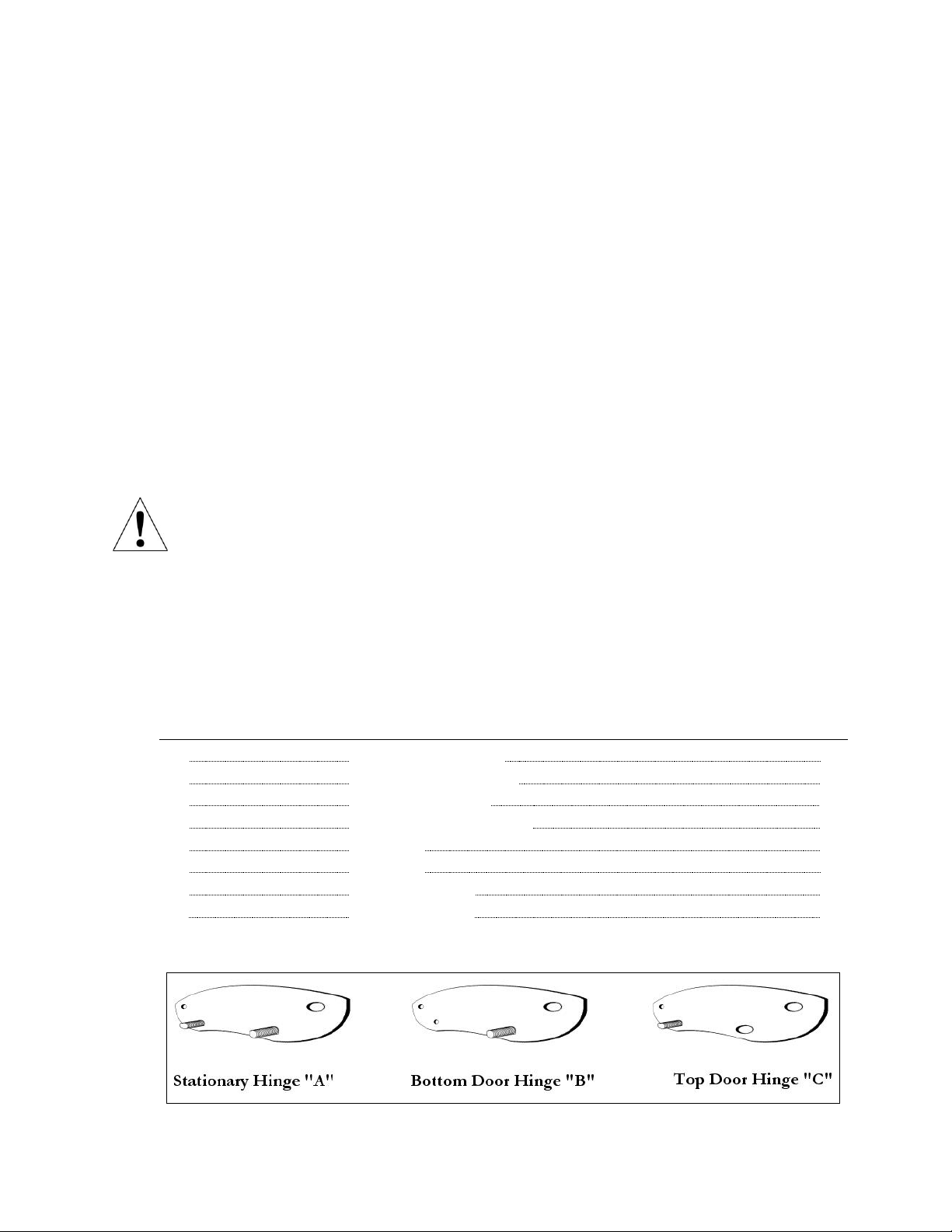
Parts List
Included Hardware
Item
Description
Quantity
A
Stationary Hinge
2
B
Bottom Door Hinge
1
C
Top Door Hinge
1
D
5/16 x 1 ½ Allen Bolt
8
E
Leveler
4
F
Caster
2
G
Allen Wrench
1
H
Leveler Nut
4

Included Hardware (continued)
Attaching Hinge to Bottom of Sections 1 and 2 – Figure 1a
Step 1. Lay sections one and two next to each other on a soft material (i.e. carpet) with the lamps
facing down, and with the male and female power cords aligned. Section one contains the timer and
main power cord. Section 2 has the short, inter-connecting power cords on both sides.
Step 2. Thread nuts “H” onto the levelers “E” then thread the leveler shafts into the end cap holes “3”
as shown in figure 1a. so that they protrude about 2 inches. Snug the nuts against the end caps. If
necessary, use an adjustable wrench on the levelers at the base of the threaded portion. DO NOT
OVER-TIGHTEN! BE CAREFUL NOT TO STRIP THE THREADS!
Step 3. During this step, make sure that the inter-connecting power cords are securely connected. Do
not pinch the cords between the rails of the two different sections. Have one person at the top end of
the unit, and another person at the bottom end. Both people need to raise the units in the center where
they meet in order to insert the guide bolts of hinge “A” into the “1” holes of the end caps at the
bottom end of the unit. The person at the top end of the unit can hold the two units up in position,
while the person at the bottom end threads bolts “D” through hinge “A” into the “2” holes of the end
caps. Use the supplied allen wrench to tighten these bolts. DO NOT OVER-TIGHTEN! Continue
supporting the two sections through the next step.

Attaching Hinge to Top of Sections 1 and 2 – Figure 1b
Step 1. Align the guide bolts of hinge “A” through the “1” holes in the end caps at the top end of the
units as shown in figure 1b.
Step 2. Thread bolts “D” through hinge “A” into the “2” holes of the end caps, and tighten with the
supplied allen wrench. DO NOT OVER-TIGHTEN!
Hard-
Wire

Attaching the Door to Bottom of Section 2 – Figure 1c
Step 1. Thread the casters “F” into the “3” holes in the end caps as shown in figure 1c. Tighten
with the adjustable wrench. DO NOT OVER-TIGHTEN!
Step 2. Align the guide bolt of hinge “B” through the “1” hole in the end cap at the bottom of
section 2.
Step 3. Thread one of the “D” bolts through hinge “B” into the “2” hole of section 2.
Step 4. Have one person hold the joined sections 1 and 2 in position to allow the other person to
thread the next “D” bolt through hinge “B” into hole “2” of section 3. Tighten the bolts with the
supplied allen wrench. DO NOT OVER-TIGHTEN!
Hard-
Wire

Attaching the Door to Top of Section 2 – Figure 1d
Step 1. During this step, make sure you do not pinch the cords between the rails of the two different
sections. Align the guide bolt of hinge “C” through the “1” hole in the end cap at the top end of
section 2 as shown in figure 1d.
Step 2. Thread bolts “D” through hinge “C” into the “2” holes of the end caps at the top end of
sections 2 and 3, and tighten with the supplied allen wrench. DO NOT OVER-TIGHTEN!
Now CAREFULLY position the unit upright by lifting the top end while securing the door so that it
does not swing open in the process. At this time, push the booth into its permanent location. Tighten
and/or loosen the levelers and nuts as necessary with an adjustable wrench to ensure proper footing of
the unit. The best spot to use an adjustable wrench on the levelers is at the base of the threaded stem.
BE CAREFUL NOT TO STRIP THE THREADS!
Making the Electrical Connection – refer to electrical requirements, page 5.
WARNING! Be sure electrical power is disconnected before connecting the
male/female inter-connecting cables.
Step 1. Securely connect all inter-connecting power cords that run between the three sections of the
unit.
The main power connection needs to be hard-wired by an electrician per the Electrical Requirements.
DO NOT CONVERT THE POWER CORD TO A TWO OR THREE PRONG
CORD, MODIFY THE CORD IN ANY WAY, OR USE ANY EXTENSION
CORD.
ENSURE THAT THE POWER CORD IS ROUTED SAFELY AWAY FROM
TRAFFIC AND/OR ANY HAZARDS.
AS RECOMMENDED FOR ALL ELECTRICAL APPLIANCES, THIS
TANNING BOOTH SHOULD NEVER BE OPERATED NEAR WATER
OR WHILE YOU ARE WET.
Pre-Tanning Guidelines
Your Skin
Before tanning, be sure your skin is free of any tanning oils or lotions, body lotions or cosmetics.
Cosmetics or medications applied to your skin may increase your sensitivity to ultraviolet light.
If you are taking any medication, or if you are especially sensitive to sunlight, we recommend
that you consult a physician before using this or any tanning equipment. It is also recommended
that you not shower or bathe immediately before using this tanning booth as it removes natural
body oils which protect your skin.
Your Eyes: All persons in the room should wear protective eyewear when lamps are on.
Recommended eyewear: Provided eyeshields or equivalent eyewear as defined under 21 CFR
1040.20. Other types of eyewear may not provide adequate protection. Failure to use protective
eyewear may result in severe burns or other eye injury. If discomfort develops, discontinue use
and consult a physician.
This Product complies with 21CFR878.4635 and must only be used in conjunction with
21CFR1040.20 approved eyewear and components.
DO NOT OPERATE the tanning booth near water or while you are wet.
Using the Tanning Booth
This tanning booth is designed for use by one person at a time. This tanning booth operates via a
timer. Determine the recommended exposure time according to your skin type. See chart below.
Recommended Exposure Times – Shown in Minutes
Skin Type:
Week 1
Week 2
Week 3
Week 4
I. Sensitive skin: burns easily and severely, does not tan
Not recommended for tanning!
II. Light: burns easily and severely, tans minimally
2 3 4 5
III. Normal: burns moderately, tans average
3 4 5 7
IV. Dark: burns minimally, tans easily and above average
4 6 8 10
MAXIMUM EXPOSURE TIME IS 15 MINUTES
ALLOW 48 HOURS BETWEEN TANNING SESSIONS!
Before tanning, refer to the recommended exposure chart above.

Timer Operation Section
Table of Contents
1. OVERVIEW.................................................................................................................................
1.1 SPECIFICATIONS..........................................................................................................................................
2. Configuration...........................................................................................................................
2.1 CONNECTING TO THE TANNING BED AND APPLYING POWER....................................................
2.2 SETTING PARAMETERS............................................................................................................................................
2.2.1 Setting the Address...................................................................................................................................
2.2.2 Setting Delay time.....................................................................................................................................
3. USING THE T-MAX® 005 AS A STAND ALONE TIMER...............................................................
3.1 STARTING A SESSION..............................................................................................................................................
3.2 PAUSING A SESSION................................................................................................................................................
3.3 CANCELING A SESSION..........................................................................................................................................
4. REMOTE SINGLE BED CONTROL..............................................................................................
4.1 WIRING.........................................................................................................................................................................
4.2 CONFIGURATION......................................................................................................................................................
4.3 SESSION CONTROL..............................................................................................................................................
5. USING THE T-MAX® 005 WITH A T-MAX®MANAGER OR T-MAX® MANAGER/PRO................
6. OTHER FEATURES.................................................................................................................
6.1 CLEAN ROOM.............................................................................................................................................................
6.2 LAMP HOURS.............................................................................................................................................................
6.3 CONNECTING THE AP900......................................................................................................................................
6.4 THIRD PARTY INTERFACE (TPI) MODE...............................................................................................................
6.5 EXTERNAL SPEAKER.................................................................................................................................................
7. FIGURES....................................................................................................................................
7.1 FIGURE A - FRONT AND REAR VIEW OF THE T-MAX® 005...........................................................................
7.2 FIGURE B - CONNECTINGTHE T-MAX®3A TO A TANNING BED WITH THE T-MAX®005.....................
7.3 FIGURE C - TPI (THIRD PARTY INTERFACE).......................................................................................................
©COPYRIGHT 1995-2006 By Applied Digital, Inc.
The information in this manual is believed to be correct. However, Applied Digital, Inc. assumes no responsibility for any errors herein.
This information is subject to change without notice, and should not be construed as a commitment by Applied Digital, Inc.
WARRANTY
This product is warranted against defective materials and workmanship for a period of two years from date of purchase. In the event
the product fails to perform, it may be returned; Shipping Paid, to the factory to be serviced or replaced at the factory’s discretion.
Applied Digital, Inc. will pay to ship the repaired or replaced product by the shipping means of our choosing. Returns will not be
accepted without a Return Authorization number assigned by the factory.
It is a condition of Sale that the user of Applied Digital Inc.’s products assumes all risk and responsibility of use and indemnifies Applied
Digital, Inc. against all damages. Applied Digital, Inc. is not liable for loss of profits, lost savings, special, incidental, consequential,
indirect or other similar damages arising from breach of warranty, breach of contract, negligence, or other legal action even if Applied
Digital, Inc. or its agent has been advised of the possibility of such damages, or for any claim brought against you by another party.
This warranty allocates risks of product failure between the purchaser and Applied Digital, Inc. Applied Digital Inc.’s hardware pricing
reflects this allocation of risk and the limitations of liability contained in this warranty. It is a violation of the stated warranty to cut or
modify the provided modular cables supplied with the T-Max R Series Timers. Connecting the T-Max R Series to third party timers not
approved by Applied Digital, Inc. also violates the stated warranty. Contact your dealer or Applied Digital, Inc. to determine if your third
party timer is approved by Applied Digital, Inc.
1
1
1
1
1
2
2
3
3
3
3
4
4
4
4-5
5
5-6
5
6
6
6
6
7
7
7
7
NOTE: Timer sections 1-7 are provided directly by Applied Digital,
Inc., the provider of the T-Max products and peripherals.he

1. OVERVIEW
Each T-MAX® 005 can manually control a tanning bed, be connected to a T-MAX® 3A
remote front desk control or be connected with many T-MAX® timers and T-MAX® Manager
or T-MAX® Manager/Pro to control many beds from a remote location. Operation is accomplished
via front panel controls.
1.1 Specifications
2. CONFIGURATION
2.1 Connecting to the Tanning Bed and Applying Power
A White header provides connection for power, lamps and fans. See Figure 1, Section 7.1
for wiring connections on this timer.
2.2 Setting Parameters
Note: If you are using a T-MAX® Manager or T-MAX® Manager/Pro and multiple T-MAX® timers,
remove power from the T-MAX® Manager or T-MAX® Manager/Pro and keep the power removed until
all parameter changes are complete.
1) Press and hold the Start/Stop and Up buttons simultaneously until a“.1” is displayed.
Release the buttons.
This is an indication that you are in the parameter mode. The numbers currently
displayed represents the parameter number that you can observe or change.
2) Press the Up or the Down Button until the parameter number that you want to observe
or change is displayed.
3) Press the Start/Stop Button. The current value for that parameter will be displayed and
be flashing.
The T-MAX® 005 will show a number with a period illuminated in the lower center of
the display. The number shown is the current value for that parameter.
For Lamp, Session Counts, etc. the value displayed can be as high as 9999. to display this
value, the T-MAX® 3A will flash two numbers-three times, then two numbers-three times,
pause, two numbers three times, two numbers three times, pause, etc. For example, if you
are checking lamp hours (Parameter 6) and the display flashes the number 53 three times,
Specications:
Current Draw 300mA
Dimensions Height – 3.5”
Width – 3.25”
Depth – 1.5”
Relays 220VAC @ 5A SPST Form A
Timer-1

Then 14 three times, pauses then repeats, then the total lamp hours stored in that T-MAX® 005 is 5314.
4) Press the Up and Down buttons to change the parameter to the desired value.
If you want to clear the value for that parameter, press the Up and Down buttons at the same
time until the display shows “.0”.
5) Press the Start/Stop Button.
The display will show the parameter number you just changed and a solid period in the lower
center of the display. You may now change another parameter by pressing the Up or Down buttons
until the parameter that you want to change is displayed. Repeat Steps 2-4 for each parameter you
want to change.
6) To exit the Parameter mode and make the T-Max® 005 available for the next session, press and hold both
the up and down buttons until the display shows a 0 with no periods displayed.
Table 1 - Parameter numbers for observing and changing parameters.
*If Manual Lockout is enabled, the T-Max® 005 cannot operate as a stand alone timer.
2.1 Setting the Address
Note: If you are using the T-Max® 005 as an independent timer, you don’t need to set the address.
1) Press and hold the Start/Stop and Up buttons simultaneously on the T-Max® 005 until a .1” appears
on the display. Release the buttons.
2) Press and release the Start/Stop button. A number will appear on the display and be ashing.
A period will be illuminated in the center of the display.
Param# Description Max # Default Notes
1 Address 255 254 Address of T-Max® 005
2 Beep Mode 1 0 Used for High Power beds. 0=Alarm only, 1=Alarm and Flip
3 Delay Time 10 0 Delay in minutes stored in the T-Max® 005.
4 Current Sense 1 0 For the T-Max® Sentry™ Option. 0=Disabled. 1=Enabled.
5 Session Counts 65535 0 Total session counts for T-Max® 005.
6 Lamp Hours 65535 0 Bulb hours for each bed.
7 Bed Hours 65535 1 Number of hours a bed is on.
8 Manual Session
Counts 65535 0 Counts the number of sessions the T-Max® 005 has run while in
Stand Alone Mode
9 Clean Room 1 1 0 = Clean Room Disabled. I = Enabled
10* Manual Lockout 1 0 0 = Stand Alone Enabled. 1 = Disabled
13 Cool Down Mode 10 0 0 = Disabled, 1- l0=Enabled. Time delay in minutes allowing bed to
cool.
15 Fixed Session Counts 65535 0 Counts number of sessions ran through theT-Max®005.
This value cannot be changed at all. Used as point of reference.
19 Third Party
Interface (TPI) Mode** 1 0 Used for input for timing systems other than the T-Max® Series.
Contact closure input. 0=Disabled; l=Enabled.
20 External Speaker 1 0 0 = Speaker on theT-Max®005, 1 = External Speaker will be used.
21 Pause Mode 1 0 0 = When session is paused, time will continue to count down. 1 =
When session is paused, session time will stop counting down.
22 Auto Bed Shut O 1 0 For T-Max® Intercom Systems Only. 0 = When timer is called bed will
stay on, 1 = When timer is called, bed will stu o automatically.
Timer-2

Pressing and holding the Up button will cause the display to count up. Pressing and holding the Down
button will cause the display to count down. Once the count reaches 100, the center period will ash rapidly.
This is an indication that you are over 99. For example, if the display shows a .2 with the period ashing, this
is address 102. The highest the display will count up is 255.
3) Press the Up or Down button until the desired address is displayed.
When setting the address remember 3 rules:
A) Set each T- Max® 005 to a unique address.
B) Do not set any address to 00.
C) Do not set any address over 100.
4) Once the desired address is displayed, press and release the Start/Stop button. The“.1” will appear on the
display. Nothing will ash.
5) To exit, press and hold both the Up and Down buttons together until the period goes away.
2.2.2 Setting Delay time.
1) Press and hold the Start/Stop and Up buttons simultaneously on the TMax® 005 until a “.1” appears on the
display. Release the buttons.
2) Press the Up Button until a “.3” is displayed.
3) Press and release the Start/Stop button.
A number will appear on the display and be ashing. A period will be illuminated in the center of the
display. This is the current delay time.
4) Press the Up or Down Button until the desired delay time is displayed. The highest delay time that can be
set on the T- Max® 3A is 10 minutes. If you want no delay time, set the display to 0. If you set the Delay Time
to 0, the session time will start immediately after the Start/Stop button is pressed.
5) Press the Start/Stop button. The “.3” will appear on the display. Nothing will be ashing.
6) To exit, press and hold both the Up and Down buttons together until the period goes away.
3. Using the T-Max® 005 as a Stand Alone Timer
3.1 Starting A Session
1) Press the Up or Down Button on the T-Mx® 005 until the desired session time is displayed. If the display
shows a 0, and you want to go directly to the maximum time, press the down button once.
2) Press and release the Start/Stop button to start the session.
If a delay other than 0 is entered, the delay will count down. A period on the lower right corner of the
display will ash rapidly. When the session starts, the period will ash at a once per second rate. If the
delay is set to 0, the session will start immediately. If you have a delay and want to energize the tanning
bed, press the Start/Stop button again.
Timer-3

3.2 Pausing A Session
To pause the session press the Start/Stop button. The ashing period on the lower right corner of
the display will stop ashing and stay illuminated. To restart the session, press the Start/Stop button
on the T-Max® 005. The period on the lower right corner of the display will resume ashing.
Note: The session time will continue to count down. The display will continue to update and
reect the remaining session time.
3.3 Canceling A Session.
To cancel a session, press the Start/Stop button to pause the session then press and hold the Up
button until the remaining session time showing on the display disappears.
4. REMOTE SINGLE BED CONTROL
Remote Single Bed Control is the ability to control a single T-Max® 005 from a remote location.
A T-Max® 3A is required for this conguration.
4.1 Wiring
Place a T-Max® 3A at the desired remote location. Wire the T-Max® 3A as shown in the T-Max® 3A
user’s guide.
Run the modular cable provided with the T-Max® 3A from the T-Max® 005 in the tanning room to
the remote T-Max® 3A. Connect the modular cable to one of the RJ-22 ports on each T-Max® 3A
(it does not matter which port the cable is connected to).
Note: If you are using the AP900 to connect the timers wireless, do not run the modular
cable. Connect the AP900s to the T-Max® 005 and the T-Max® 3A as described in the AP900
user’s guide.
4.2 Conguration
Set the address on the T-Max® 005 in the tanning room to “1” as described in section 2.2.1, and the
address on the T-Max® 3A to “0” as described in the T- Max® 3A user’s guide.
Note: When setting the address on the T-Max® 005, the power to the front desk T-Max® 3A
must be o.
Use the T-Max® 3A to set the Delay as described in the T-Max® 3A User’s Guide. Any delay time set
on the T-Max® 005 will be ignored.
4.3 Session Control
Starting a session
1) Press the Up or Dawn Button on the T-Max® 3A until the desired session time is displayed. Time
cannot be set from the T-Max® 005 in the room.
2) Press the Start/Stop button on the T-Max® 3A to start the session. If a delay other than 0 is set, the
delay will count down. A period on the lower right corner of the display will ash rapidly. When the
session starts, the period will ash at once per second rate. If there is no delay entered, the session
will start immediately.
Timer-4

Pausing During the Session
To pause the session press the Start/Stop button on the T-Max® 005 in the tanning room. The
ashing period on the lower right corner of the display will stop ashing and stay illuminated.
To restart the session, press the Start/Stop button on the T-Max® 005. The period will continue
ashing. The session cannot be paused from the T-Max® 3A in this conguration.
Note: The session time will continue to count down. The display will continue to update and
reect the remaining session time.
Canceling a Session
To cancel a session, press both the Start/Stop and Up buttons together on the T-Max® 3A. The session
cannot be canceled from the T-Max® 005 in the tanning room.
5. USING THE T-Max® 005 WITH A T-Max® MANAGER OR T-MaX® MANAGER/PRO
If you are using T-Max® 005s with a T-Max® Manager or T-Max® Manager/Pro, follow these
instructions for proper operation:
1) Set the address on each T-Max® 005 as described in section 2.2.1.
Note: If you have completed the auto addressing as described in your TMax® Manager user’s
guide, you do not need to address the T-Max® 005s manually. Skip this step.
Note 2: Set each T-Max® 005 to a dierent address. No T-Max® 005 should be set to address 0.
2) Using T-Max® Modular cables, connect the timers in a daisy-chain as shown in the T- Max® Manager
User’s guide.
Note: If you are using AP900s to connect the system wireless, do not run the modular cables.
Connect the AP900s to the T-Max® Manager and to the T-Max® 005 as described in Section 6.3
and in the AP900 user’s guide.
Note 2: Delay is controlled by the T- Max® Manager, the T- Max® Manager/Pro or the software
you are using if you are using a computer. It is not necessary to set the delay on the T-Max® 3A.
Refer to the T-Max® Manager or T-Max® Manager/Pro User’s Guide for operation.
6. OTHER FEATURES
6.1 Clean Room
Once the session time has elapsed, the display will show two solid periods only. This is an
indication that the room needs to be cleaned. To clear the clean room indication, press and hold
the Up button on the TMax® 3A in the tanning room until the two periods disappear and a “0”
appears. To disable the clean room feature, set parameter 9 to a 0. (Refer to Section 2.2)
Timer-5

6.2 Lamp Hours
To check and change Lamp Hours (or any other parameter), refer to Section 2.2.
6.3 Connecting the AP900
The AP900 allows you to connect the T-Max® 005 to the T-Max® System with out the need to
run cables throughout your salon. Connect an AP900 OEM to the RJ-11 modular connector
on the T-Max® 005. Mount the AP900 as described in the AP900 user’s guide.
6.4 Third Party Interface (TPI) Mode
The Third Party Interface (TPI) mode is used for connecting the T-Max® 005 timer to a timing
system other than the T-Max® Series.
Pins 3 and 4 on the RJ-22 modular port on the back of the I-Mix® 005 are used for TPI. Connect
pins 3 and 4 on the top RJ-22 connector to the relay output of your third party interface
controller. (Refer to Section 7.3, Figure C).
When the session is started, the third party timer will provide a contact closure to the input on
the T-Max® 005. When the session is started, the T- Max® 005 will show the maximum time stored
into that T-Max® 005 and the tanning bed will turn on. Once the session ends the front desk
controller will remove the contact closure from the TPI input on the T-Max® 005 and the bed will
turn o.
Any delay that the front desk timer uses cannot be eclipsed by the T-Max® 005. The customer
must wait the full delay time, in which case the bed will automatically come on.
If the session time on the T-Max® 005 eclipses, but there is still contact closure on the input, a
single period will be displayed on the T-Max® 005. Once the contact is removed from the TPI
input, then the next session can be started.
6.5 External Speaker
An external speaker can be connected to the T-Max® 005 to make the beep louder. A T-Max®
Speaker must be used. Connect the speaker to the connections shown in Figure A, Section 7.1,
Set parameter 20 on the T-Max® 005 to a 1 as described in Section 2.2.
Timer-6
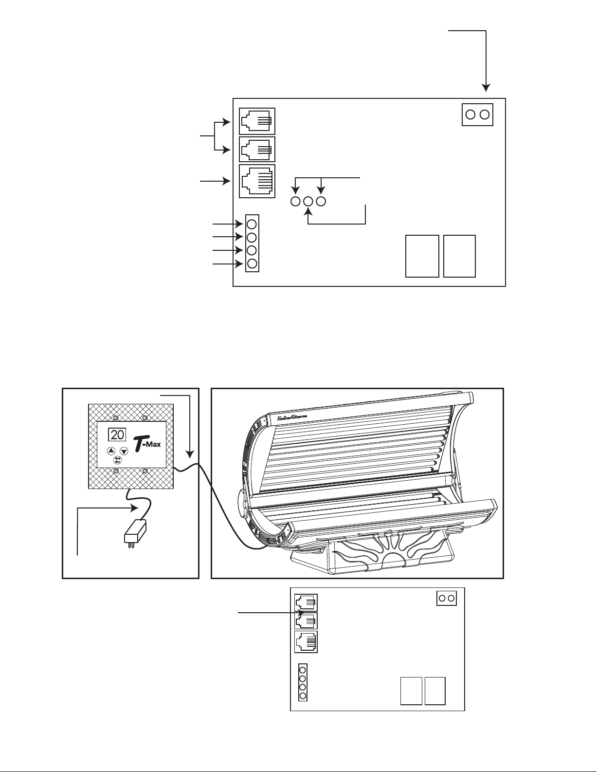
Figure A - Front and Rear View
Of the T-Max® 005
7. FIGURES External Start. Connect a momentary
push button to this terminal. This
allows the user to press a button
other than the Start/Stop botton on
the T-Max®005 to start a session.
RJ-22 Connections
RJ-11 (for connecting to the
AP900 wireless adapter)
Pin 1 - Fan AC Out
Pin 2 - Lamp AC out
Pin 3 - Neutral or L2
Pin 4 - AC In or L1
External Speaker
Positive
Rear View of the T-Max®005 PCB
7.2 Figure B - Connecting the T-Max®3A to a tanning bed with the T-Max®005.
Because the t-Max®005 is inside the tanning bed, you don’t
need a T-Max®3A in the room. Simply connect the 50’
modular cable to the RJ-22 connector on the tanning bed.
T-Max®3A at front desk.
50’Modular Cable
Connect to“PWR IN 9-12V”
7.3 Figure C - TPI (Third Party Interface)
Pin 3 and 4 are used for TPI.
Connect these two wires to
the relay of your third party
controller.
Parameter 19 must be set to
a 1 for TPI to work.
Timer-7
THE TANNING BOOTH SHOULD BE COMPLETELY SHUT DOWN AND
UNPLUGGED FROM POWER SOURCE BEFORE ANY CLEANING OR
MAINTENANCE.
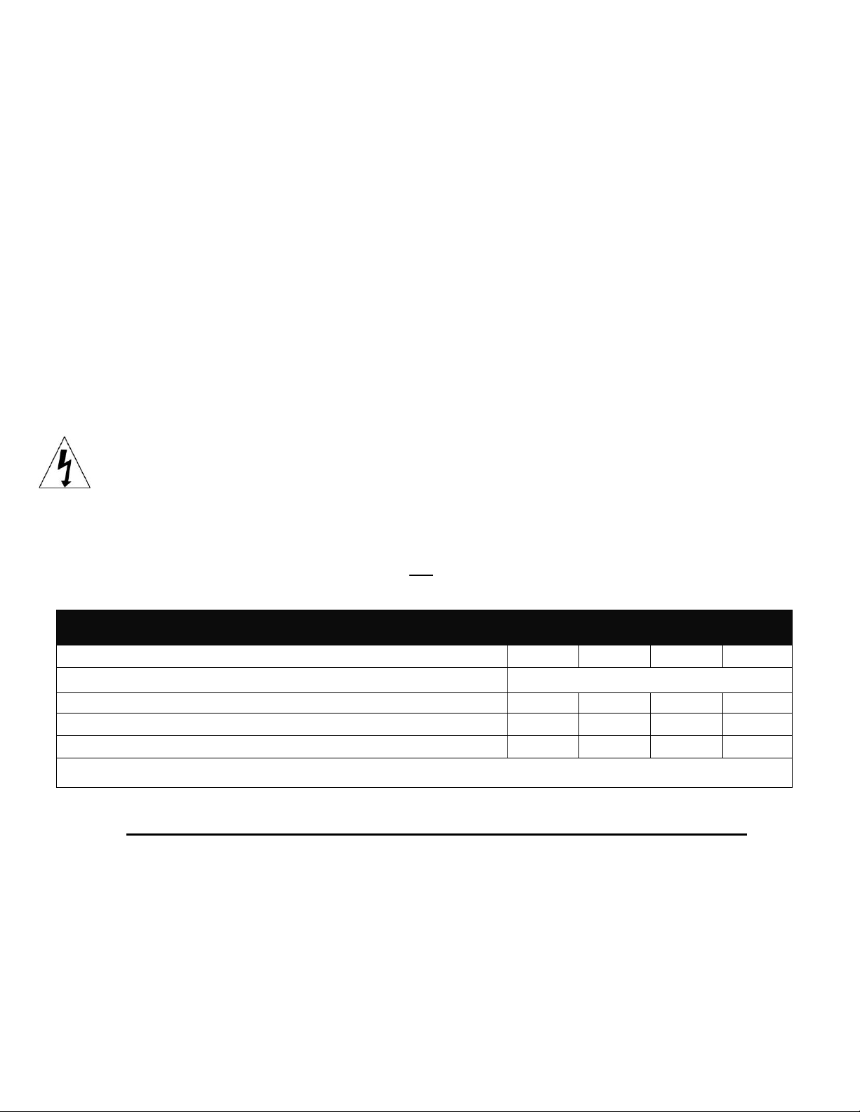
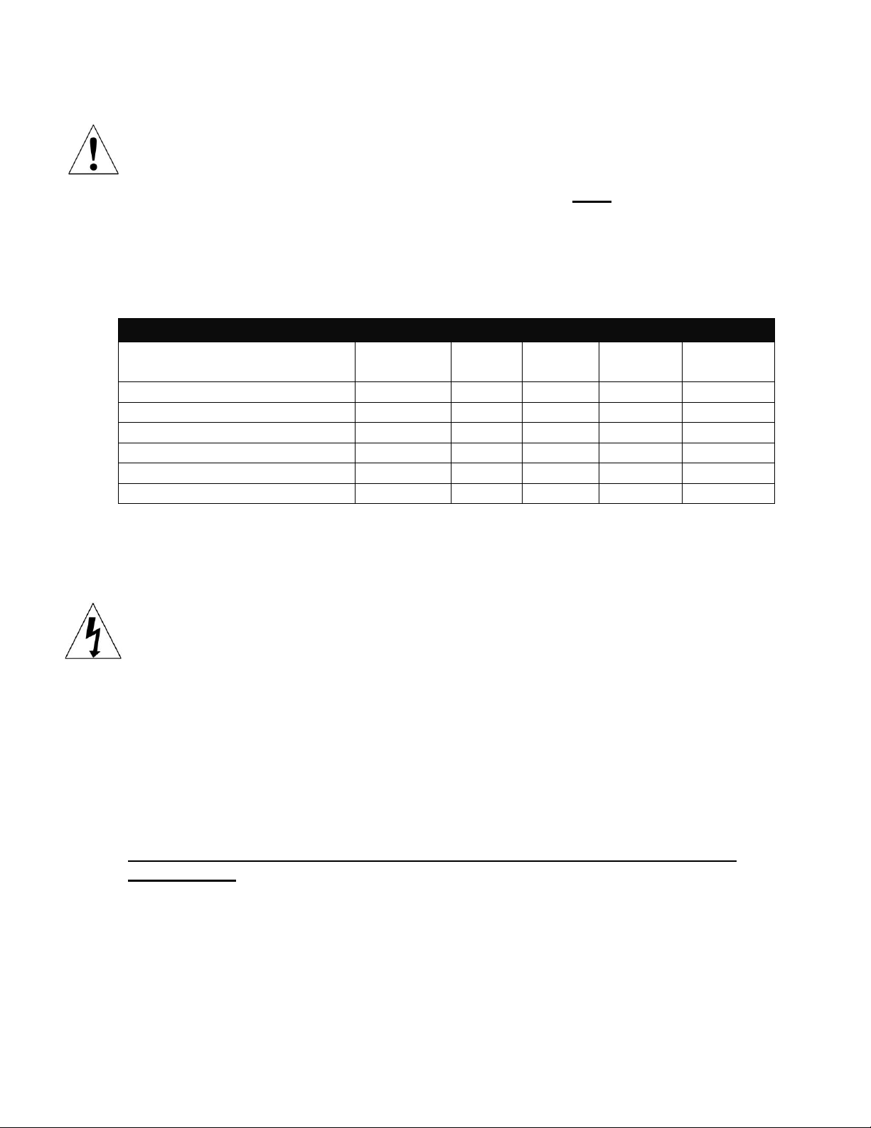
Preventive Maintenance for Your Tanning Booth
Recommended Care After Each
Session Weekly Monthly 6 Months Every
1000 hours
Clean goggles x
Inspect/clean vents x
Clean exterior of booth x
Inspect/clean reflectors x
Inspect/clean lamps x
Replace lamps x
Cleaning and Maintenance
Warning. Disconnect booth from electrical power before cleaning.
IT IS NECESSARY TO THOROUGHLY CLEAN AND SANITIZE YOUR ACRYLIC
AFTER EVERY USE TO ENSURE CAREFREE OPERATION AND TO MAXIMIZE
ITS TANNING EFFICIENCY. THE ACRYLIC SHOULD BE CLEANED WITH A
NON-ABRASIVE DISINFECTANT THAT DOES NOT CONTAIN AMMONIA A
ND/OR ALCOHOL. DO NOT USE COMMERCIAL CLEANERS SUCH AS
WINDEX OR 409.
USE OF AMMONIA AND/OR ALCOHOL ON YOUR BOOTH WILL VOID THE
WARRANTY!
When using Tanning Booth Cleaner, available at your Solar Storm Authorized Dealer, spray the
booth lightly, and wipe with a soft cloth.
When cleaning the tanning booth, use a cotton towel which is much less abrasive than a paper
towel. Never wipe with a dry cloth, as this will generate a slight static, which attracts dust.
Table of contents


