Solaria S6P2G User manual
www.solariaenergia.com
IEC Edition 3.0
v3-September-2012
Installation manual for Solaria photovoltaic
standard modules
S6M2G, S6P2G, S6M2G-3BB, S6P2G-3BB
2
www.solariaenergia.com
IEC Edition 3.0
v3-September-2012
Installation Manual
Tips for the Installer
Contents
-Safety Warnings
-Product Identification
-Fire Safety
-Unpacking And Transitory Use Of The Module
-Mechanical Installation
-Electrical Instructions
-Grounding
-Maintenance, Cleaning & Recycling
-Data Sheet (Electrical Performance)

3
www.solariaenergia.com
IEC Edition 3.0
v3-September-2012
Solaria Photovoltaic Modules
INSTALLATION, USE & MAINTENANCE
INSTRUCTIONS
This document contains information about the
installation and safety issues of the photovoltaic
modules manufactured by Solaria. Before handling
or connecting the modules it is very important to
read and understand all the instructions. The
module produces electricity as soon as the cells are
exposed to the sunlight. This manual is valid for the
following families of SOLARIA´s standard
photovoltaic modules: S6M2G and S6P2G.
DISCLAIMER
The manufacturer assumes NO liability for damage
incurred due to non-compliance of these
instructions. These instructions are only for
specialists who are familiar with the installation due
to their technical qualification.
PRODUCT CERTIFICATE & GUARANTEE
SOLARIA photovoltaic modules are manufactured
with high quality materials, according to the
international IEC 61215:2005 standards. The
modules are Class A rated according to the IEC
61730-1:2004 standards and they meet electrical
safety Class II requirements established in the IEC
61140 standard.
SAFETY WARNINGS
-Do not touch the electrical terminals when
the module is exposed to the light or while
the module is installed. The photovoltaic
modules produce electricity when they are
exposed to the light so the contact with the
conductor poles of the module can produce
sparks or burns.
-Cover the front side of the module with an
opaque element during the installation in
order to avoid the generation of electrical
current during the stages of mechanical and
electrical installation.
-Use only insulated tools that have the
necessary requirements to operate in
electrical installations
-DO NOT use modules near to
equipments or in places where inflammable
gases are accumulated.
-DO NOT handle the modules if they are
wet.
-Disconnect the module from other electrical
sources, as for example batteries during
installation or any other maintenance
activity. Read carefully manufacturer´s
instructions when using batteries.
-DO NOT touch the terminals with bare
hands.
-When working both in “rooftop and ground
mounted installations”, installers must wear
electrical safety boots.
-When assembling on the roof check existing
regulations and safety instructions to
prevent from falling objects and ensure you
follow accident prevention regulations and
use appropriate safety rails.
-Respect the polarity of the modules cables
at the interconnection with other modules
or another electric element.
-DO NOT disconnect the terminals while
the photovoltaic modules generate
electricity and are connected to the grid; in
this way you will avoid the risk of electrical
shock.
-Never dismantle the junction box, frame or
any other component of the module.
-When assembling and servicing photovoltaic
modules observe national grid regulations
and safety instructions for the installation of
electrical devices and any regulations from

4
www.solariaenergia.com
IEC Edition 3.0
v3-September-2012
the utility regarding the grid tie operation of
photovoltaic systems.
-When installing any product for lightning
and surge protection read carefully the
manufacturer´s specifications and national
grid regulations
Danger of Death!
-Before any operation of maintenance and
during installation, switch the modules off
with a disconnection switch. Working with
conductors which conduct direct current
can cause electric arcs.
-DO NOT exceed the maximum system
voltage specified in the label of the module
under any ambient temperatures.
Danger of Death!
-When connecting/disconnecting the
modules to the inverter take special care
and perform the operation under secure
conditions. Observe carefully the
instructions of the inverter. Even after
disconnection of the inverter there is a risk
of electric shock.
PRODUCT IDENTIFICATION
SOLARIA photovoltaic modules have a label at the
rear side that provides detailed information for the
identification of the product:
-The name of the module´s type is formed by
an “S”, followed by a number and a second
letter that determines the technology of the
cells. The word that identifies the family (for
example “2G”) is followed by a number that
shows the nominal power of the PV module
-The serial number, used to identify the
specific product. Every module has a unique
serial number.
-Electrical characteristics of the module.
-Maximum system voltage.
DO NOT remove the label.
If you remove the label, SOLARIA will not be responsible for the
warranty of the product.
FIRE SAFETY
-SOLARIA recommends checking local
authority guidelines and requirements for
building safety.
-DO NOT install modules near equipment or
locations where flammable gases can be
produced or located.
-When installing on a roof, modules must be
mounted on an approved fire resistant cover
for this type of installation.
-Operating temperature: All Solaria modules
must be mounted in environments that
ensure Solaria modules will operate within
the following maximum and minimum
operating temperature:
Maximum Operating
Temperature
+90º Celsius, +194º
Fahrenheit
Minimum Operating
Temperature
-40º Celsius-40
ºFahrenheit
UNPACKING & TRANSITORY USE OF THE MODULE
5
www.solariaenergia.com
IEC Edition 3.0
v3-September-2012
-Preserve the module in its package until it is
ready for installation.
-It´s recommendable to make all necessary
product inspection before installation.
-Do not use the junction box or external
connection wires to handle the module.
-Do not put the modules on the frame corners or
on top of each other. This could damage the
frames and shall lead the withdrawal of the
warranty of the module.
-It´s recommended opening the top and front
side of the packaging for the extraction of the
modules. Please do this operation carefully to do
not damage the glass or the backsheet.
-Do not store the modules on wet locations.
-Store modules with good ventilation and keep
contacts free of dust.
-Protect the glass and the backsheet of the
module against scratching or other damages.
MECHANICAL INSTALLATION
Site Selection
Select a suitable location to install the module. It
should be positioned avoiding any shadow from
other objects between 9.00 and 15.00h (during
the shortest day of the year). The photovoltaic
modules should typically face South in the
Northern Hemisphere and typically should face
North in the Southern Hemisphere. An ideal
installation should be with no shading effect at
any time during the year. Modules must be
correctly fixed in their place so they can resist
any load, including wind and the weight of the
snow.
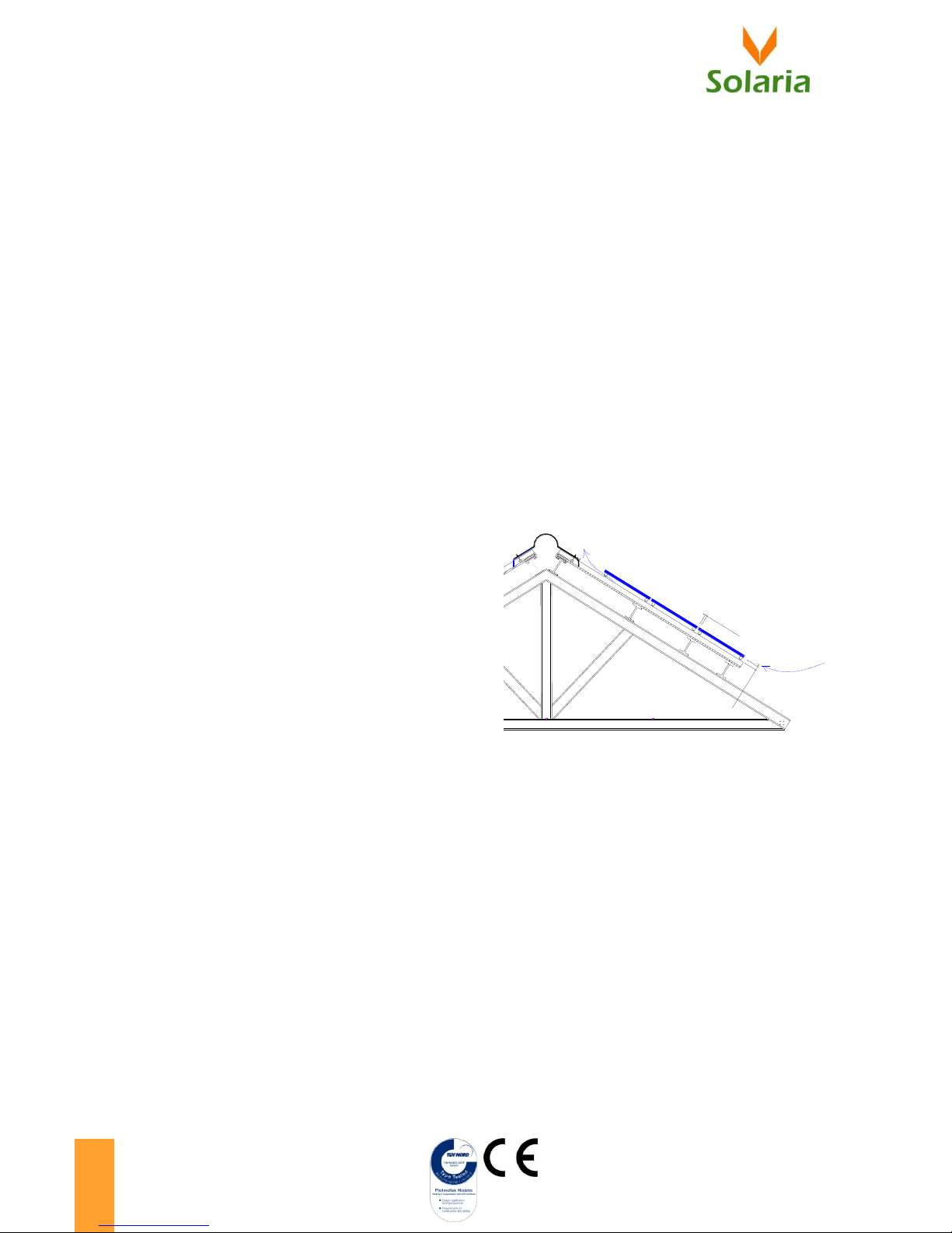
Ventilation
-It´s recommendable to install the modules
leaving a separation of 2 cm between them to
allow a correct thermal expansion.
-Assembling on roof allows good ventilation in
the back side of the modules assuring enough
distance between the back side and the
mounting structure. Minimum distance between
the wall or roof and the modules must be
approximately 10 centimetres to allow air
circulation behind the module and to dissipate
any condensation or moisture. Install the
modules in a way that air can flow between the
roof and the module.
Assembling
Manufacturer recommends attaching the modules
to the support structure using the proper fixing
systems according to the information provided in
this manual. The owner will be responsible of
damages caused by a wrong attachment.
Do not make drills in the frame or in the glass of
the module. Otherwise, SOLARIA will not be
responsible for the warranty of the product.
10cm
2cm
Linear Thermal Expansion
ventilation

6
www.solariaenergia.com
IEC Edition 3.0
v3-September-2012
Mechanical Load
-Modules must be properly fixed so they can
resist any load, including wind and snow load
specified in the product data sheet. The
attachments must be dimensioned to cope with
location´s load requirements.
Clamping System & Assembly boreholes
-Solaria PV modules can either be installed in a
vertical or horizontal position by using stainless
steel screws on the existing assembly boreholes
factory carved on the module frame or by using
module clamps on the module frame.
-If the module is installed in a horizontal position,
it must be fixed with a screw fitting or clamp on
the long side of the frame. DO NOT fix the
module using the short side of the frame.
-The minimum number of attachment points will
be 4as the number of the mounting frame holes
(see the detail of the drawing below) or 4
module clamps located in the right area (see
attachment guidelines).
Detail of one attachment point (mm)
Clamping System
Modules can be fixed to the structure by using fixing
module clamps. Module clamps must not deform
the frame and must not come in contact with the
front glass.
Assembly boreholes (with screw fitting)
Frame Holes: Secure the module to the structure by
using the mounting holes with a screw fitting. Four
0.25” or M6 stainless steel bolts, with nuts, washers,
and lock washer are recommended per module.
For other types of mounting methods, please consult SOLARIA.
Any different mounting methodology not checked first with
Solaria, will cancel the warranty of the product and the module
certification
Assembly
Boreholes
M6x12mm
Assembly
Module
Clamps
AssemblyBoreholes
M6X12mm
Assembly
ModuleClamps
Assembly
Boreholes
Assembly
Boreholes
AssemblyModule
Clamps
AssemblyModule
Clamps

7
www.solariaenergia.com
IEC Edition 3.0
v3-September-2012
Attachments Guideline
Maximum load 5.400 Pa
MODULE TYPE
VERTICAL ASSEMBLY
HORIZONTAL ASSEMBLY
S6P(S6M)2G
Screw fitting on assembly boreholes
L = 1646 mm / B = 991 mm
L1 = 1098 mm
L2 = 274 mm
Assembly with Module Clamps
Module Clamp
F = Distance to the module´s clamp axis
Fmin = 1/4 L
Fmax = 1/8 L
L = 1646 mm / B = 991 mm
L1 = 1098 mm
L2 = 274 mm
Clamps must be fixed on the longer side of
the frame
Screw fitting on assembly boreholes
L = 1646 mm / B = 991 mm
L1 = 1098 mm
L2 = 274 mm
Assembly with Module Clamps
Module Clamp
F = Distance to the module´s clamp axis
Fmin = 1/4 L
Fmax = 1/8 L
L = 1646 mm / B = 991 mm
L1 = 1098 mm
L2 = 274 mm
Clamps must be fixed on the longer side of the
frame
Assembly
Boreholes
M6x12mm
Assembly
Module
Clamps
AssemblyBoreholes
M6X12mm
Assembly
ModuleClamps
Assembly
Boreholes
Assembly
Boreholes
AssemblyModule
Clamps
AssemblyModule
Clamps
Assembly
Boreholes
M6x12mm
Assembly
Module
Clamps
AssemblyBoreholes
M6X12mm
Assembly
ModuleClamps
Assembly
Boreholes
Assembly
Boreholes
AssemblyModule
Clamps
AssemblyModule
Clamps
Assembly
Boreholes
M6x12mm
Assembly
Module
Clamps
AssemblyBoreholes
M6X12mm
Assembly
ModuleClamps
Assembly
Boreholes
Assembly
Boreholes
AssemblyModule
Clamps
AssemblyModule
Clamps
Assembly
Boreholes
M6x12mm
Assembly
Module
Clamps
AssemblyBoreholes
M6X12mm
Assembly
ModuleClamps
Assembly
Boreholes
Assembly
Boreholes
AssemblyModule
Clamps
AssemblyModule
Clamps

8
www.solariaenergia.com
IEC Edition 3.0
v3-September-2012
ELECTRICAL INSTRUCTIONS
-Photovoltaic stuffs should be installed by qualified
personnel only.
-In order to protect the module against hot spots,
the photovoltaic modules have protection diodes
(by-pass diodes) integrated in the junction box,
installed in the back side of the module.
-In normal conditions, SOLARIA modules can produce
more current and voltage than the indicated in the
standard conditions that appear in the module
label. For this reason, the Isc and Voc values should
be multiplied by a 1,25 factor for the design of the
fuses, wiring and other elements of the installation.
-Equipments and wiring should be suitable for
electrical photovoltaic systems. Use only UV-
resistant and weather-resistant elements. For the
wire section calculations the directive “2006/95/EC”
were used.
-The fuses amperage used to protect the system
from overcurrents is 15A. These fuses should be
placed in series with the module/s.
-Observe that electrical continuity exists between
the frames of the module because corner key used
between frames is Aluminium 6060 Treatment T6.
SOLARIA photovoltaic modules should be ground
connected for safety reasons.
Connecting modules in series
-Note that if modules are connected in series, the
total voltage will be equal to the sum of the
individual voltages, so modules connected in
parallel don’t make the system voltage to be higher
than the maximum system voltage specified in the
module label. All modules connected in series must
be modules of the same model.
-SOLARIA photovoltaic modules guarantee an
electrical isolation up to 1000 V. Consequently,
modules can be connected in series up to the
voltage mentioned above.
Connecting modules in parallel
-If the modules are connected in parallel, total
current will be the sum of all the individual currents,
which must be considered for the selection of the
type of connectors and the wire section
calculations.
Wiring and Junction Box
-DO NOT open the junction box.
-The junction box has an IP65 protection degree,
with fast no- error connectors with IP67
protection degree.
-Modules incorporate a solar cable with the
following specifications:
Size and type characteristics of the wires: 2 solar black
cables of 100 cm and a section of 4mm2with Tyco
Solar-Lock connectors. Plugs are marked with the
respective polarity. The Minus pole is minus-coded and
the Plus pole is neutrally coded:
Minus Pole Plus Pole
(Female Cable Coupler) (Male Cable Coupler)
Thermal Characteristics: Solar black cables must work
in a range of temperature between: - 40 ⁰ C and + 90 ⁰
C.

9
www.solariaenergia.com
IEC Edition 3.0
v3-September-2012
GROUNDING
-SOLARIA photovoltaic modules should be ground
connected for safety reasons. Modules have several
holes in the frame for this purpose, and wiring to
ground will be done using any of them. Please
follow instructions of grounding section. This
connection should be done according to the
standards and local regulations.
-SOLARIA recommends the following method for
grounding the module frame:
-Modules frame have two 0.16‘’
grounding holes that should be ground
connected for safety and protection
reasons.
-A stainless steel bolt M4 of 2 cm length
(Torque grading 1.08 Nm) will be used.
A nut M4 stainless steel will be used.
-It is suggested to use a single ground
conductor 12 AWG (General Cable
H07V-U).
-A spring stainless steel M4, 3 flats
washer stainless steel M4, a cup washer
M4, and a star washer stainless steel
M4, will be used to assembly the
grounding.
-SOLARIA also recommend the following methods for
grounding connection:
-Tyco Electronics Solklamp, M4 bolt
-Tyco Electronics Solklip, M4 bolt
MAINTENANCE, CLEANING & RECYCLING
-It’s recommended to wear rubber gloves for
electrical insulation whilst maintaining, washing
or cleaning modules.
-Do not walk or rest on the surface of the
module and do not drop anything on top of the
the module.
-SOLARIA photovoltaic modules do not need a
high level of maintenance, but it is advisable to
check their electrical and mechanical
connections periodically.
-When necessary, you can clean the surface of
the glass with water, a soft window cleaner (not
abrasive) and a cloth to avoid damages on the
surface.
-Non aggressive and abrasive cleaners or
chemicals should ever be used on the treated
Groundingholes
Drainageholes Drainageholes
Drainageholes Drainageholes
Orificiospara
PuestaaTierra
Orificiosde
Drenaje Orificiosde
Drenaje
Orificiosde
Drenaje Orificiosde
Drenaje

10
www.solariaenergia.com
IEC Edition 3.0
v3-September-2012
front glass. No alkali based chemicals should be
used including ammonia based solutions.
-SOLARIA suggest checking electrical connections
for loose connections and corrosion.
-In case of covering the surface of the module by
snow, DO NOT use any type of scraper. Perform
the operation with any other object than cutting
or stabbing.
-Frame is factory carved with special drains to
prevent accumulation of snow and rain on the
back side of the frame. DO NOT block or modify
these drain holes:
-To recycle the modules observe current national
requirements and consult a qualified and authorized
specialist.
Groundingholes
Drainageholes Drainageholes
Drainageholes Drainageholes
Orificiospara
PuestaaTierra
Orificiosde
Drenaje Orificiosde
Drenaje
Orificiosde
Drenaje Orificiosde
Drenaje
11
www.solariaenergia.com
IEC Edition 3.0
v3-September-2012
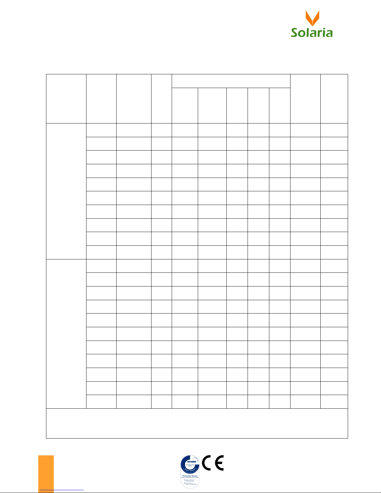
DATA SHEET
Module Series
Model
Dimensions
( ±3 mm )
Weight
(kg)
Electrical Performance @ STC (*)
Max.System
Voltage
[Vdc]
Max.Fuses
Series
[A]
Maximum
Power
Pmp [Wp]
Voltage at
Max.Power
Vmp [V]
Current
at
Max.
Power
Imp [A]
Open
Circuit
Voltage
Voc [V]
Short
Circuit
Current
Isc [A]
60 cells 156 x 156 mm
Monocrystalline Silicon
SPV Module
S6M2G195
1646x991x38
19
195
27,17
7,18
35,42
8,27
1000
15
S6M2G200
1646x991x38
19
200
27,52
7,27
35,66
8,29
1000
15
S6M2G205
1646x991x38
19
205
27,86
7,36
35,90
8,32
1000
15
S6M2G210
1646x991x38
19
210
28,20
7,45
36,14
8,34
1000
15
S6M2G215
1646x991x38
19
215
28,52
7,54
36,38
8,37
1000
15
S6M2G220
1646x991x38
19
220
28,84
7,63
36,62
8,39
1000
15
S6M2G225
1646x991x38
19
225
29,15
7,72
36,86
8,42
1000
15
S6M2G230
1646x991x38
19
230
29,46
7,81
37,10
8,44
1000
15
S6M2G235
1646x991x38
19
235
29,75
7,90
37,34
8,47
1000
15
S6M2G240
1646x991x38
19
240
30,05
7,99
37,58
8,49
1000
15
60 cells 156 x 156 mm
Polycrystalline Silicon
SPV Module
S6M2G245
1646x991x38
19
245
30,33
8,08
37,82
8,52
1000
15
S6P2G195
1646x991x38
19
195
27,90
6,99
35,14
7,80
1000
15
S6P2G200
1646x991x38
19
200
28,26
7,08
35,45
7,87
1000
15
S6P2G205
1646x991x38
19
205
28,60
7,17
35,76
7,95
1000
15
S6P2G210
1646x991x38
19
210
28,93
7,26
36,07
8,02
1000
15
S6P2G215
1646x991x38
19
215
29,26
7,35
36,38
8,10
1000
15
S6P2G220
1646x991x38
19
220
29,58
7,44
36,69
8,17
1000
15
S6P2G225
1646x991x38
19
225
29,89
7,53
37,00
8,25
1000
15
S6P2G230
1646x991x38
19
230
30,19
7,62
37,31
8,32
1000
15
S6P2G235
1646x991x38
19
235
30,49
7,71
37,62
8,40
1000
15
S6P2G240
1646x991x38
19
240
30,78
7,80
37,93
8,47
1000
15
(*) Electric values under Standard Test Conditions (STC) with an irradiation of 1000 W/m2, at an AM 1.5 solar spectrum and a
Temperature of 25⁰ C.
This manual suits for next models
3
Table of contents
Other Solaria Solar Panel manuals


-E6 Series installation manual")


