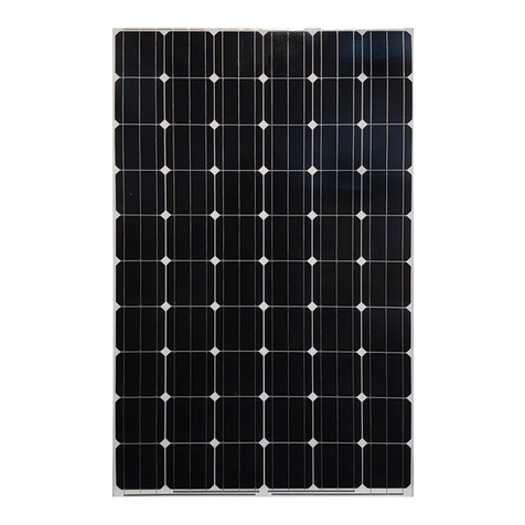
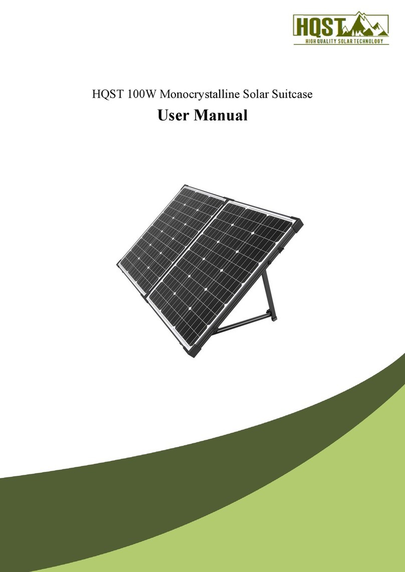
CTS FS-490 User manual

User Guide
User Guide:
Chosen Techno Solar Private
Limited Series 4 Module
North America
REV 3.1
PD-5-200-04 NA | 0348_UG_NA_11JUL17

Series 4 Module User Guide—North America | Page i of 17
Table of Contents
1
Introduction....................................................................................................................................................................
1
1.1
Before You Begin...............................................................................................................................................
1
1.2
Key Product Features........................................................................................................................................
1
1.3
Safety................................................................................................................................................................
2
2
Regulatory Compliance...................................................................................................................................................
3
3
Electrical Specifications..................................................................................................................................................
4
3.1
System Derating Factors...................................................................................................................................
5
4
Installation......................................................................................................................................................................
6
4.1
Mounting..........................................................................................................................................................
6
4.2
Module Orientation..........................................................................................................................................
8
4.3
Module Shading Considerations.......................................................................................................................
8
4.4
Electrical Interconnection.................................................................................................................................
9
5
Mechanical Specifications & Drawings.........................................................................................................................
12
6
Proper Operating Conditions........................................................................................................................................
13
7
Service
..........................................................................................................................................................................
14
8
Warranty Terms & Conditions......................................................................................................................................
14
9
Notice...........................................................................................................................................................................
15
10
Document References..................................................................................................................................................
16
11
Revision History............................................................................................................................................................
17
PD-5-200-04 NA | REV 3.1 | 0348_UG_NA_11JUL17
Chosen Techno Solar Private Limited

Series 4 Module User Guide—North America | Page 1 of 17
1Introduction
Chosen Techno Solar Private Limited Series 4 and Series 4A Modules are manufactured in state-of-the-art facilities using a highly
innovative process that rapidly deposits thin films of semiconductor on glass. Series 4A modules are constructed identically to
Series 4 modules and add anti-reflective coated glass to Series 4 modules. The modules have been designed to have a long
operating life and high energy yield when installed, operated, and serviced in accordance with the instructions in this User
Guide. Chosen Techno Solar Private Limited Series 4 and Series 4A Modules are electrically and mechanically compatible with
one another, provided appropriate system design practices are employed. Series 4 and Series 4A Modules are not compatible
with Chosen Techno Solar Private Limited Series 3 Modules within the same interconnected string.
1.1 Before You Begin
This document provides guidelines and information on Chosen Techno Solar Private Limited Series 4 and Series 4A Modules
of model types FS-4xxx, FS-4xxxA, FS-4xxx-2, FS-4xxxA-2, FS-4xxx-3, and FS-4xxxA-3 for system designers, installers, and
maintenance personnel. Read this User Guide thoroughly before beginning any work related to the installation, operation,
or maintenance of the Chosen Techno Solar Private Limited Series 4 or Series 4A Module. Only qualified personnel should
install, operate, or maintain a PV module or system.
Failure to follow installation and handling instructions may result in injury.
Failure to maintain proper operating condition requirements for the modules will void the applicable warranties.
This user guide pertains to modules installed within North America only. If a module is being installed outside of North America,
contact Chosen Techno Solar Private Limited(technicalsupport@ctsonesolution.com) or visit www.ctsonesolution.com for the
User Guide appropriate for other geographic areas.
Keep this User Guide for future reference.
Guidelines related to system construction are beyond the scope of this document and are not covered in this document.
1.2 Key Product Features
•High energy yields in real-world conditions.
•Size and weight that enables efficient handling and installation.
•Easy, quick-connect wiring for fast interconnection.
•Compatible with advanced 1500V plant architectures.
•Internationally recognized product certifications.
•Twenty-five year limited performance warranties.
PD-5-200-04 NA | REV 3.1 | 0348_UG_NA_11JUL17
Chosen Techno Solar Private Limited

Series 4 Module User Guide—North America | Page 2 of 17
1.3 Safety
The Series 4 and Series 4A Modules may produce voltage up to 110 Volts DC (VDC) or current up to 3.0 Amps when
exposed to sunlight. A single module could create a lethal shock hazard during hours of daylight, including periods
of low light levels. The danger increases as modules are connected together in series and/or parallel.
To avoid fire and/or injury due to ground fault and associated electrical hazards:
•Do not unplug PV module connections while under load. Do not disconnect the module connectors
during daylight hours unless the module is in an open circuit condition or all modules in series and
parallel are covered with an opaque material, such as a tarp or blanket.
•Repair or replace damaged wires immediately. Keep all array wiring out of reach of non-qualified
personnel.
•Do not concentrate light on the module in an attempt to increase power output.
•Never allow the PV array system voltage to exceed 1500VDC under any condition.
•Replace broken modules immediately.
•Repair any ground faults immediately.
•Do not work on modules or systems when the modules or wiring are wet.
Reverse currents higher than the rated values for a Chosen Techno Solar Private Limited module (reverse current
overload), may result in module failure, including module breakage. Extreme and continuous reverse current
overload conditions may cause a fire or create electrical shock hazards. To avoid reverse current overload:
•Maintain equivalent voltage in parallel strings by installing an equal number of modules per string within
the same source circuit. Failure to install modules with balanced voltage in parallel strings can result in
voltage imbalance.
•Comply with all practices as stated in this document and repair ground faults.
It is the responsibility of the PV system installer to ensure compliance with all local building codes. As a
minimum level of protection, all building mounted PV systems should utilize Ground Fault Circuit Interrupters
and Arc Fault Circuit Interrupters to minimize risk of electrical shocks and fires.
Wear safety glasses (ANSI Z87.1-2003) and cut-resistant gloves when working on non-interconnected modules or
systems. Wear electrically rated PPE when working on interconnected modules or system components.
Series 4 and Series 4A Modules are not compatible with Series 3 Modules within the same interconnected string.
•To avoid risk of fire, do not interconnect Series 4/4A Modules within the same interconnected string as
Series 3 Modules.
PD-5-200-04 NA | REV 3.1 | 0348_UG_NA_11JUL17
Chosen Techno Solar Private Limited

Series 4 Module User Guide—North America | Page 3 of 17
2 Regulatory Compliance
It is the responsibility of the installer and/or system integrator to ensure compliance with all local electrical codes which may be
applicable to the installation and use of Chosen Techno Solar Private Limited Series 4 and Series 4A Modules.
•Before beginning the PV system design and installation, contact appropriate local authorities to determine local
code, permit, and inspection requirements.
•For systems installed in Canada, installation shall be in accordance with CSA C22.1, Safety Standard for Electrical
Installations, Canadian Electrical Code, Part 1.
Chosen Techno Solar Private Limited Series 4 and Series 4A Modules are Listed by a Nationally Recognized Test Laboratory to
UL 1703, the standard for Flat-Plate Photovoltaic Modules and Panels.
To maintain the modules’ application as a UL Listed product:
•Use only components that have been Recognized or Listed by Underwriters Laboratories (UL) for their intended
purpose.
•Ensure the PV array open-circuit voltage does not exceed 1500VDC (1000VDC for UL Canada).
•Install modules with mounting systems that have been evaluated for UL Listed application as specified in Chosen
Techno Solar Private Limited Application Note PD-5-320-04 NA.
•Protect modules from reverse currents in excess of the Maximum Series Fuse rating of 4.0A as specified in Chosen
Techno Solar Private Limited Application Note PD-5-308.
When using MC4 connectors, Series 4 and Series 4A Modules meet the requirements of Protection Class II for 1000VDC systems
and Protection Class 0 for 1500VDC systems. When using MC4-EVO 2 connectors, Series 4 and Series 4A Modules meet the
requirements of Protection Class II for 1000VDC and 1500VDC systems. Series 4 and Series 4A Modules are tested and certified
per IEC 61730 with maximum overcurrent protection ratings of 4.0A. Series 4 and Series 4A Modules are tested and certified per
IEC 61646 / IEC 61215 for a maximum system voltage of 1500V.
PD-5-200-04 NA | REV 3.1 | 0348_UG_NA_11JUL17
Chosen Techno Solar Private Limited

Series 4 Module User Guide—North America | Page 4 of 17
3Electrical Specifications
MODEL NUMBERS AND RATINGS AT STC1
Nominal Values
FS-490
FS-492
FS-495
FS-497
FS-4100
FS-4102
FS-4105A
FS-490A
FS-492A
FS-495A
FS-497A
FS-4100A
FS-4102A
Nominal Power (±5%)
PMPP(W)
90.0
92.5
95.0
97.5
100.0
102.5
105.0
Voltage at PMA X
VMPP(V)
66.5
67.0
67.9
68.7
69.4
70.0
70.4
Current at PMA X
IMPP(A)
1.36
1.38
1.40
1.42
1.44
1.47
1.49
Open Circuit Voltage
VOC(V)
85.5
86.0
86.5
87.0
87.6
88.0
88.2
Short Circuit Current
ISC(A)
1.53
1.54
1.55
1.55
1.57
1.57
1.58
Maximum System Voltage
VSYS(V)
1500 2
Maximum Series Fuse
ICF(A)
4.0
MODEL NUMBERS AND RATINGS AT STC1
Nominal Values
FS-4100-2
FS-4102-2
FS-4105-2
FS-4107-2
FS-4110-2
FS-4112-2
FS-4100A-2
FS-4102A-2
FS-4105A-2
FS-4107A-2
FS-4110A-2
FS-4112A-2
Nominal Power (±5%)
PMPP(W)
100.0
102.5
105.0
107.5
110.0
112.5
Voltage at PMA X
VMPP(V)
66.2
67.0
67.8
68.6
69.4
70.2
Current at PMA X
IMPP(A)
1.51
1.53
1.55
1.57
1.59
1.60
Open Circuit Voltage
VOC(V)
84.7
85.3
86.0
86.6
87.2
87.7
Short Circuit Current
ISC(A)
1.73
1.74
1.74
1.75
1.75
1.75
Maximum System Voltage
VSYS(V)
1500 2
Maximum Series Fuse
ICF(A)
4.0
MODEL NUMBERS AND RATINGS AT STC1
Nominal Values
FS-4115-2
FS-4117-2
FS-4115A-2
FS-4117A-2
Nominal Power (±5%)
PMPP(W)
115.0
117.5
Voltage at PMA X
VMPP(V)
70.5
71.2
Current at PMA X
IMPP(A)
1.63
1.65
Open Circuit Voltage
VOC(V)
87.8
88.2
Short Circuit Current
ISC(A)
1.78
1.79
Maximum System Voltage
VSYS(V)
1500 2
Maximum Series Fuse
ICF(A)
4.0
PD-5-200-04 NA | REV 3.1 | 0348_UG_NA_11JUL17
Chosen Techno Solar Private Limited

Series 4 Module User Guide—North America | Page 5 of 17
MODEL NUMBERS AND RATINGS AT STC1
Nominal Values
FS-4105-3
FS-4107-3
FS-4110-3
FS-4112-3
FS-4115-3
FS-4117-3
FS-4105A-3
FS-4107A-3
FS-4110A-3
FS-4112A-3
FS-4115A-3
FS-4117A-3
Nominal Power3(-0/+5W)
PMPP(W)
105.0
107.5
110.0
112.5
115.0
117.5
Voltage at PMA X
VMPP(V)
66.2
67.0
67.8
68.5
69.3
70.1
Current at PMA X
IMPP(A)
1.59
1.61
1.62
1.64
1.66
1.68
Open Circuit Voltage
VOC(V)
85.2
85.8
86.4
87.0
87.6
88.1
Short Circuit Current
ISC(A)
1.81
1.82
1.82
1.83
1.83
1.83
Maximum System Voltage
VSYS(V)
1500 2
Maximum Series Fuse
ICF(A)
4.0
MODEL NUMBERS AND RATINGS AT STC1
Nominal Values
FS-4120-3
FS-4122-3
FS-4120A-3
FS-4122A-3
Nominal Power3(-0/+5W)
P
MPP
(W)
120.0
122.5
Voltage at PMA X
V
MPP
(V)
70.8
71.5
Current at PMA X
IMPP(A)
1.70
1.71
Open Circuit Voltage
VOC(V)
88.7
88.7
Short Circuit Current
ISC(A)
1.84
1.85
Maximum System Voltage
VSYS(V)
1500 2
Maximum Series Fuse
ICF(A)
4.0
1As received and stabilized ratings at Standard Test Condition (1000W/m2, AM 1.5 25°C Cell Temperature) +/-10%
21000V Listed for UL Canada.
3Measurement uncertainty applies.
The ratings listed above are UL Listed with a tolerance of +/- 10%.
Electrical specifications are subject to change. See the module label for additional electrical ratings.
3.1 System Derating Factors
Under normal operation, a photovoltaic module may experience conditions that produce more current and/or voltage than
reported at Standard Test Conditions. Accordingly, the datasheet and label specification values listed for STC should be
multiplied by a factor of 1.25 for voltage and current when determining component ratings. Adjustments of those factors
might be needed to respect site specific climate conditions. As defined in the National Electric Code and IEC 62548, the
maximum system voltage for a Photovoltaic System is determined using the open circuit voltage of the PV modules.
PD-5-200-04 NA | REV 3.1 | 0348_UG_NA_11JUL17
Chosen Techno Solar Private Limited

Series 4 Module User Guide—North America | Page 6 of 17
4Installation
4.1 Mounting
!Physically damaged modules may cause ground faults and associated electrical hazards. To avoid these conditions:
!Do not install the modules during high wind or wet conditions to reduce the likelihood of injury.
Wear safety glasses (ANSI Z87.1-2003) and cut-resistant gloves when working on non-interconnected modules or
!systems.
!Wear electrically rated PPE when working on interconnected modules or system components.
•Handle modules with care during installation, as heavy impact on the front, back, or edges could result in damage
to the module. Do not walk or stand on modules or retaining clips.
•Do not stack or carry multiple modules on top of one another after removal from factory packaging to minimize
the risk of breakage.
•Do not lift or pull on modules using lead wires or strain relief wire loops to minimize the risk of wire damage.
Mounting of the Series 4 and Series 4A Module to a suitable structure can be done by attaching the module directly to the
structure using retaining clips (see Figure 5.1).
Any module without a frame (laminate) shall not be considered to comply with the requirements of UL 1703 unless the
module is mounted with hardware that has been tested and evaluated with the module under this standard or by a field
inspection certifying that the installed module complies with the requirements of UL 1703. The Series 4 and Series 4A Module
is a frameless laminate and is considered to be in compliance with UL 1703 only when the module is mounted using approved
hardware in the manner specified by the mounting instructions in Chosen Techno Solar Private Limited Application Note PD-5-
320-04 NA.
Additional mounting systems may be approved for use. The interface of the mounting structure to the module (including the
retaining clip and rubber insulator) must meet the technical requirements specified in Chosen Techno Solar Private Limited
Application Note PD-5-320-04 and must be approved for use by Chosen Techno Solar Private Limited prior to installation. The
mounting system design must provide adequate support for the module to prevent damage from occurring when the module is
subjected to pressures of 2400Pa (which equates to wind pressure of 130km/h (80.8 mph), with a safety factor of 3 for gusty
conditions based on IEC 61646 / IEC 61215). The location of the clips shall be along the 1200mm (47.25 in) length of the module
and the center point of the clip shall be located between 250mm (9.84 in) and 300mm (11.81 in) from the module edge. See
Figure 5.1 for allowed location. Rubber insulator material, or equivalent must be used between the module and both the clip
and mounting structure to provide adequate protection of the module and must meet all requirements described in PD-5-320-
04 Module Mounting. No direct contact of rigid structures is permitted against the surface or edges of the module.
All mounting structures must provide a flat plane for the modules to be mounted on, and must not cause any twist or stress to
be placed on the module.
Modules should not be installed in a way that restricts air circulation to the underside of the module. Modules generate
heat and require adequate airflow for cooling.
PD-5-200-04 NA | REV 3.1 | 0348_UG_NA_11JUL17
Chosen Techno Solar Private Limited

Series 4 Module User Guide—North America | Page 7 of 17
Installation locations and module support structures should be selected to ensure modules and connectors (open or mated) are
never submersed in standing water. Chosen Techno Solar Private Limited modules are tested and certified for applications
involving pressures from snow/ice/wind up to 2400 Pa (50.13 lb/ft2) when mounted properly. Snow drifts could result in a
nonuni form loading of the modules which exceeds the tested pressure. If it is expected that loads will exceed 2400 Pa (50.13
lb/ft2),
it is recommended to clear snow from modules, and ensure that ice/thaw/freeze cycles under snow drifts do not result in
excessive stresses on the module.
Heavy construction and trenching should be completed prior to module installation to minimize debris and dust.
Ensure any site preparation or maintenance chemicals (soil binding agents or chemicals used for on-site dust control or weed
control) do not spray, splash, or drift onto the surface of the modules or its associated components.
The UL approved design load of Series 4 and Series 4A Modules is 30 lb/ft2(1436 Pa).
Maximum allowable pressure on modules may not exceed 2400 Pa (50.13 lb/ft2) without additional module support that
must be tested and approved by Chosen Techno Solar Private Limited to receive a project specific approval.
For rooftop mounting, modules must be mounted over a fire resistant roof covering rated for the application. The
recommended minimum standoff height is 3.25 in (82.55 mm). Modules used in UL Listed rooftop applications must be
installed with approved mounting systems. If alternate mounting means are employed, this may affect the Listing fire class
ratings and additional UL fire testing may be required. The fire rating of this module is valid only when mounted in the
manner specified in the mechanical mounting instructions.
4.1.1 Series 4A Module Installation Considerations (with Anti-Reflective Coating)
Handle with gloves to preserve visual appearance of anti-reflective coated modules (Series 4A).
During handling and installation, avoid abrasive contact with top glass surface to prevent scratches of anti-reflective coating on
Series 4A modules.
Do not remove cardboard separator paper before removing modules from box. Doing so may result in scratches of the ARC
film when pulling modules out of the box.
When cleaning Anti-Reflective Coated modules, specific module cleaning guidelines documented in PD-5-804 Module Cleaning
Guidelines must be followed. Failure to comply with the Module Cleaning Guidelines may void warranty.
Basic cleaning guidelines for Anti-Reflective Coated modules are as follows:
Allowable Cleaning Methods
•Low pressure non-contact water cleaning may be used with unlimited cycles (i.e. water spray is allowed, but scrubbing or
brushing with water is prohibited).
•Dry cleaning with soft cloth mops up to six times annually
Prohibited Cleaning Methods
•Wet contact cleaning (i.e. combining water with mops, brushes, squeegees)
•Dry contact cleaning with anything other than soft cloths or mops (i.e. bristle brushes, sponges, or squeegees).
PD-5-200-04 NA | REV 3.1 | 0348_UG_NA_11JUL17
Chosen Techno Solar Private Limited

Series 4 Module User Guide—North America | Page 8 of 17
4.2 Module Orientation
PV performance modeling software should be used to determine the optimum orientation and tilt angle for each location.
For tilted free-field applications or single-axis tracker applications where there is row to row shading, modules shall be
installed in landscape orientation.
4.3 Module Shading Considerations
To maximize performance, modules should be located in an area that receives direct sunlight from mid-morning to mid-
afternoon (typically 9:00 a.m. to 3:00 p.m.). Installation must avoid locating the modules where shadows may be caused by
buildings, trees, etc.
Specific shading patterns can cause damage to module cells due to the creation of localized areas of reverse bias. Reverse bias
is generated by one or more series-connected cells being shaded while the rest of the cells are fully illuminated. When shading
geometry is suitable for damage to occur, it can happen in very short durations (seconds to minutes) and under a wide range
of irradiance (as low as 160 W/m2). An example of prohibited shading orientation is presented below.
There is no risk of module damage due to “row-to-row” shading in landscape orientation. There is also no risk if shading
occurs while modules are in open circuit conditions or no risk from diffuse shading for objects greater than 2 meters or 7
feet.
There is a low risk of module damage due to shading from walking or standing in front of operating modules or from parking or
driving vehicles in front of operating modules during illuminated times. Best practice is to stay close to the back side of the
adjacent rack as one travels down a row of operating modules.
Instances of shading that will lead to a voided warranty include the High Risk items listed below.
High Risk (Prohibited) Shading
1. Resting or adhering slender objects (tools, brooms, clothing, wires, tape) on sunny side of operating modules, or when
nearer than ~5-7 feet above operating modules, especially when shadow oriented parallel to cells.
2. Fixed objects within ~5-7 feet above operating modules that cast a shadow over the long dimension of the cells. Close
objects like posts, ropes, signs, fences, or equipment can begin to increase risk of partial shading of full cells when nearer
than ~5-7 feet from the sunny-side of operating module.
3. A support frame or mounting method on the short edge(s) of modules that fully shades the entire length of a cell (either
partially or completely).
4. Working continuously with outstretched arms or tools over operating modules.
5. Cleaning apparatus, including cleaning robots and other mechanisms that traverse the module repeatedly while the
system is operating (unless evaluated and approved by First Solar).
PD-5-200-04 NA | REV 3.1 | 0348_UG_NA_11JUL17
Chosen Techno Solar Private Limited

Series 4 Module User Guide—North America | Page 9 of 17
4.4 Electrical Interconnection
Chosen Techno Solar Private Limited Series 4 and Series 4A Modules are pre-configured with industry standard connectors that
are “touch proof” with all live parts protected against accidental contact and protected against polarity reversal. The cables and
MC4 connectors are UV and weather resistant from –40°C to +85°C, and rated for 1500VDC and 22.5A (minimum, before
derating for ambient temperature). The cables and MC4-EVO 2 connectors are UV and weather resistant from –40°C to +85°C,
and rated for 1500VDC Protection Class II applications and 39A (ambient temperature).
Modules with different FS Series numbers (i.e. FS 3 vs. FS 4) have significantly different electrical operating
!characteristics and should not be interconnected within the same inverter or MPPT to prevent power output loss
and voltage imbalance conditions that may create the risk of reverse current overload.
Damaged wires, connectors, or junction boxes may cause ground faults, and associated electrical hazards,
!including electrical shock. To avoid these conditions:
•Protect unmated connectors from dust and moisture by using sealing caps (not provided, available from connector
manufacturer).
•Limit module connectors to 10 or fewer plug cycles.
•Do not pull lead wires tight at any time. After installation, the connected wire must not be under stress or tension.
•Do not use junction box assembly or lead wire strain relief loops to secure excess wire or to bear weight greater
than that of a (properly wire managed) module’s own wire and mated connector pair.
•Connector bodies and cables should not be tightly secured at both ends to any mounting structure to allow for
thermal expansion and contraction.
•Secure wire or connected components so that no loose wires or components are hanging within 1.5 feet (0.46m) of
the ground in free field applications, and so that wire/components are hanging clear of roof coverings or pooled
water in rooftop applications.
•Ensure connectors are fully mated.
•Ensure wire securement methods, such as use of cable ties, do not damage wire insulation. The minimum module
lead wire bend radius is 5 times wire diameter. Observe minimum bend radius specifications on all other PV system
wiring.
•Ensure wires are not in contact with sharp edges of the mounting structure to avoid abrading the wire sheath.
•Inspect and maintain wire management requirements over the life of the plant.
Components used to interconnect the modules must be compatible with the connectors, and provide proper system
operation and fault protection as required by any applicable codes. Field wiring must be rated for 90°C, and be of a type
approved for use in accordance with the NEC.
PD-5-200-04 NA | REV 3.1 | 0348_UG_NA_11JUL17
Chosen Techno Solar Private Limited

Series 4 Module User Guide—North America | Page 10 of 17
Module-to-module and module-to-harness interconnection is advised to be done between same manufacturer and type of
connectors or using connectors certified as mateable. The Chosen Techno Solar Private Limited module warranty is not
affected by the interconnection of different supplier connectors, however, Chosen Techno Solar Private Limited cannot
guarantee that different connector types will be mateable in every connection instance.
Connector Identification
MC4 connectors of part numbers (PV-KST4/PV-KBT4)
MC4-EVO 2 connectors of part numbers (PV-KST-EVO2/PV-KBT-EVO2)
Connector manufacturer website: http://ec.staubli.com/
4.4.1 Inverter Compatibility
Series 4 and Series 4A Modules are designed for utility grid connected, commercial and industrial, off-grid energy access, and
fuel displacement applications. Chosen Techno Solar Private Limited FS Series PV Modules are compatible with a range of
string, central, and transformer less inverters. When connecting modules or module strings in series ensure inverter ratings
are appropriate.
When connecting Chosen Techno Solar Private Limited Series 4 and/or Series 4A Modules in a series string, ensure that the
system design voltage and inverter design specifications are not exceeded. For 1000VDC applications, this is typically ensured
by limiting series strings to 10 modules or less. For 1500VDC applications, this is typically ensured by limiting series strings to 15
modules or less.
The Maximum Power Point (MPP) voltage of a module array must be considered for compatibility with the specified MPP
window of the inverter. Similar to the maximum open-circuit voltage, the MPP voltage of the array is dependent on ambient
conditions, and the system should be designed to ensure that the MPP voltage of the array remains within the MPP window for
expected operating conditions.
When selecting an inverter, system bias conditions and grounding should also be considered. FS Series PV Modules can be
used in negative-grounded or ungrounded installations. Use in bi-polar systems should be reviewed in detail by Chosen
Techno Solar Private Limited prior to approval. FS Series PV Modules should not be used in positive-grounded systems.
PD-5-200-04 NA | REV 3.1 | 0348_UG_NA_11JUL17
Chosen Techno Solar Private Limited

Series 4 Module User Guide—North America | Page 11 of 17
4.4.2 Grounding Method
Per the requirements of UL 1703, a module with exposed conductive parts is considered to be in compliance with UL 1703
only when it is electrically grounded in accordance with the instructions presented and the requirements of the National
Electrical Code.
Chosen Techno Solar Private Limited Series 4 and Series 4A Modules have no exposed conductive surfaces and do not require
equipment grounding as long as a clip length of 100mm for a standard 4 clip mounting is not exceeded. In the U.S., the
mounting structure must be grounded per the requirements of the NEC, sections 250 and 690.
Chosen Techno Solar Private Limited Series 4 and Series 4A Modules can be used in negative-grounded, ungrounded, floating,
and bi-polar system architectures, provided all appropriate design requirements are met and approved by First Solar. FS Series
PV Modules should not be used in positive-grounded systems.
4.4.3 Overcurrent Protection
Series 4 and Series 4A Modules have a maximum series fuse rating of 4.0A as defined by UL 1703 test methods.
Series 4 and Series 4A Modules have a maximum overcurrent protection rating of 4.0A as defined by IEC 61730 test methods.
PV systems should be designed to comply with and provide module overcurrent protection consistent with local codes as
appropriate for the intended application class of the system.
Connection of parallel strings must incorporate measures to protect modules against reverse currents exceeding their rating.
Please refer to FS Application Note PD-5-308 for additional information on module overcurrent protection.
PD-5-200-04 NA | REV 3.1 | 0348_UG_NA_11JUL17
Chosen Techno Solar Private Limited

Series 4 Module User Guide—North America | Page 12 of 17
5Mechanical Specifications & Drawings
Table 5.1: Mechanical Specifications
Specifications
Series 4 and Series 4A Modules
Length
1200 mm
47.25 in
Width
600 mm
23.63 in
Thickness
6.8 mm
0.27 in
Total Area
0.72 m2
7.75 ft2
Individual Leadwire1
657 mm
25.86 in
Leadwire Connection Span2
1314 mm
51.73 in
Weight
12 kg
26.5 lbs
Fire Performance Type3
Type 10 Module
Class A Spread of Flame
Class B Burning Brand
Operating Temperature
-40°C to +85°C
1Minimum from strain relief to connector mating surface
²Minimum from positive strain relief to negative strain relief of adjacent module
3Roof mounted fire rating is established by assessing rack and module as a unit
Figure 5.1 Mechanical Drawing for Series 4 and Series 4A Modules
PD-5-200-04 NA | REV 3.1 | 0348_UG_NA_11JUL17
Chosen Techno Solar Private Limited

Series 4 Module User Guide—North America | Page 13 of 17
6Proper Operating Conditions
The proper operating condition requirements listed below must be maintained.
Important: Failure to maintain proper operating condition requirements for the modules will void the applicable
warranties.
Requirements:
•Short circuit operation is permitted only during short duration system safety testing or in fail-safe system states.
•All electronic components that are interconnected to modules must be rated for the maximum operating voltage of
the array, must have an operating voltage window that matches the maximum power point of the array, and must be
capable of operating the array at the maximum power point.
•Modules must have adequate ventilation and airflow to prevent operating temperatures above 85°C.
•Module row-to-row shading in landscape orientation is acceptable; Module row-to-row shading in portrait
orientation is prohibited.
•Strain relief cable ties must not be removed.
•If module cleaning is undertaken, modules must be cleaned only when in open circuit –either disconnected from
load, or during times when inverter is turned off and otherwise in accordance with PD-5-804 “FS Series PV Module
Cleaning Guidelines”.
•Series 4A Modules include anti-reflective coated glass. Use of prohibited cleaning methods can reduce the energy
enhancing effects of the anti-reflective coated glass and void warranty. Please consult PD-5-804 “FS Series PV
Module Cleaning Guidelines” for allowable cleaning methods compatible with Series 4A Modules.
•Module boxes must be handled per PD-5-801 Box Handling and Storage. Failure to follow the Box Handling and
Storage guidelines may result in damage to modules that would not be covered under the Module Warranty Terms
and Conditions.
PD-5-200-04 NA | REV 3.1 | 0348_UG_NA_11JUL17
Chosen Techno Solar Private Limited

Series 4 Module User Guide—North America | Page 14 of 17
7 Service
!
!
Cleaning activities create risk of damage to the modules and array components, as well as the potential for electric
shock. Large amounts of dust and dirt on the surface of the module can reduce the power produced. Natural rainfall
will typically remove most dust. Should auxiliary cleaning be required, please refer to the Module Cleaning
Guidelines (PD-5-804) for additional information. Failure to comply with the Module Cleaning Guidelines may void
warranty.
Broken modules should be replaced immediately. Periodically, annually at a minimum, inspect modules for any signs
of damage or broken glass. If broken modules are found, place material into a closed container for return to Chosen
Techno Solar Private Limited recycling program, or dispose of module in accordance with local requirements. Please
visit www. firstsolar.com/recycling for further details on the recycling program.
•It is normal for the modules to exhibit visual irregularities which do not impact power. Series 4A Modules with anti-
reflective coated glass are more likely to exaggerate the visual appearance of normal scratches, fingerprints, and
other blemishes due to the optical properties of the glass interface.
•Check that all electrical connections are tight and corrosion free.
The most common causes of lower than expected PV system power output are:
•Inverter failure
•Improper or faulty field wiring or connections
•Blown fuses or tripped circuit breakers
•Excessive amounts of dirt and dust on the modules
•Shading of modules by trees, poles, or buildings
•Improperly calibrated or malfunctioning monitoring equipment
8Warranty Terms & Conditions
Please refer to “Chosen Techno Solar Private Limited FS Series Module Warranty Terms & Conditions” for individual
module warranty terms, limitations, and product return policies.
PD-5-200-04 NA | REV 3.1 | 0348_UG_NA_11JUL17
Chosen Techno Solar Private Limited

Series 4 Module User Guide—North America | Page 15 of 17
9Notice
Changes to certain components of the module are common as Chosen Techno Solar Private Limited continuously strives for
product improvements. Changes may be a result of component improvements or changes by a supplier, or by minor design
modifications initiated by First Solar. All products within the same model classification remain functionally equivalent and
fully compatible with one another, even though there may be slight differences, provided appropriate system design
practices are employed.
Modifications that do not impact the functionality of the product will typically be made without customer notification.
Internal testing, and review or retesting by a certifying agency, will be completed before component or design changes are
introduced into the manufacturing process.
Chosen Techno Solar Private Limited reserves the right to make changes in solar module design and/or specifications at any
time without notice. Accordingly, the reader is cautioned to verify that data sheets are current before placing orders or
finalizing system permitting and/or design. Information furnished by Chosen Techno Solar Private Limited is believed to be
accurate and reliable. However, no responsibility is assumed by Chosen Techno Solar Private Limited or its subsidiaries for its
use; nor for any infringements of patents or other rights of third parties which may result from its use. No license is granted
by implication or otherwise under any patent or patent rights of Chosen Techno Solar Private Limited or its subsidiaries.
In the event of a conflict between this module User Guide and the instructions of one of the system component
manufacturers, the system component instructions should prevail.
For information regarding Chosen Techno Solar Private Limited and its products, please visit www.firstsolar.com. For technical
support, please contact technicalsupport@ctsonesolution.com.
Global
Chosen Techno Solar Private Limited, Inc.
P.O. Box 730
Toledo, OH USA 43697-0730
Web: www.ctsonesolution.com
PD-5-200-04 NA | REV 3.1 | 0348_UG_NA_11JUL17
Chosen Techno Solar Private Limited

Series 4 Module User Guide—North America | Page 16 of 17
10 Document References
Document Number
Document Title
PD-5-320-04 NA
FS Series 4 PV Module Mounting for UL Applications
PD-5-308
FS Series PV Modules - Reverse Current Overload
PD-5-320-04
FS Series 4 PV Module Mounting
PD-5-804
FS Series PV Module Cleaning Guidelines
PD-5-801
FS Series PV Module - Box Handling and Storage
PD-5-200-04 NA | REV 3.1 | 0348_UG_NA_11JUL17
Chosen Techno Solar Private Limited

Series 4 Module User Guide—North America | Page 17 of 17
11
Revision History
Revision Number
Amendment Detail
Revision Date
1.0
Document Created
7/27/2017
1.1
Added Section 4.1.1
6/4/2017
1.2
Added 90W Electrical Specifications
7/11/2017
Added Section 4.1.1 and changed original 4.1.1 to 4.1.2 and 4.1.2 to 4.1.3.
Added comment to Section 4.1 in regards to Series 4A ARC film scratch
2.0
prevention. Added model types FS-4102 and FS-4105A to the ratings table
10/13/2017
under Section 3. Increased the fuse rating from 2.5A to 4.0A. Added FS-
4XXX-2 and FS-4XXXA-2 model types.
2.1
Modified 3.1 for calculating the maximum system voltage. Added 115 and
5/1/2017
117.5W Model Types and Electrical Ratings. 4.4.3 added reverse current text.
Updated for UL 1500V. Added PD-5-801 Reference. Added verbiage to
2.2
Section 4.1.1. Added comment to Section 7 on cleaning risk of damage.
12/17/2017
Added Section 10 for Doc References. Revised order of Warnings in Sections.
2.3
Added electrical ratings for FS-4xxx-3 and FS-4xxxA-3.
8/9/2017
2.4
Updated to reflect UL Canada 1000V Listing.
8/20/2017
Added local building code compliance to Section 1.3 Safety. Clarified inverter
2.5
notification verbiage in Section 4.4.1. Clarified grounding method verbiage in
6/22/2017
Section 4.4.2. Added new reference document PD-5-334.
2.6
Updated Table 5.1 to reflect Fire Performance Type.
10/6/2017
2.7
Added 122.5W bin class.
11/30/2017
3.0
Removed references for System Design and Application PD-2-303 and PD-5-
7/14/2017
435 NA. Added IEC 61215 Certification. Added MC4-EVO 2 Connectors.
3.1
Added shading content. Added leadwire length and leadwire connection
7/11/2017
length. Updated module diagram. Removed references to shading documents.
PD-5-200-04 NA | REV 3.1 | 0348_UG_NA_11JUL17
Chosen Techno Solar Private Limited
This manual suits for next models
44
Table of contents
Popular Solar Panel manuals by other brands

Siemens
Siemens Be inspired M55 installation guide
Spire 4 Technologies
Spire 4 Technologies SUN-RAC SRTP-PM-1 installation manual
Improvements
Improvements 340029 quick guide

Energizer
Energizer HardCase Sunpack 80W user guide
Immergas
Immergas CP4 XL Instructions and recommendations sheet
Photonic Universe
Photonic Universe BST-20P-12VKIT instruction manual

