SOLATHERM PV360SWT Switched User manual

Power Control Equipment
PV DC Electric Hot Water
Product Manual
1/52 Barnett Ave, Glynde SA 5070
Phone (08) 8337 8881
www.solatherm.com.au
Model:
PV360SWTSwitched
PV360BMS Shared
Heating with Secondary Output
Power Control Equipment (PCE)

1 | P a g e
ATTENTION
The Solatherm controller and water heater vessel must be installed by an
authorised person and the installation must comply with all the relevant Australian
Standards, local and industry regulations.
ATTENTION
This appliance is not intended for use by persons (including children) with reduced
physical, sensory or mental capabilities, or lack of experience and knowledge, unless
they have been given supervision or instruction concerning use of the appliance by a
person responsible for their safety.
Children should be supervised to ensure that they do not play with the appliance
WARNING
Once installed the hot water tank is powered by TWO SOURCES of Power Supply,
both sources must be isolated before working on the appliance.
Before commencement of any service work on the hot water circuit,
including work that partially or completely drains the storage vessel,
ensure all electrical supplies, the Photovoltaic array and AC connection
have been disconnected as per the System Shutdown procedure in this
manual.
PV ARRAY WARNING
When the photovoltaic array is exposed to light, it supplies a d.c. voltage to the PCE.
WARNING
The controller is only to be connected to a hot water cylinder specifically designed
and configured for use with the Solatherm DC controller (P.C.E.). It is not for retrofit.
WARNING
If the equipment is used in a manner not specified by the manufacturer, the
protection provided by the equipment may be impaired.
CONNECTION WARNING
Solatherm Photo Voltaic Over Temperature Cut Out (PVOTC) must be installed in
the power supply feed to the DC heating element.
WARNING
DANGER the operation of the PV (DC) thermal cut out indicates a possibly
dangerous situation. The water heater must be inspected by a qualified person and
the PV-OTC (PV thermal cut out) replaced.

2 | P a g e
WARNING
DANGER the operation of the 240V AC thermal cut out indicates a possibly
dangerous situation. Do not reset the 240V AC thermal cut out until the water
heater has been serviced by a qualified person.
PV ARRAY WARNING
Maximum array power of 3.84kW must not be exceeded. Current must not exceed
22 Amps, array design must not exceed 2 strings. Voltage must not exceed 270V,
String length must not exceed 6 panels.
Max power must not be exceeded.
3.84kW can be either 270V @14.2A or 174V @ 22.0A or in between.
P=IR (Volts x Current), 3840W must not be exceeded.
WARNING
The controller has no user serviceable parts. Opening the cover will void all
warranty and may expose dangerous voltages.
Removal of the covers on the storage water vessel will expose live electrical wiring.
Covers must only be removed by an authorised service person and only once dual
supply power has been isolated.
ATTENTION
Ensure all glands from the control box are firmly tightened to ensure ingress
protection.
ELECTRICAL WARNING
All electrical work and permanent wiring must be carried out by a qualified person
and in accordance with all current relevant Australian installation standards and
local authority requirements.
Means for disconnection must be incorporated in the fixed wiring in accordance
with the wiring rules.
All electrical connections must be terminated before switching any component on.
The power to the Solatherm solar control unit and water heater must NOT be
switched on until the water heater is completely filled with water and all air bled
from the system.
3 | P a g e
WATER CONNECTIONS FOR STORAGE VESSEL
Please ensure all plumbing installation work is carried out in accordance with
AS3500 and that a non-return valve is installed in the incoming water line.
Maximum inlet pressure 700kPa, minimum inlet pressure 350 kPa.
A pressure relief valve must be fitted in accordance with AS 3500, rating 850kPa
10kW. A discharge pipe must be connected to the device and be installed in a
continuously downward direction and in a frost-free environment and the end must
be left open to atmosphere.
DANGER
Failure to operate the relief valve easing gear at least once every six months may
result in the water heater exploding. Water may drip from the discharge pipe but
continuous leakage from the valve may indicate a problem with the water heater,
please have your water heater serviced by a qualified person.
If the water supply pressure exceeds the rated pressure, a pressure reducing valve is
to be fitted in the installation.
The water may drip from the discharge pipe of the pressure-relief device and that
this pipe must be left open to the atmosphere;
The pressure-relief device is to be operated regularly to remove lime deposits and
to verify that it is not blocked;
The water heater can be drained by disconnecting the water inlet.
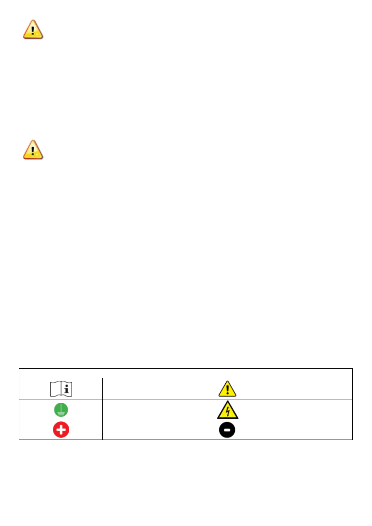
Symbol Glossary
Symbols Used
Refer to the operating
instructions
Caution, risk of danger
Protective conductor
terminal
Caution, risk of electric
shock
Positive conductor
Negative conductor

4 | P a g e
Contents
Symbol Glossary ..............................................................................................................................................3
Contents ..........................................................................................................................................................4
About ...............................................................................................................................................................5
Display .............................................................................................................................................................6
Basic System Configuration .............................................................................................................................7
Start-up Procedure.................................................................................................................................8
System Shutdown...................................................................................................................................8
Frequently Asked Questions............................................................................................................................9
Troubleshooting ............................................................................................................................................11
Installation Instructions.................................................................................................................................12
Wiring Diagram - Controller......................................................................................................................12
On the Ground ..........................................................................................................................................13
Wall mounting PCE controller..............................................................................................................13
Mounting Clearances and Mount Point Locations ..............................................................................14
Connection: Controller to Storage Water Vessel.................................................................................15
Wiring Diagram - PVOTC - Element......................................................................................................16
Connection - Main Array Input ............................................................................................................17
Connection - Secondary Output...........................................................................................................18
Connection - Boost Element - AC.........................................................................................................19
ON THE ROOF ................................................................................................................................................20
Panel Configuration..............................................................................................................................20
Commissioning Start Up ................................................................................................................................21
Shut down Procedure...........................................................................................................................21
Warranty........................................................................................................................................................22
Warranty Definitions ................................................................................................................................22
Warranty Conditions.................................................................................................................................22
Warranty Exclusions .................................................................................................................................23
Commissioning ..............................................................................................................................................24
System Information - Form A....................................................................................................................24
System Diagram.............................................................................................................................................26
Technical Data ...............................................................................................................................................27
PV360SWT/BMS-PMV1 0420

5 | P a g e
About
The Solatherm control unit regulates DC electricity generated by a photovoltaic
array and applies it to a resistive heating element, located in a storage hot
water vessel, to generate hot water. The microprocessor constantly monitors
the water temperature in the storage vessel and energizes the heating element
when sufficient power is available from the array and the water stored in the
vessel is below the set temperature. (Factory set temperature 600or 700Celsius)
When the temperature is reached the unit will turn the element off until the
water temperature falls.
Once the water is up to temperature, Solatherm units with diversion are able to
divert surplus power for another purpose such as battery storage. The
controller monitors the temperature of the stored water to ensure maximum
hot water is maintained.
Solatherm Control Units are independent from the grid and require no mains
power connection to operate, hence, the unit will only operate and display user
information when there is sufficient energy from the sun. It is normal for the
LCD display and lights to flicker or not fully display in low light conditions.
During periods of low solar input where there is insufficient power available to
heat the stored water to 600C the independent 240V AC boost element will top
up the temperature of the water in the storage vessel.
NB: Generally the independent AC boost element is connected to an off peak
(controlled load) power supply. If only peak is available it is recommended to install a
din rail timer and set a heating period during the early evening and/or early morning
depending on the household demand. If the water in the storage vessel is higher than
the 600C thermostat setting the unit will not draw any power as there is no need. If the
water is below 600C during the set periods the boost element will top up the
temperature to ensure hot water is available. The boost element heats approximately
125L of water. Connection via a timer will maximise solar gain during the day, minimise
energy consumption and allow for ease of use. High usage households may require
extended boost periods or continuous mains connection to meet high demand.
6 | P a g e
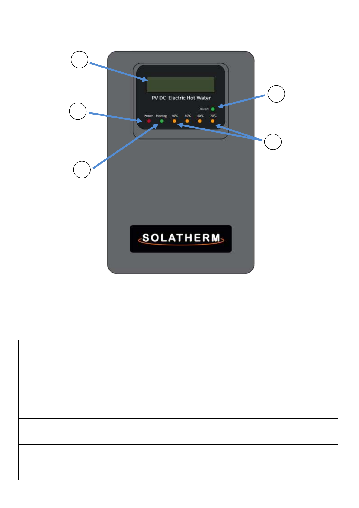
Display
Solatherm Control Units are independent from the grid and require no mains
power connection to operate, hence, the unit will only operate and display
user information when there is sufficient energy from the sun. It is normal for
the LCD display and lights to flicker or not fully display in low light conditions.
1
LCD Display
Scrolling display showing the array voltage and when the heating element is
activated, the current and power. The second line shows the kW/h consumed for
the day and the total kW/h consumption.
2
Power
(red)
LED illuminated red when the main array is connected and supplying power to
the unit. In low light conditions this light may be the only LED lit or flashing.
3
Heating
(green)
LED illuminated green when the controller has energized the heating element.
4
400-700C
(orange)
LED's illuminated orange - an approximate indication of the average temperature
of the water stored in the storage vessel.
5
Divert LED
(green)
PV360SWT: Green LED will illuminate when the heating element is switched off
and the secondary output is switched on.
PV360BMS: Green LED will flash when the output load is shared (Hot water and
diversion) and will remain on when the second output is 100%.
1
2
3
4
Figure 1.
5
7 | P a g e
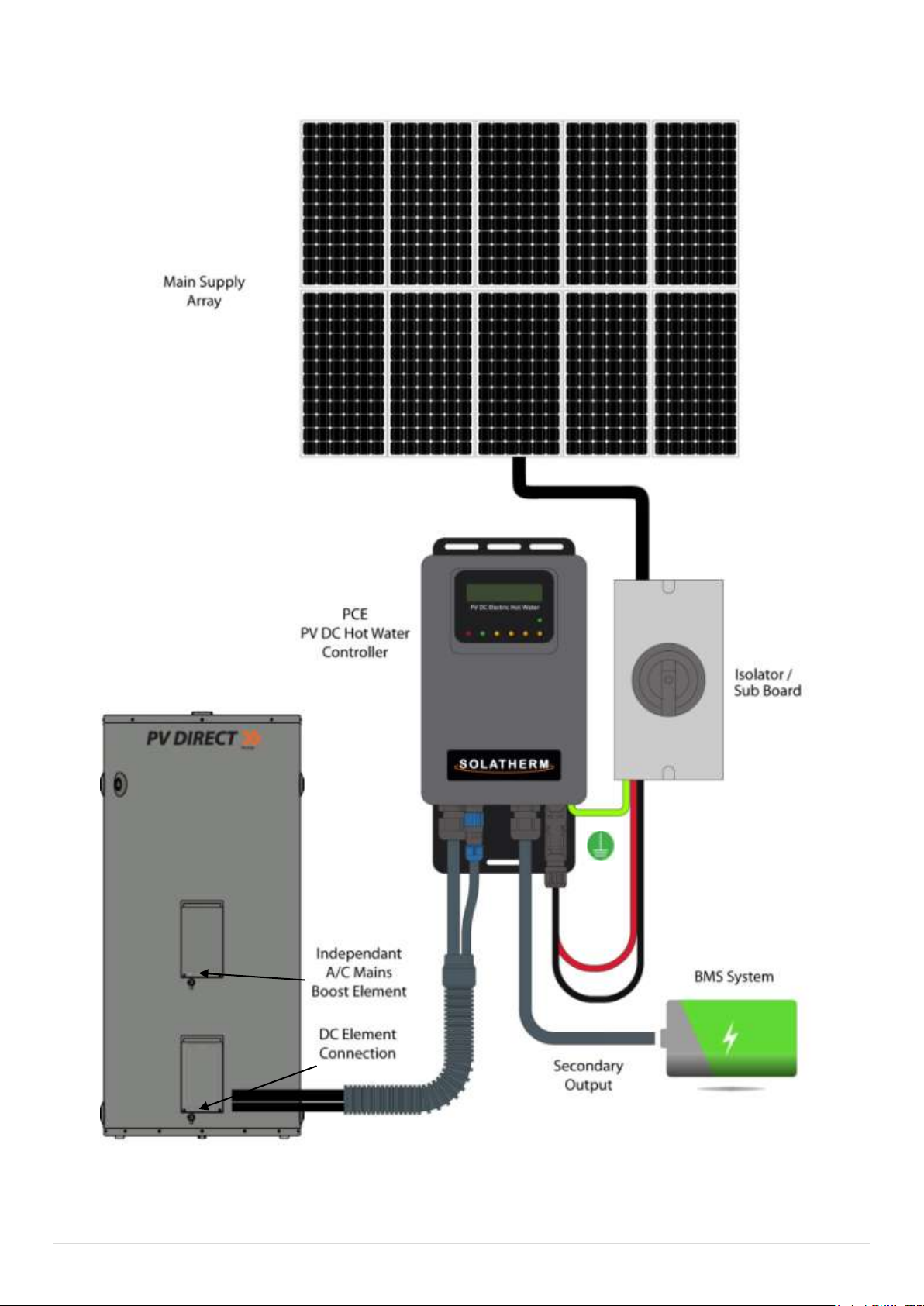
Basic System Configuration
Figure 2.

8 | P a g e
Start-up Procedure
NOTE: ENSURE HOT WATER VESSEL IS COMPLETELY FILLED WITH WATER
BEFORE COMENCING START UP PROCEDURE.
1. Turn on Isolator. RED LED POWER LIGHT SHOULD BE ON. The LCD will
illuminate and start to indicate incoming power (providing supply
voltage is over 40 Volts). The controller should show start up
information as it runs though a power up test sequence. When test is
complete LCD will display system voltage etc.
2. After the start up sequence is complete the green heating LED will light
up if sufficient power is available to commence heating. Note: The
controller has several built in time delays of up to 1.5 minutes, to allow
for power stabilisation. Some models will start on divert for 30min prior
to heating. See supplement.
3. Turn on 240V AC Booster breaker switch in household fuse box.
System Shutdown
1. Turn off main array isolator (lock switch if required)
2. Controller should now be off, red light and LCD display should be off.
3. Turn off 240V AC Booster isolator and breaker switch in household fuse
box.
4. System should now be electrically isolated.

9 | P a g e
Frequently Asked Questions
Q: The controller LCD and lights are flashing or resetting in the morning,
during the day or at the end of the day?
A: The Solatherm control unit is powered by the photovoltaic array. There is no
connection to mains/grid power required for standard operation. The controller
will only operate when sufficient energy is available from the sun. In low light,
such as in cloudy conditions, early in the morning or at the end of the day, it is
normal for the controller to flicker and dim and/or reset if there is inadequate
sunlight intensity to generate sufficient stable power for operation.
Q: My LCD show 0 Watts but the sun is out?
A:
1. The water in the storage tank is up to temperature.
Dependant on the factory set temperature 600C or 700C.
2. During periods of low light intensity such as, early morning, late evening or
in dark cloud the main array may not be able to produce the minimum
amount of power needed. The controller requires a stable 250 Watts to be
available when the element is energized to commence heating. The green
heating light will flick approximately every 25 seconds as the controller is
testing the amount of power available from the array.
Q: The heating light has been on all day but there is no hot water at the end
of the day?
A:
1. The hot water produced has been consumed during the day.
2. If the display is showing 0 Watts with the heating light on there may be a
fault with the element or the over temperature cut out. Please contact your
installer.

10 | P a g e
Q: Run out of hot water or warm water only.
A:
1. The hot water produced has been consumed during the day.
2. Not enough solar input during the day. Ensure booster is connected and
the AC boost timer settings are correct for the household demand or
season.
Q: I can see the second output is active but I have no hot water?
1. A: There is a fault with one of the temperature sensors and the controller
is in divert mode by default. The temperature lights on the controller will
be flashing with a fault. Please call your installer.

11 | P a g e
Troubleshooting
All observations for potential faults need to be conducted in clear daylight conditions.
Observation
Fault
Dim/flickering LCD display
& lights
Should this occur in bright sunshine please
contact your installer. No Fault if seen in low
light conditions. Re-check in brighter
conditions.
Please see note in Frequently Asked Questions
LCD continually resets with
35 second timer
During Periods of low light the LCD display may
be observed resetting in a loop until there is
sufficient power from the array to maintain
stability.
Flashing temperature
lights (Orange LEDs)
Fault with storage water temperature sensor or
internal temperature of the enclosure is too
high e.g. Controller mounted in full direct
sunshine or over voltage from array.
No heating light
(Green heating LED)
Element not powered. The controller will only
energise the element when there is enough
solar energy available and the storage water
temperature is below the set point. If clear
conditions, the water is cold and no green light
appears, contact your installer. Also see FAQ.
Heating light on but no hot
water. (Green Heating LED)
Not enough heating time has passed. Allow
more time for heating. If light is on but LCD
display shows no Power (Watt) figure contact
your installer. Possible Element Fault.
Flick of green light
(Green Heating LED)
Approximately every 20 seconds. This is the
unit testing the power available. A high voltage
may display but no current may be available.
Not enough sunlight to engage element.
No power light.
(Red LED)
Not enough power being produced by the main
array. If in sunny clear conditions contact your
installer.
No temperature lights
(Orange LEDs)
Average water storage temperature is below 32
degrees Celsius
12 | P a g e
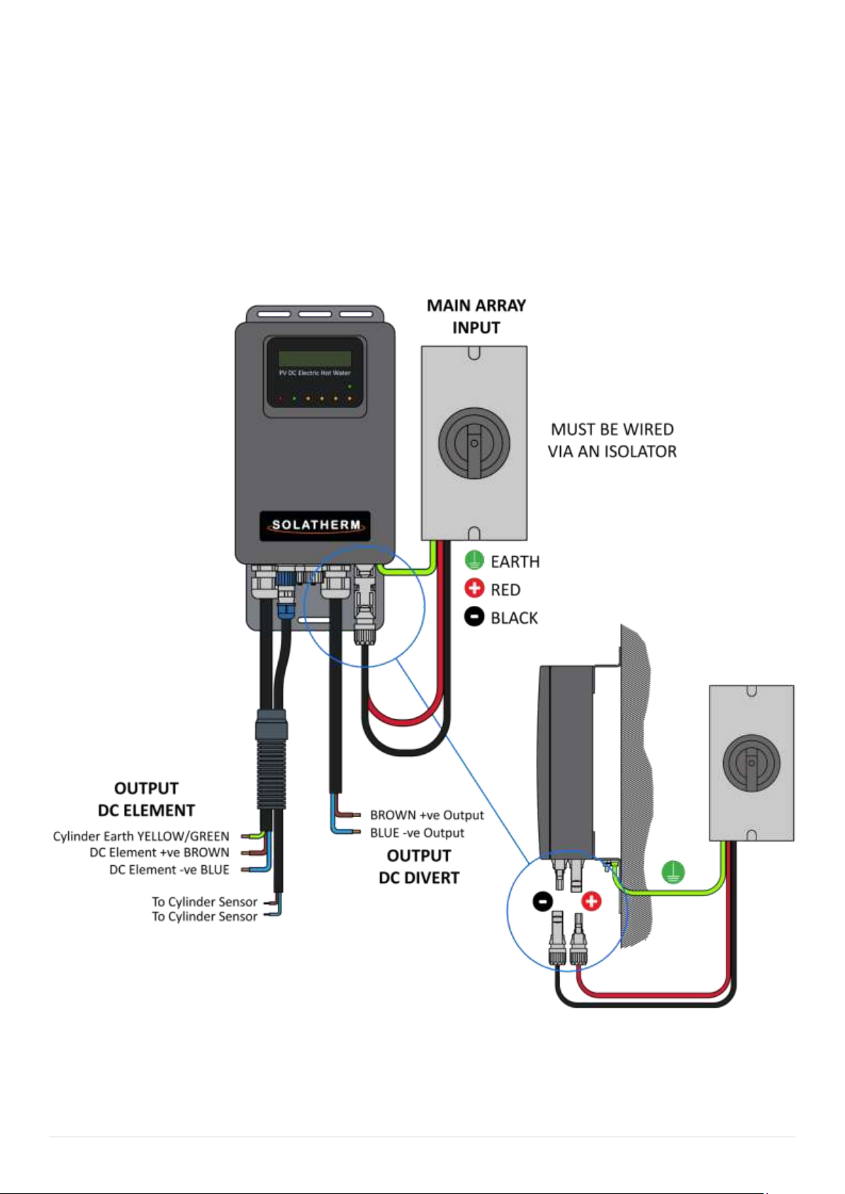
Installation Instructions
Wiring Diagram - Controller
WARNING INCORRECT POLARITY WILL DAMAGE THE CONTROLLER
NO WARRANTY FOR POLARITY DAMAGE
Figure 3.
13 | P a g e
On the Ground
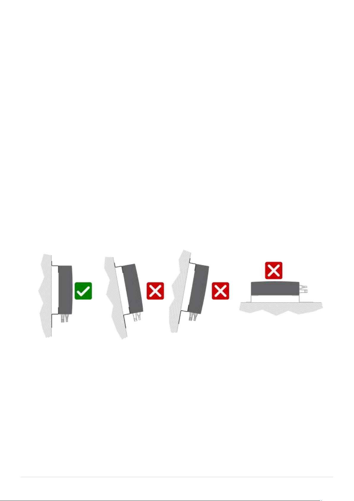
Wall mounting PCE controller
Choose a suitable location, giving consideration to the following:
1. Vertical wall mount at a height of between 1.5m to 2m above ground level
giving consideration to cable length and path to the Hot water vessel and
PV main array isolator location and diversion requirements.
2. It is important to mount the controller out of the direct sunlight as it will
make visual reading of the LCD display difficult.
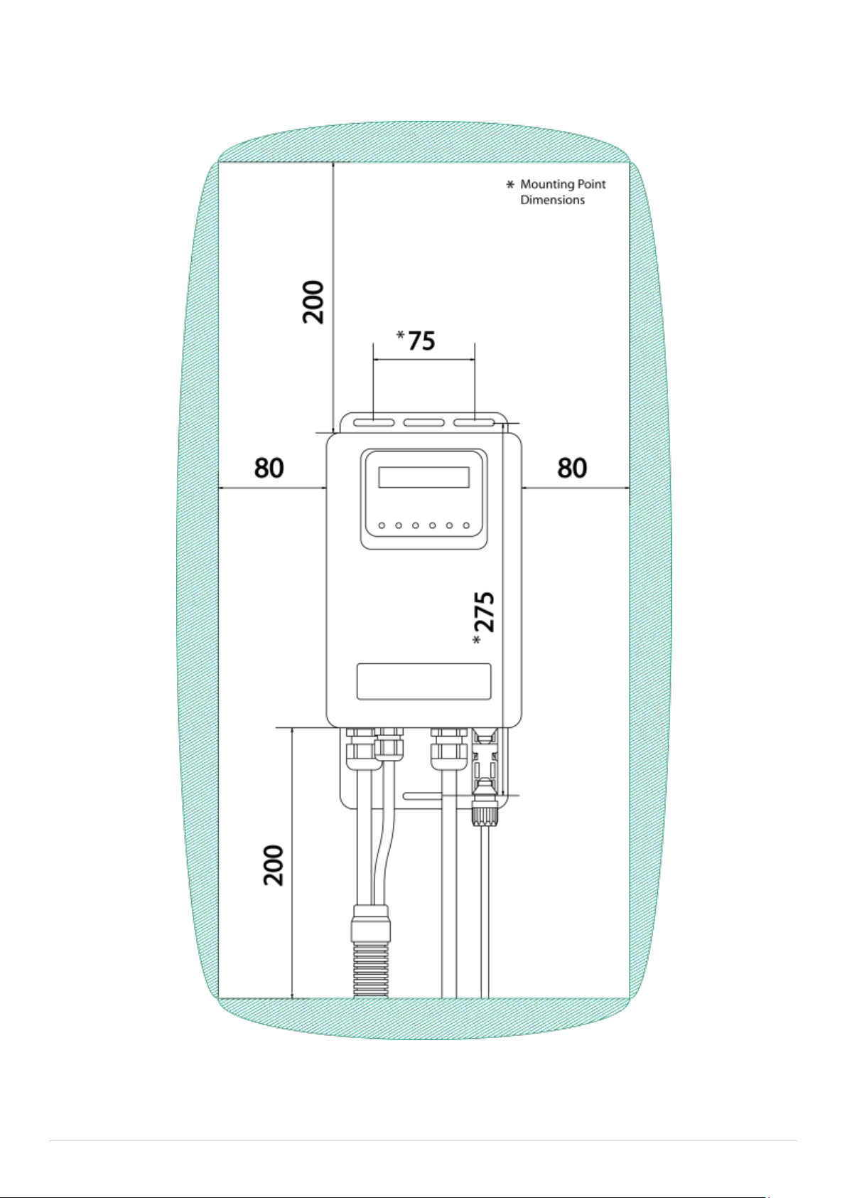
3. The control box shall be 3 x point screw mounted, via the attached slotted
metal brackets at the top and bottom of the controller e.g.: 2 x screws at
the top 1 x screw at the bottom. Determine preferred affixing mounting
screw method to suit wall substrate. The 2 x top screw holes shall be
80mm apart and the 1 x bottom screw hole shall be 275mm down central
to the top 2 x holes and control box. EG: (Like the capital letter T 80mm
across top & 275mm down).
Continued..
Figure 4
14 | P a g e
Mounting Clearances and Mount Point Locations
Figure 5

15 | P a g e
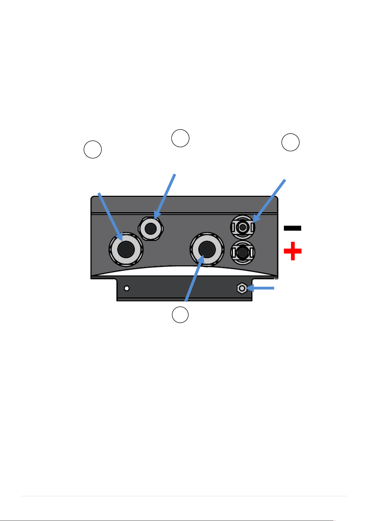
Connection: Controller to Storage Water Vessel
1. Remove lower DC element cover (figure2).
2. Route the 2.5m long flexible element output cable to the bottom element
inlet conduit elbow and thread both cables though up into element
cavity. It may be necessary to use a wire hook to help thread/ pass the 2 x
cables through the elbow. (It is important to have the first outer
insulation cover removed 200mm back exposing the 3 x insulated wires,
as passing the complete cable through the elbow is very tight). (Figure 6)
3. Terminate the element positive, negative & earth as per the instruction
label that is affixed to the inside of the element enclosure cover and per
the labelled colour coded connection points within.
4. Connect the 2 x colour coded NTC sensor wires into colour coded
mounting block.
See Figure 7: Wiring Diagram - PV OTC - Element
5. Ensure PVOTC which is spring located onto vessel surface has not been
disturbed during installation and is sitting in place and secure. Re-install
DC element cover (Figure 2).
6. Using the supplied cable saddles and removing and replacing base lid
screws to fit saddles, secure supply cable securely to the base of the hot
water tank.
7. Connect NTC connector to controller base.
PVOTC is only activated by overheating of the storage
vessel which indicates a potential system fault. The PVOTC
is a onetime operation and is NON RESETABLE. If activated
the PVOTC must be replaced.
Figure 6
16 | P a g e
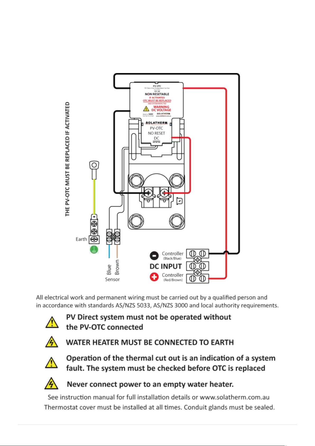
Wiring Diagram - PVOTC - Element
PVOTC is only activated by overheating of the storage vessel which indicates a potential
system fault. The PVOTC is a onetime operation and is NON RESETABLE.
If activated the PVOTC must to be replaced.
Figure 7.
17 | P a g e
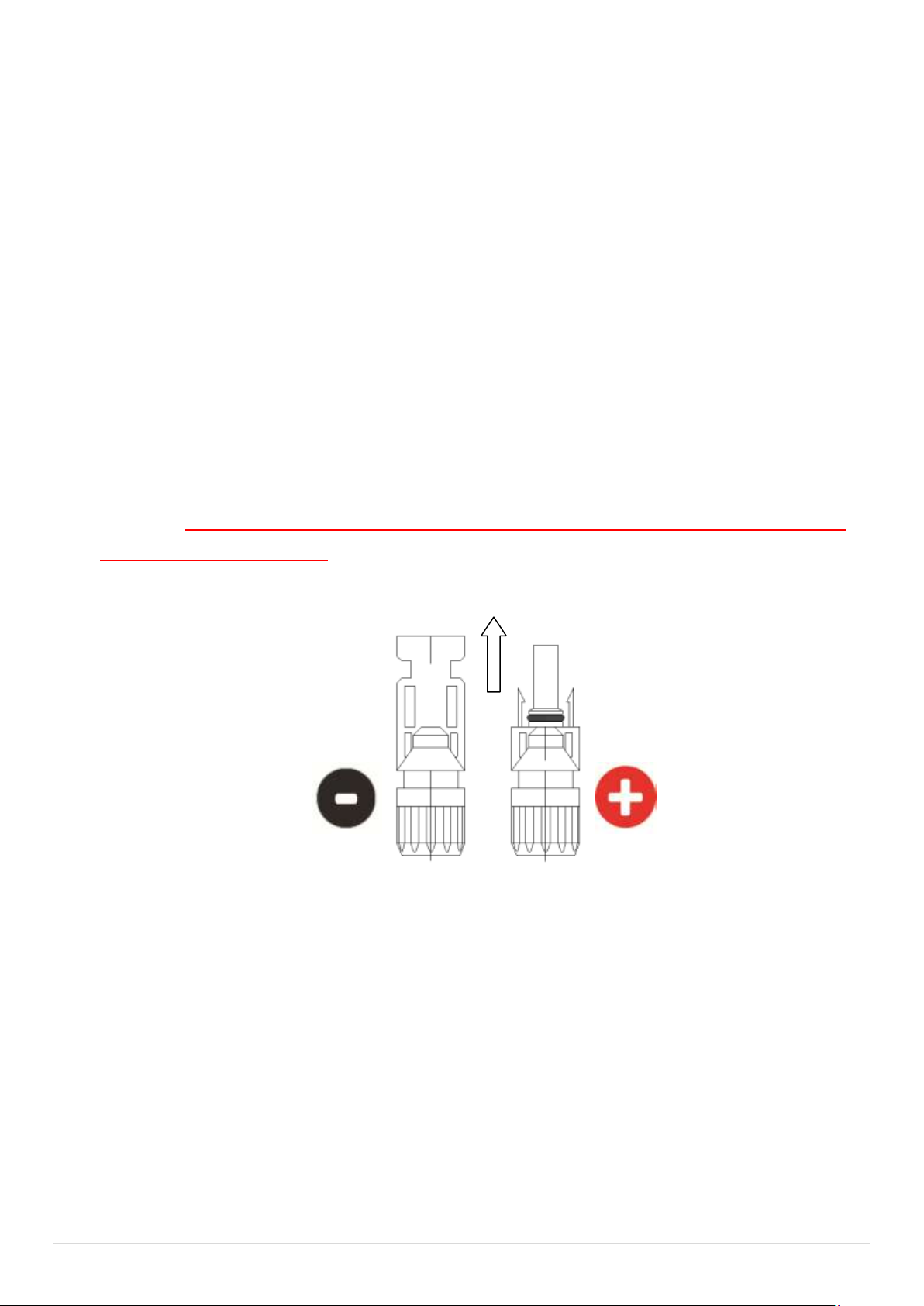
Connection - Main Array Input
1. Terminate cables with MC4 Connectors. Connect the cable to the Isolator.
Ensure Polarity on the MC4 connections is correct. TEST the polarity at the
MC4 connectors BEFORE CONNECTION TO THE CONTROLLER. Ensure to
connect the earth from the controller to the earth point from the main
array frame within the Isolator. Earth from controller and Array must be
connected to house ground point.
See Wiring Diagram - Controller - Figure 3
2. Test voltage from array. Confirm correct for controller model and cylinder
element.
3. Connect MC4 Connectors to controller input only when ready to
commission - See Commissioning Start up pg 19.
Ensure polarity at the MC4 connectors is correct before proceeding
further. TURN ISOLATOR ON AND TEST CORRECT POLARITY TO CONFIRM
BEFORE PROCEEDING.
IT IS IMPORTANT TO ENSURE THAT THE SUPPLY FROM THE MAIN ARRAY IS
TERMINATED POLLARITY CORRECT AND MUST BE CHECKED BEFORE
CONNECTION!!
THE CONTROLLER WILL BE DESTROYED IF REVERSE POLARITY CONNECTED!!
Incorrect polarity will void the warranty.
Positive on loom
from the Isolator
Negative on the loom from
the isolator
To Controller
From Array
Figure 8
18 | P a g e
Connection - Secondary Output
1. Terminate the 400mm long output diversion cable (D) into Isolator and
direct to auxiliary device as required.
See Wiring Diagram - Controller - Figure 3 and Figure 9.
Element
storage vessel
E
Main Array
via Isolator
A
NTC
Temperature
T
Figure 9.
EARTH
Secondary Output
D

19 | P a g e
Connection - Boost Element - AC
The 240V A/C Booster supply cable must be installed in accordance to
Australian Standard AS3000 and by a qualified person.
Note: Never energise the element until the water vessel is filled and
bled!
1. Remove top booster 240V A/C element cover.
2. Connect into the 25mm female elbow using 25mm flex conduit and
approved twin and earth cable suitable for the booster element fitted.
3. Following the wiring instructions affixed inside the cover, (The standard
booster element is 2.4Kw 10Amp but this may vary depending on
application ensure to identify and wire to suit load).
The hot water vessel must be connected to Earth.
**Note**
Consideration must be given to the local power supply offerings to
maximise operation of the PV solar contribution. E.g.: In locations where a
controlled load (off peak) is available the booster supply ideally should be
connected to this tariff. In locations where only peak supply power is
available, it is recommended to fit an A/C supply timer which can be set to
the individual requirements of the end user.
This manual suits for next models
1
Table of contents
Popular Water System manuals by other brands


Pentair
Pentair EVERPURE CONSERV LT-S manual

FLOWTECH
FLOWTECH flowvess Operation and maintenance manual

Graf
Graf one2clean Service instructions

DeDietrich
DeDietrich DU15 manual

Kemper
Kemper KHS-HS2 689 03 001 Installation and operating instruction

Abundant Flow Water Systems
Abundant Flow Water Systems RO/DI Combo System Installation & service manual