Hotsy CWC Series User manual

9.801-695.0-A
OPERATOR'S MANUAL
CWC
STATIONARY
COLD WATER SERIES
®
c
L
I
S
T
E
D
®
98016960-1
GROUND
GROUND
TACH/HOUR
EXPOSED PULLEYS AND
BELTS CAN CAUSE INJURY
KEEPCLEAR WHILE MACHINERY
ISOPERATING
POLEASYCORREAS EX PUESTAS
PUEDEN CAUSARDAÑ O
NOSE ACERQUE SI MÀQUINA ESTÁ FUNCIONANDO
DES COURROIES OU POULIES EX POSÉES
PEUVENT CAUSER DES BLESSURES
NEPAS S’APPROCHER LORSQUE L’APPAREIL EST EN OPÉRATION
WARNING
PRECAUCIÓN/ AVERTISSEMENT
8.932-965.0
OPERATING INSTRUCTIONS
WAR NIN G / PRECAUCION / AVERTISSEMENT
MODE D’EMPLOI
INSTRUCCIONESDE OPERACION
EXPOSED PULLEYS AND
BELTSCAN CAUSE INJURY
KEEPCLEAR WHILE MACHINERY
ISOPERATING
POLEASY CORREAS EXPUESTAS
PUEDENCAUSAR DAÑO
NOSE ACERQUE SI MÀQUINA ESTÁ FUNCIONANDO
DESCOURROIES OU POULIES EXPOSÉES
PEUVENTCAUSER DES BLESSURES
NEPAS S’APPROCHER LORSQUE L’APPAREILEST EN OPÉRATION
WARNING
PRECAUCIÓN/ AVERTISSEMENT
8.932-965.0


1.106-572.0 CWC-53 SPECIFICATIONS
● Pump Volume At Pump Head: 3.9 GPM/234 GPH
● Pump Pressure At Pump Head: 3000 PSI
● Motor Hp: 7.5
● Machine Voltage: 230VAC/60Hz/1Ph
● Total Machine Amperage: 36 Amps
● Machine Weight: 289 Lbs.
● Shipping Weight: 340 Lbs.
● Machine Dimensions: 24.25 X 21 X 36
1.106-573.0 CWC-54 SPECIFICATIONS
● Pump Volume At Pump Head: 3.9 GPM/234 GPH
● Pump Pressure At Pump Head: 3000 PSI
● Motor Hp: 7.5
● Machine Voltage: 230VAC/60Hz/3Ph
● Total Machine Amperage: 23 Amps
● Machine Weight: 289 Lbs
● Shipping Weight: 340 Lbs
● Machine Dimensions: 24.25 X 21 X 36
1.106-574.0 CWC-55 SPECIFICATIONS
● Pump Volume At Pump Head: 3.9 GPM/234 GPH
● Pump Pressure At Pump Head: 3000 PSI
● Motor Hp: 7.5
● Machine Voltage: 460VAC/60Hz/3Ph
● Total Machine Amperage: 11 Amps
● Machine Weight: 289 Lbs
● Shipping Weight: 340 Lbs
● Machine Dimensions: 24.25 X 21 X 36
1.106-575.0 CWC-56 SPECIFICATIONS
● Pump Volume At Pump Head: 3.9 GPM/234 GPH
● Pump Pressure At Pump Head: 3000 PSI
● Motor Hp: 7.5
● Machine Voltage: 575VAC/60Hz/3Ph
● Total Machine Amperage: 9 Amps
● Machine Weight: 289 Lbs
● Shipping Weight: 340 Lbs
● Machine Dimensions: 24.25 X 21 X 36
1.106-576.0 CWC-63 SPECIFICATIONS
● Pump Volume At Pump Head: 4.95 GPM/297 GPH
● Pump Pressure At Pump Head: 2000 PSI
● Motor Hp: 7.5
● Machine Voltage: 230VAC/60Hz/1Ph
● Total Machine Amperage: 28 Amps
● Machine Weight: 289 Lbs
● Shipping Weight: 340 Lbs
● Machine Dimensions: 24.25 X 21 X 36
1.106-577.0 CWC-64 SPECIFICATIONS
● Pump Volume At Pump Head: 4.95 GPM/297 GPH
● Pump Pressure At Pump Head: 2000 PSI
● Motor Hp: 7.5
● Machine Voltage: 230VAC/60Hz/3Ph
● Total Machine Amperage: 18 Amps
● Machine Weight: 289 Lbs
● Shipping Weight: 340 Lbs
● Machine Dimensions: 24.25 X 21 X 36
1.106-578.0 CWC-65 SPECIFICATIONS
● Pump Volume At Pump Head: 4.95 GPM/297 GPH
● Pump Pressure At Pump Head: 2000 PSI
● Motor Hp: 7.5
● Machine Voltage: 460VAC/60Hz/3Ph
● Total Machine Amperage: 9 Amps
● Machine Weight: 289 Lbs.
● Shipping Weight: 340 Lbs.
● Machine Dimensions: 24.25 X 21 X 36
1.106-579.0 CWC-66 SPECIFICATIONS
● Pump Volume At Pump Head: 4.95 GPM/297 GPH
● Pump Pressure At Pump Head: 2000 PSI
● Motor Hp: 7.5
● Machine Voltage: 575VAC/60Hz/3Ph
● Total Machine Amperage: 8 Amps
● Machine Weight: 289 Lbs.
● Shipping Weight: 340 Lbs.
● Machine Dimensions: 24.25 X 21 X 36

SYMBOLS
Not all machines have all symbols
Identification of Operational Label Symbols
Pump Switch
Hour Meter
Detergent
Voltage
When the light is on, it means power supply is on
Motor Overload
When the light is on, it means the overload is tripped.
Reset overload.

5
CONTENTS
HOTSY • CWC OPERATOR'S MANUAL • 9.801-695.0 • Rev. 7/14
Model Number ______________________________
Serial Number ______________________________
Date of Purchase ____________________________
The model and serial numbers will be found on a decal attached
to the pressure washer. You should record both serial number and
date of purchase and keep in a safe place for future reference.
Introduction & Important Safety Information 6-7
Component Identification 8
Assembly Instructions 9
Operating Instructions 10-11
Shutdown Instructions 11
Maintenance 12
Smart Relay Instructions 13-15
Optional Water Inlet Instructions 16
Troubleshooting 17-19

HOTSY • CWC OPERATOR'S MANUAL • 9.801-695.0 • Rev. 7/14
OPERATOR’S MANUAL PRESSURE WASHER
6
INTRODUCTION & IMPORTANT SAFETY INFORMATION
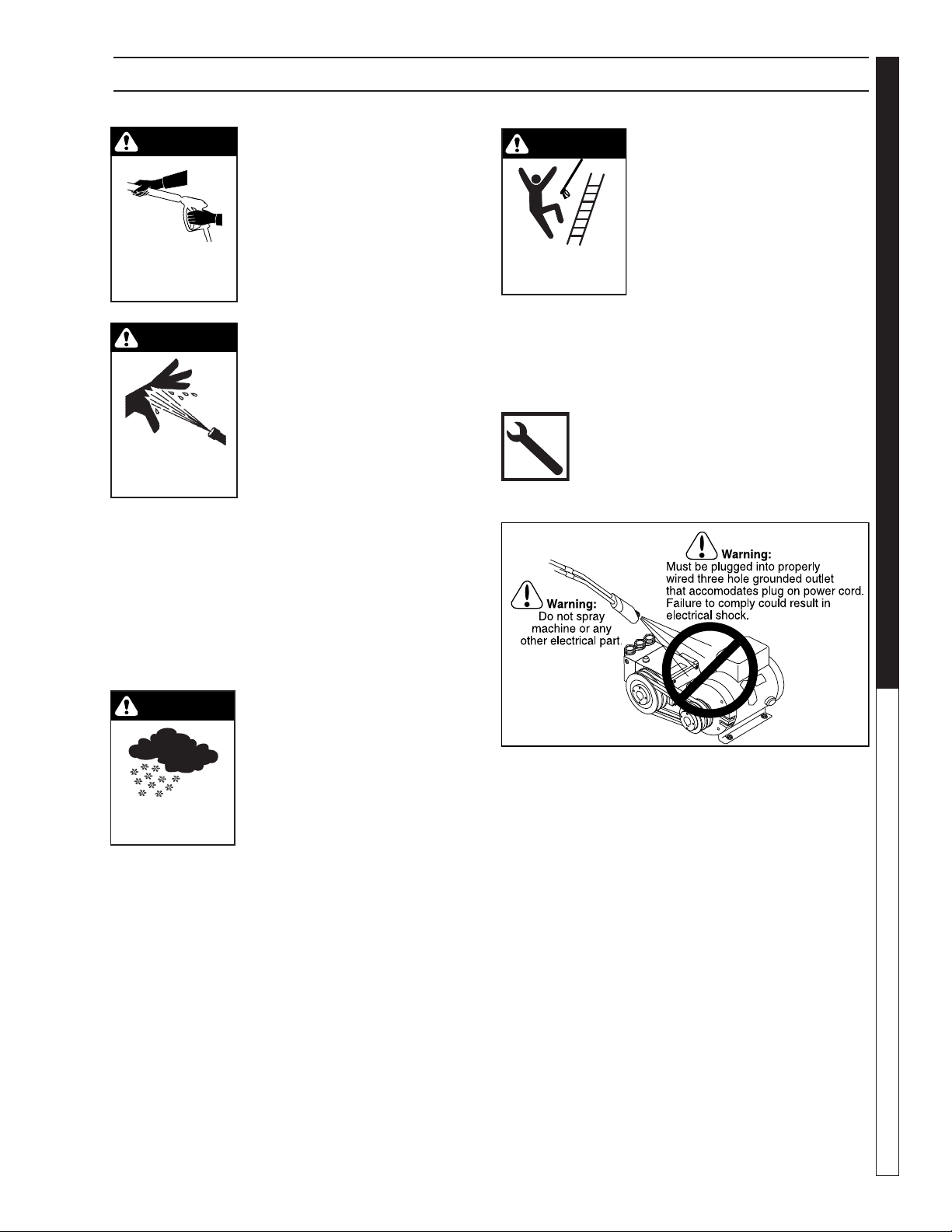
DANGER: Improper connection of the equipment-
grounding conductor can result in a risk of
electrocution.Check with a qualified electrician
or service personnel if you are in doubt as to
whether the outlet is properly grounded. Do
not modify the plug provided with the product
- if it will not fit the outlet, have a proper outlet
installed by a qualified electrician. Do not use
any type of adaptor with this product
WARNING
KEEP WATER
SPRAY AWAY FROM
ELECTRICAL WIRING.
WARNING:Keep wand,hose, and
water spray away from electric
wiring or fatal electric shock
may result.
5. To protect the operator from
electrical shock, the machine
must be electrically grounded.
It is the responsibility of the
owner to connect this
machine to a UL grounded receptacle of proper
voltage and amperage ratings. Do not spray water
on or near electrical components. Do not touch
machine with wet hands or while standing in water.
Always disconnect power before servicing.
RISK OF EXPLOSION:
DO NOT SPRAY
FLAMMABLE
LIQUIDS.
WARNING
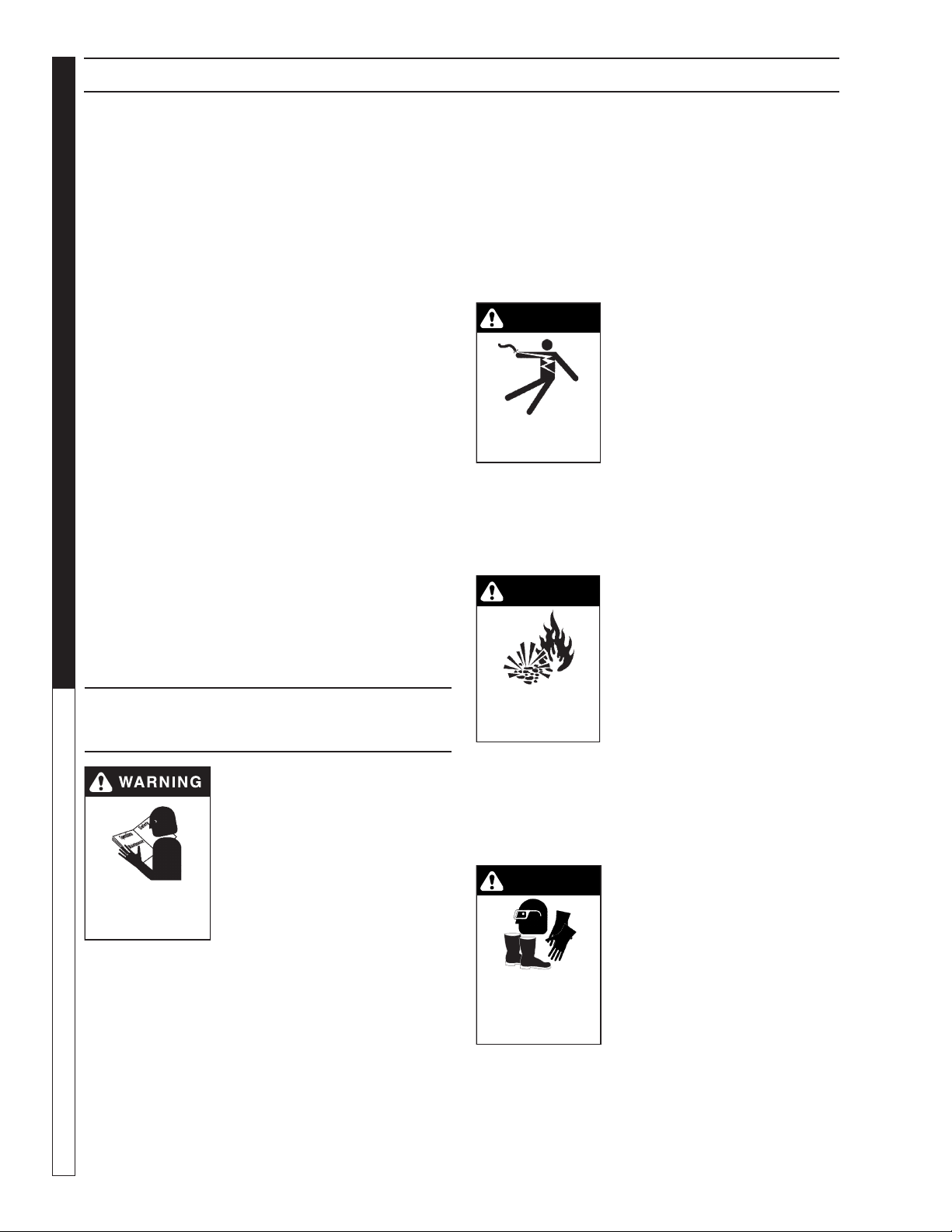
WARNING: Flammable liquids
can create fumes which can ig-
nite, causing property damage
or severe injury.
WARNING: Risk of explosion —
Do not spray flammable liquids.
6. Do not allow acids, caustic or abrasive fluids to
pass through the pump.
7. Never run pump dry or leave spray gun closed
longer than 1-2 minutes.
8. Keep operating area clear of all persons.
WARNING
USE PROTECTIVE
EYE WEAR
AND CLOTHING
WHEN OPERATING
THIS EQUIPMENT.
WARNING:High pressure spray
can cause paint chips or other
particles to become airborne
and fly at high speeds.To avoid
personal injury, eye, hand and
foot safety devices must be
worn.
9. Eye, hand, and foot protection
must be worn when using this
equipment.
Thank you for purchasing this Pressure Washer.
We reserve the right to make changes at any time
without incurring any obligation.
Owner/User Responsibility:
The owner and/or user must have an understanding of
the manufacturer’s operating instructions and warnings
before using this pressure washer.Warning information
should be emphasized and understood. If the operator
is not fluent in English, the manufacturer’s instructions
and warnings shall be read to and discussed with
the operator in the operator’s native language by the
purchaser/owner, making sure that the operator com-
prehends its contents.
Owner and/or user must study and maintain for future
reference the manufacturers’ instructions.
The operator must know how to stop the machine
quickly and understand the operation of all controls.
Never permit anyone to operate the machine without
proper instructions.
SAVE THESE INSTRUCTIONS
This manual should be considered a permanent
part of the machine and should remain with it if
machine is resold.
When ordering parts, please specify model and
serial number. Use only identical replacement parts.
This machine is to be used only by trained operators.
IMPORTANT SAFETY
INFORMATION
READ OPERATOR’S
MANUAL THOROUGHLY
PRIOR TO USE.
WARNING:To reduce the risk of
injury, read operating instruc-
tions carefully before using.
1. Read the owner's manual
thoroughly. Failure to follow
instructions could cause mal-
function of the machine and
result in death, serious bodily
injury and/or property dam-
age.
2. Know how to stop the machine and bleed pressure
quickly. Be thoroughly familiar with the controls.
3. Stay alert — watch what you are doing.
4. All installations must comply with local codes.
Contact your electrician, plumber, utility company
or the selling distributor for specific details.

HOTSY • CWC OPERATOR'S MANUAL • 9.801-695.0 • Rev. 7/14
7
PRESSURE WASHER OPERATOR’S MANUAL
IMPORTANT SAFETY INFORMATION
TRIGGER GUN KICKS
BACK - HOLD WITH
BOTH HANDS
WARNING
WARNING: Grip cleaning wand
securely with both hands before
starting. Failure to do this could
result in injury from a whipping
wand.
RISK OF INJECTION
OR SEVERE INJURY
TO PERSONS. KEEP
CLEAR OF NOZZLE.
WARNING
WARNING:High pressure devel-
oped by these machines will
cause personal injury or equip-
ment damage. Keep clear of
nozzle. Use caution when oper-
ating. Do not direct discharge
stream at people, or severe in-
jury or death will result.
10. To reduce the risk of injury, close supervision is
necessary when a machine is used near children.
Do not allow children to operate the pressure
washer. This machine must be attended during
operation.
11. Never make adjustments on machine while in
operation.
12. Be certain all quick coupler fittings are secured
before using pressure washer.
WARNING
PROTECT FROM
FREEZING
WARNING:Protect machine from
freezing.
13. To keep machine in best
operating conditions, it is
important you protect machine
from freezing.Failure to protect
machine from freezing could
cause malfunction of the
machine and result in death,
serious bodily injury, and/or property damage. Fol-
low storage instructions specified in this manual.
14. Inlet water must be clean fresh water and no hotter
than 90°F.
15. Manufacturer will not be liable for any changes
made to our standard machines or any components
not purchased from us.
16. The best insurance against an accident is precau-
tion and knowledge of the machine.
WARNING
RISK OF INJURY
FROM FALLS WHEN
USING LADDER.
WARNING:Be extremely careful
when using a ladder, scaffold-
ing or any other relatively un-
stable location. The cleaning
area should have adequate
slopes and drainage to reduce
the possibility of a fall due to
slippery surfaces.
17. Do not overreach or stand on unstable support.
Keep good footing and balance at all times.
18. Do not operate this machine when fatigued or
under the influence of alcohol, prescription medi-
cations, or drugs.
19. Follow the maintenance instruc-
tions specified in the
manual.

HOTSY • CWC OPERATOR'S MANUAL • 9.801-695.0 • Rev. 7/14
OPERATOR’S MANUAL PRESSURE WASHER
8
COMPONENT IDENTIFICATION
Pump — Develops high pressure by pumping water
volume through nozzle.
Spray Gun — Controls the application of water and
detergent onto cleaning surface with trigger device.
Includes safety latch.
Detergent Metering Valve — Controls detergent
mixture.
Wand — Must be connected to the spray gun.
High Pressure Hose — Connect one end to water
pump discharge nipple and the other end to spray gun.
Pressure Nozzle — Inserted into wand quick coupler
to develop pressure
SafetyTrigger Lever — Prevents accidental triggering
of spray gun while inserting a high pressure nozzle.
98016960-2
GROUND
GROUND
TACH/HOUR
EXPOSED PULLEYS AND
BELTS CAN CAUSE INJURY
KEEPCLEAR WHILE MACHINERY
ISOPERATING
POLEAS Y CORREAS EXPUESTAS
PUEDEN CAUSARD AÑO
NOSE ACERQUE SI MÀQUINA ESTÁ FUNCIONANDO
DES COURROIES OU POULIES EXP OSÉES
PEUVENT CAUSER DES BLESSURES
NEPAS S’APPROCHER LORSQUE L’APPAREIL EST EN OPÉRATION
WARNING
PRECAUCIÓN/ AVERTISSEMENT
8.932-965.0
OPERATING INSTRUCTIONS
WARN ING / PRECAUCION / AVERTISSEMENT
MODE D’EMPLOI
INSTRUCCIONESDE OPERACION
EXPOSED PULLEYS AND
BELTS CAN CAUSE INJURY
KEEPCLEAR WHILE MACHINERY
ISOPERATING
POLEASY CORREAS EXPUESTAS
PUEDENCAUSAR DAÑO
NOSE ACERQUE SI MÀQUINA ESTÁ FUNCIONANDO
DES COURROIES OUPOULIES EXPOSÉES
PEUVENTCAUSER DES BLE SSURES
NEPAS S’APPROCHER LORSQUE L’APPAREILEST EN OPÉRATION
WARNING
PRECAUCIÓN/ AVERTISSEMENT
8.932-965.0
High Pressure
Hose
Inlet Power
Junction Box
Pump Switch
Wand
Garden Hose
(not included)
Detergent
Metering
Valve
Nozzles
Detergent Bucket
(not included)
Spray Gun
High Pressure
Nozzle
Safety Trigger
Lever
Detergent
Inlet
Water
Outlet

HOTSY • CWC OPERATOR'S MANUAL • 9.801-695.0 • Rev. 7/14
9
PRESSURE WASHER OPERATOR’S MANUAL
98016960-3
ASSEMBLY INSTRUCTIONS
Unpacking
Unpack carefully.Wear safety glasses or goggles while un-
packing, assembling or operating pressure washer. If there
are missing components or hidden damage immediately
contact distributor or carrier concerning discrepancies.
1. Cut strapping band from pressure washer
and pallet.
2. Remove pressure washer from pallet.
Parts Included
• Pressure Washer
• Pressure Hose
• Wand
• Parts Box Containing:
■Pressure Nozzles (3 on machine).
■Trigger Gun
• Operating Instructions and Parts Manual
Tools Required
• 10" Adjustable Crescent Wrenches (2 ea.)
• Blade Screwdriver
Pressure Hose, Wand and Wand Holder
1. Use teflon tape on plumbing connections to prevent
leakage.
2. Install pressure hose on machine as shown.
3. Assemble wand components as shown.Connect
pressure hose to trigger gun.
NOTE:The nozzle is not to be installed at this time.
4. Make sure that all plumbing connections are tight.
Pressure Hose
coupler
98016960-13
Wand
Pressure Hose
Trigger Gun
Quick Disconnect Plug
Quick
Disconnect

HOTSY • CWC OPERATOR'S MANUAL • 9.801-695.0 • Rev. 7/14
OPERATOR’S MANUAL PRESSURE WASHER
10
OPERATING INSTRUCTIONS
To Clean
WARNING: Risk of injection or severe injury - Keep
clear of nozzle - DO NOT direct discharge stream at
persons - This machine is to be used only by quali-
fied operators.
AVERTISSEMENT: RISQUE D’INJECTION ET DE
BLESSURES GRAVES. SE TENIR À L’ÉCART DU JET.
NE PAS DIRIGER LE JET DE SORTIEVERS D’AUTRES
PERSONNES. CONFIER L’UTILISATION DE CE MATÉ-
RIEL À UN OPÉRATEUR QUALIFIÉ.
1. Insert detergent inlet line into container of mixed
detergent. Open detergent ON/OFF valve. The
detergent will be pulled automatically into the sys-
tem. Allow detergent to reach end of wand before
proceeding to step 3.
2. Select pressure nozzle with spray pattern that match-
es your cleaning needs. Engage manual trigger lock
and install selected nozzle.
3. Wash from the bottom to the top, using side to side
motions.This washes away heavy dirt and allows the
detergent to soak as you work toward the top.
4. Do not wash at a 90° angle to the work (straight at
it). This will allow water to splash back at you and
reduces your cleaning power. Wash at a 30° to 60°
angle to the work. This will allow the water to splash
away from you and the water will wash the dirt away
faster and easier.
5. Use the width of the spray pattern to wash in a wide
path. Overlap spray paths for complete coverage.
Wash from side to side, using slow, steady motions.
6. The nozzle should be 12" to 24" from work, closer
for tough areas. Be careful on painted or delicate
surfaces, the pressure may damage surface if nozzle
is too close.
7. Small parts should be washed in a basket and larger,
lightweight parts should be clamped down so the
pressure does not push them away.
8. Close the detergent ON/OFF valve to permit rinse.
Always rinse with cold water after using detergents.
Rinse from the top to the bottom to prevent detergent
from dripping onto a rinsed area. For the best results,
contact your Hotsy dealer to help you select the best
detergent for your application.

HOTSY • CWC OPERATOR'S MANUAL • 9.801-695.0 • Rev. 7/14
11
PRESSURE WASHER OPERATOR’S MANUAL
OPERATING INSTRUCTIONS
PRE-OPERATION CHECK
Read machine safety warnings
Pump oil (SAE 30W (non-detergent oil))
Cold water supply (1gpm over machines rating •
5/8" • 20 psi)
Proper power supply and circuit protection
Hose, wand, nozzles (nozzle sizes per serial plate)
Water filter (intact, non restrictive)
Read operation instructions
This machine must be protected from the elements/
freezing.
SET-UP PROCEDURES
This machine is intended for indoor use. Machine
must be stored indoors when not in use.
1. Attach a minimum 5/8" garden hose to inlet con-
nector. Minimum flow should be 1 gpm over the flow
rate of the pressure washer.
2. Attach high pressure hose to discharge nipple us-
ing quick coupler. Lock coupler securely into place
by pulling back coupler collar and inserting it onto
dis-charge nipple, then pushing collar forward to
lock in place.
3. Attach wand to spray gun using teflon tape on
threads to prevent leakage.
4. Attach connector on discharge hose to spray gun
using teflon tape on threads.
5. Remove oil plug on top of pressure washer pump
and replace with dipstick supplied. (This may be
installed from the factory.)
6. Check oil level on oil dipstick on top of pump. Oil
should be visible one half way up sight glass (30W
non-detergent).
OPERATING INSTRUCTIONS
1. Read safety and preventative maintenance in-
structions before starting machine.
2. Turn on water at faucet and pull trigger on spray
gun allowing water to flow until all air has dis-
charged from system. Check for water leaks;
tighten as needed.
3. Push the pump switch on.
4. Turn the variable pressure control handle clock-
wise to increase pressure.
5. To apply detergent read “How to Use The Deter-
gent Injector.”
SHUT DOWN PROCEDURES
1. Rinse with clean water to remove any soap resi-
due, by placing detergent hose into fresh water
bucket and operating injector as described below.
2. Release the trigger on the spray gun. Turn the
switch off if the machine is going to be left unat-
tended. (Time delay only).
3. Turn off water supply.
4. Open spray gun to relieve remaining pressure.
5. Remove water supply hose.
98016960-4
IMPORTANT:The trigger gun provided with this pres-
sure washer is equipped with a manual trigger lock to
prevent accidental operation of the trigger gun, refer
to figure above.The safety trigger lock should be used
whenever the trigger gun is not in use.
Trigger
High
Pressure
Nozzle

HOTSY • CWC OPERATOR'S MANUAL • 9.801-695.0 • Rev. 7/14
OPERATOR’S MANUAL PRESSURE WASHER
12
WARNING: Unauthorized machine modification or
use of non-approved replacement parts may cause
personal injury and/or property damage and will void
the manufacturer warranty.
Pump
Use Hotsy Pump Oil (8.914-527.0) for pump crankcase.
Crankcase must be filled to the full mark on the dipstick
or to center of sight glass window found on the rear of
the pump. During the break-in-period, make sure the oil
is changed after the first 25 hours of operation. After that,
replace oil every 3 months or 300 hours of operation,
whichever comes first.
Proper Pump Care:
• Do not pump acids.
• Do not allow pump to run dry.
• Winterize if storing in freezing temperatures; refer
to Storage for details.
• Use a water softener on the water system if known
to be high in mineral content.
• Use only high quality detergents and follow manu-
facturer’s mix recommendations.
• Flush the system with clear water immediately after
using detergent solutions.
• Clean filter screen on detergent inlet line periodically.
• Flush the pressure washer system with antifreeze
if storing for an extended period of time; refer to
Storage for details.
MAINTENANCE
Pump Motor
On a yearly basis, oil pump motor per instructions on
motor nameplate.
NOTE: Some motors may be equipped with perma-
nently lubricated bearings and will not require ad-
ditional lubrication.
Unloader Valve
WARNING: The unloader valve on this pressure
washer has been factory set and sealed and is a field
nonadjustable part.Tampering with the factory setting
may cause personal injury and/or property damage,
and will void the manufacturer warranty.
98016960-14
Dipstick
Sight Glass
(on Rear of Pump)
Oil Fill

HOTSY • CWC OPERATOR'S MANUAL • 9.801-695.0 • Rev. 7/14
13
PRESSURE WASHER OPERATOR’S MANUAL
SMART RELAY INSTRUCTIONS
DIGITAL TIMER (OPTIONAL)
The following are instructions on how to set the pa-
rameters on the digital timer in Programming Mode.
To define these settings please follow the steps below.
Setting the Clock:
1. Press the ESC key located next to the display
window and under the arrow key pad (see figure
below). Pressing the ESC key will access the
Parameter Assignment Menu.
2. Using the up/down arrow keys ▲ or ▼, move the
(>) cursor to 'Set' and press OK to accept.
3. Move the (>) cursor to 'Clock' and press OK to
accept.
4. Move the (>) cursor to 'Set Clock' and press OK
to accept 'Set Clock'.
NOTE: When setting time on clock, use only mili-
tary time.
Stop
Set Param
> Set..
Prg Name
> Clock
Contrast
StartScreen
> Set Clock
S/W Time..
Sync
Mo 10:15
2006-10-13
ESC OK
Display Screen
Arrow
Key Pad
The cursor is now positioned on the weekday and
shows the following on the display window (see figure
below).
5. Select the day of the week by using the up/down
arrow keys or .
6. Move the cursor to the next position by using the
left/right arrow keys or .
7. To change the value use the up/down arrow keys
or .
8. To set the correct time-of-day and date, repeat
steps 6 and 7.
9. To accept your entries press OK.
10. To go back to the previous menu at anytime press
ESC.
PROGRAMMING
INSTRUCTIONS
The CWC can be configured to run in Time Delay or
Auto Start/Stop with lockout. Machines are factory set
with Auto Start/Stop with 4 hour Lockout. A Smart Relay
controls how the machine will operate by using three in-
ternal timers; these timers are adjustable. The following
is a brief description of these timers:
Timer 1: ‘Lockout Timer’ (Time Delay)
• Timer 1 de-energizes (lockout) the machine if
not being used for a preset time. If machine has
‘Locked out’ it can only be re-energize by pressing
the ‘Pump On’ switch. Timer 1 is factory set to 4
hours.
Timer 2: ‘Auto Start/Stop Timer’
• Timer 2 allows the pump to run in bypass for a
preset time. If the pump runs in bypass longer
than the allotted time the timer will drop power to
the motor contactor and machine will be in standby
mode. Squeezing the gun trigger will restart the
pump (if Timer 1 has not locked out). Timer 2 is
factory set to 30 seconds.
Timer 3: ‘Reset Delay Timer’
• Timer 3 controls how long the pump must run be-
fore resetting the ‘Lockout Timer’ (Timer 1). This al-
lows the pump to run long enough to re-pressurize
the system if there is pressure loss when not in
use. Timer 3 is factory set to 15 seconds.
Set Clock
Mo 10:15
YYYY-MM-DD
2006-10-13

HOTSY • CWC OPERATOR'S MANUAL • 9.801-695.0 • Rev. 7/14
OPERATOR’S MANUAL PRESSURE WASHER
14
To change to the parameters of the internal timers in the
Smart Relay complete the following steps:
1. Turn on the power to the machine but do not press
the start switch. Remove the front panel and then
the control panel cover. NOTE: Use extreme
CAUTION when reaching into the control box,
the machine has live power. Once powered
the Smart Relay window will display the following
screen, see figure 1 (if screen does not appear
press the left/right arrow keys or until correct
screen appears).
2. Press the ESC key located next to the display win-
dow and under the arrow key pad (see figure 2).
Pressing the ESC key will access the Parameter
Assignment Menu.
3. Using the up/down arrow key or , move the
(>) cursor to ‘Set Param’ and press OK to confirm
(See figure 3). The display window shows the first
parameter (Timer-1), see figure 4.
NOTE:Ta is the accumulator timer and Tis the adjustable
timer (the variable that changes)
4. Press OK to change the value of Timer-1. Using
the left/right arrow key or , move the cursor to
the desired field and use the up/down arrow keys
or to change this value. See figure 5.
5. Each timer has optional units of time in seconds (s),
minutes (m), and hours (h). To change the unit of
time use the left/right arrow keys or to move
the cursor to the unit field. Change the unit of time
using the arrow up/down keys or . Once all
the values have been set press OK to accept. See
figure 6.
6. Press arrow up/down keys or to select the
next parameter to change (Timer -2). Repeat steps
4 and 5 to change the Timer-2 parameters. See
figure 7.
7. Press arrow up/down keys or to select the
next parameter to change (Timer -3). Repeat steps
4 and 5 to change the Timer-3 parameters. See
figure 8.
8. Once all timers have been set to the desired time
press ESC twice to return to the Input display
screen. See figure 9.
SMART RELAY INSTRUCTIONS
>Stop
Set Param
Set..
Prg Name
Fig. 2
Stop
>Set Param
Set..
Prg Name
Fig. 3
TIMER-1
T =04:00h
Ta =00:00
Fig. 4
TIMER-1
T =04:00h
Ta =00:00
Fig. 5
TIMER-1
T =04:00h
Ta =00:00
Fig. 6
TIMER-2
T =15:00s
Ta =15:00s
Fig. 7
TIMER-3
T =15:00s
Ta =00:00
Fig. 8
1:
0.. 123456789
1..0123456789
2..01234
Fig. 9
PROGRAMMING
INSTRUCTIONS, CONT.
ESC OK
1:
0.. 123456789
1..0123456789
2..01234
Fig. 1
Display Screen
Arrow
Key Pad

HOTSY • CWC OPERATOR'S MANUAL • 9.801-695.0 • Rev. 7/14
15
PRESSURE WASHER OPERATOR’S MANUAL
Factory Set Parameters (Auto Start/Stop with Lockout)
TIMER VALUE DESCRIPTION
Timer 1 04:00 Hours Turns machine off after 4 hours of non-use. To restart push
the ‘Pump On’ switch.
Timer 2 30:00 Seconds Pump will run in bypass for 30 seconds before shutting off,
machine is still in standby mode. Pulling the gun trigger will
restart the pump.
Timer 3 15:00 Seconds In case of pressure loss when machine is in standby, the pump
can run up to 15 seconds before resetting ‘Timer 1’ (lockout)
Time Delay Parameters
TIMER VALUE DESCRIPTION
Timer 1 03:00 Minutes When machine is not in use, pump will run in bypass for 3
minutes and shut off. To restart push the ‘Pump On’ switch.
Timer 2 01:00 Hours To operate in time delay mode timer 2 must be deactivated.
This is done by setting timer 2 to value greater than timer 1.
Timer 3 15:00 Seconds Pump must run more than 15 seconds to reset timer 1.
SMART RELAY INSTRUCTIONS

HOTSY • CWC OPERATOR'S MANUAL • 9.801-695.0 • Rev. 7/14
OPERATOR’S MANUAL PRESSURE WASHER
16
OPTIONAL — WATER INLET SOLENOID
A water inlet solenoid can be added to the machine that
will open only when the machine is running or in standby.
The solenoid closes when the machine is off to prevent
possible water overflow when unattended.
Installation
• Connect a 24V/AC normally closed solenoid on
the water inlet, contact local Hotsy dealer for
solenoid options.
• Connect solenoid to the remote terminal using
16 ga minimum wire
• Wire solenoid to remote terminal according to
figure below
Before powering up machine, fill float tank to prime the
system.
Water Inlet Solenoid Wiring Schematic
EXISTING
WIRING
Water Inlet Solenoid Wiring Schematic
(Remote Te rminal Located Inside Machine)
98016960-12
Water Inlet
Solenoid
(N.C. 24VAC)
1
2
3
4
5
6
7
8
9
10
11
12

HOTSY • CWC OPERATOR'S MANUAL • 9.801-695.0 • Rev. 7/14
17
PRESSURE WASHER Troubleshooting Guide
TROUBLESHOOTING
PROBLEM POSSIBLE CAUSE SOLUTION
LOW
OPERATING
PRESSURE
Insufficient water supply Fully open faucet. Use larger supply hose;
clean filter at water inlet. Check for kinks.
Old, worn or incorrect spray nozzle Match nozzle number to machine and/or
replace with new nozzle.
Belt slippage Tighten or replace; use correct belt.
Plumbing or hose leak Check plumbing system for leaks. Re-tape
leaks with teflon tape.
Faulty or mis-adjusted unloader valve
(Where applicable)
Call local dealer. Tampering with the factory
setting may cause personal injury and/ or
property damage, and will void the manu-
facturer's warranty.
Worn packing in pump Install new packing kit.
Fouled or dirty inlet or discharge
valves in pump
Clean inlet and discharge valves.
Worn inlet or discharge valves Replace with valve kit.
Obstruction in spray nozzle Remove obstruction.
Leaking pressure control valve (where
applicable)
Rebuild or replace as needed.
Insufficient power supply Check voltage.
FLUCTUATING
PRESSURE
Valves worn Check and replace if necessary.
Blockage in valve Check and clean out if necessary.
Pump sucking air Check water supply and
suction line for air seepage at joints.
Worn piston packing Check and replace if necessary.
PRESSURE
LOW AFTER
PERIOD OF
NORMAL USE
Nozzle worn Check and replace if necessary.
Inlet or discharge valves worn Check and replace if necessary.
Inlet or discharge valves blocked Check and clean if necessary.
Unloader valve seat worn Check and replace if necessary.
Air being drawn through detergent inlet
line
Refill the detergent container. Ensure that
pick-up screen is fully immersed.
PUMP
NOISY
Air in suction line Check water supply and connections on
suction line.
Broken or weak inlet or discharge
valve springs
Check and replace if necessary.
Worn bearings Check and clean if necessary.
Worn bearings Check and replace if necessary.
Excessive temperature of liquid Reduce to below 75° C (160°F).
PRESENCE
OF WATER IN
PUMP OIL
Oil seal worn Check and replace if necessary.
High humidity in air Check and change oil twice as often.
Piston packing worn Check and replace if necessary.
MOTOR STRAINS
UNDER LOAD
(SEE NEXT PAGE)
Faulty motor Send to nearest Baldor repair center.
Incorrect spray nozzle Install proper nozzle size (see serial plate
for proper size.

HOTSY • CWC OPERATOR'S MANUAL • 9.801-695.0 • Rev. 7/14
PRESSURE WASHER Troubleshooting Guide
18
TROUBLESHOOTING
PROBLEM POSSIBLE CAUSE SOLUTION
MOTOR STRAINS
UNDER LOAD
(CONTINUED FROM
PREVIOUS PAGE)
Obstruction in spray nozzle Remove obstruction.
Mis-adjusted unloader valve Call local dealer.
Pump low or out of oil Check oil level.
OIL SQUIRTS
OUT OF OIL
CAP ON PUMP
Pump over filled with oil Maintain oil level halfway up on the sight
glass at rear of pump or at top of notch on
dipstick (where applicable).
PUMP
RUNNING
NORMALLY
BUT PRESSURE
OUTPUT LOW
Pump sucking air Check water supply and possibility of air
seepage.
Valves sticking Check and clean or replace if necessary.
Unloader valve seat faulty Check and replace if necessary.
Nozzle incorrectly sized Check and replace if necessary
(See serial plate for proper size).
Worn piston packing Check and replace if necessary.
WATER DRIPPING
FROM UNDER
PUMP
Piston packing worn Check and replace if necessary.
O-Ring plunger retainer worn Check and replace if necessary.
Cracked piston Check and replace if necessary.
OIL DRIPPING Oil seal worn Check and replace if necessary.
EXCESSIVE
VIBRATION IN
DELIVERY LINE
Irregular functioning of the valves Check and replace if necessary.
SYSTEM
WILL NOT
START
Motor overload tripped Check and reset.
Pressure switch faulty (time delay
only)
Check, clean or replace.
MOTOR “HUMS” BUT
DOES NOT TURN
Electric motor single phasing Check for blown fuse or loose power line.
Capacitor bad 1PH Have motor serviced.
PRESSURE WASHER
WILL NOT RUN
Pump switch in OFF position Place switch in ON position.
Power supply disconnected Connect power supply.
Fuse blown or ciruit breaker
tripped in electrical supply line.
Replace fuse or reset circuit breaker.
Use only circuits of adequate capacity.
Motor circuit overload tripped Allow sufficent time for motor to cool down.
Place pump switch in ON position.
PRESSURE WASHER
RUNS BUT WONT
SPRAY
Trigger on trigger gun released Squeeze trigger.
Water supply not turned on Open water supply valve.
Clogged pressure nozzle Clean pressure nozzle opening.
Inlet water screen clogged Check screen and clean if necessary.
Pump sucking air Fill the detergent container and check for
loose hose clamps or fittings.
UNEVEN SPRAY
PATTERN
Partially clogged or damaged
pressure nozzle
Clean or replace.

HOTSY • CWC OPERATOR'S MANUAL • 9.801-695.0 • Rev. 7/14
19
PRESSURE WASHER Troubleshooting Guide
TROUBLESHOOTING
When ordering from your dealer, please provide the following:
Model Number: _____________________Release:___________
Machine Serial Number: ________________________________
Component Part Number: _______________________________
Description: __________________________________________
IMPORTANT
If the pressure washer demonstrates other symptoms or the corrective actions
listed do not correct the problem, contact the local authorized Hotsy Service
Center. The Hotsy Service Center can be identified by visiting www.hotsy.com.
PROBLEM POSSIBLE CAUSE SOLUTION
POOR OR NO
DETERGENT FLOW
Inadequate detergent supply Refill the detergent container. Ensure that
pick-up screen is fully immersed.
Detergent screen or hose clogged Clean. Always start with a clean detergent
container.
Clogged detergent injector check
valve
Clean check valve at detergent injector.
POOR CLEANING Improper detergent concentration
or mixing
Mix detergent per manufacture's instructions.
Ensure that powdered detergents are fully
dissolved.
Wrong detergent for application Select appropriate detergent.
Detergent valve not opening Check that handle or knob is not slipping on
shaft.
UNLOADER CYCLES
WHEN TRIGGER GUN IS
OPENED OR CLOSED
Air in system Open and close trigger gun several times.
Unloader defective Replace if defective.
Water leak between unloader valve
and trigger gun
Check fittings, hose and trigger gun for
leaks. Repair or replace.

Form #9.801-695.0 • Revised 7/14 • Printed in U.S.A.
If you need SERVICE on your pressure washer, contact your local Hotsy
dealer or visit www.Hotsy.com. Smart phone users scan the code below to
link directly to the Service Request page.
To REGISTER your pressure washer, please visit our Warranty Registration
page at www.hotsy.com/WarrantyRegistration.aspx or scan the code
below with your smart phone.
This manual suits for next models
8
Table of contents
Popular Water System manuals by other brands

PUREWASH
PUREWASH ALTO 10 Getting started

BWT
BWT D1 Installation and operating instructions

Honeywell
Honeywell NK300soft Installation instruction

Balboa
Balboa bwa BP501 Quick install guide

Aqua Cooler
Aqua Cooler AC-PN8EBFY Usage and Care Manual

Solvis
Solvis WWS Series Operation for System Operators and Installers