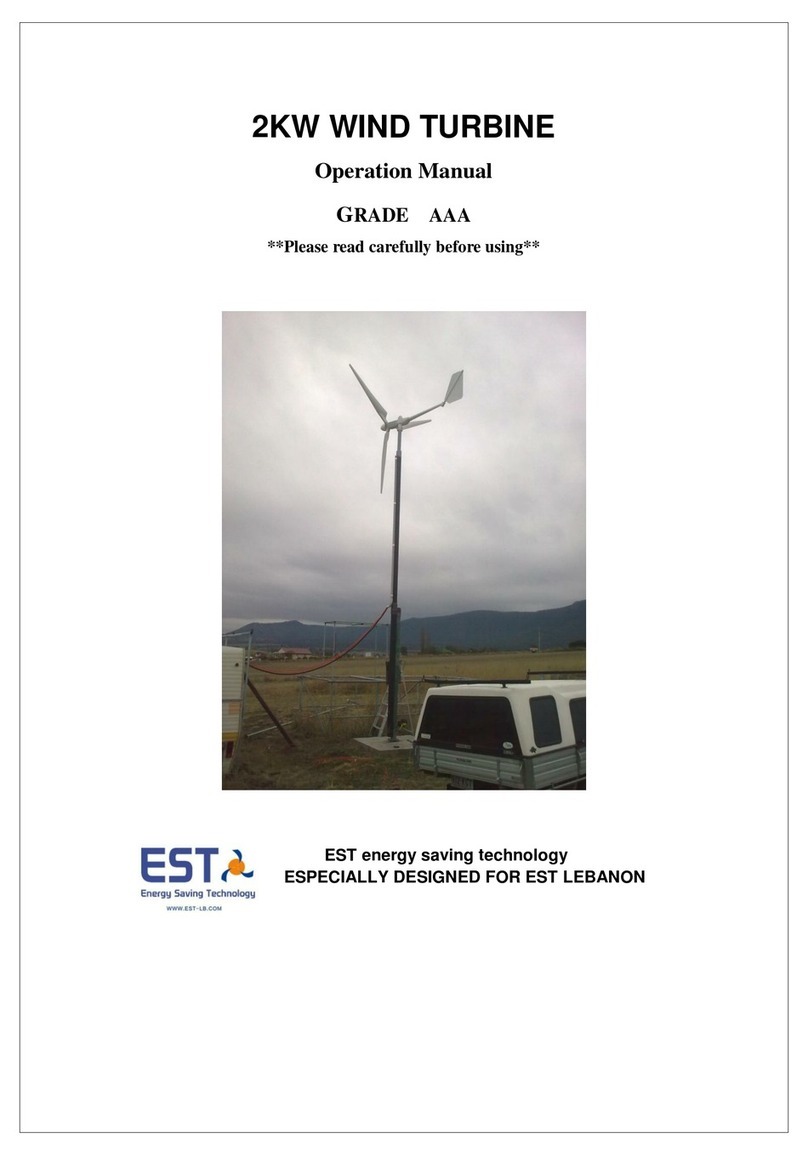
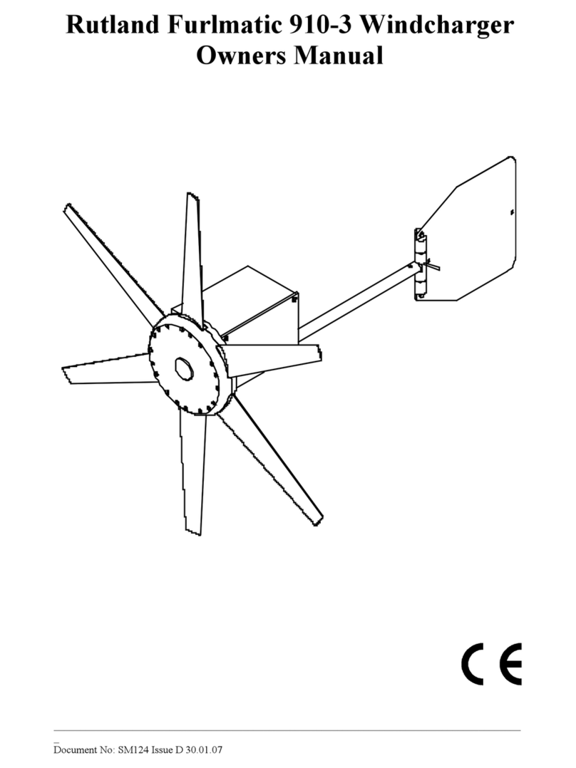
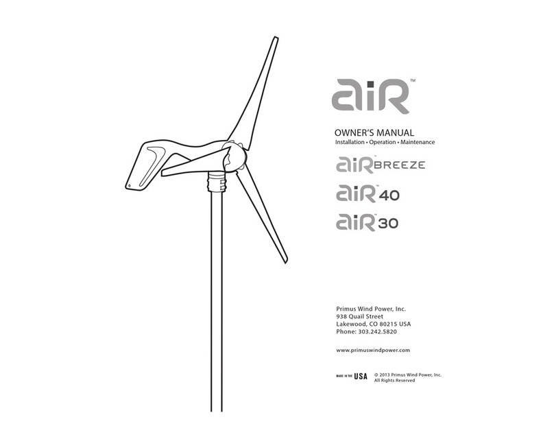
Solazone Q4 User manual

1
Solazone
USER MANUAL
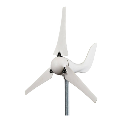
For 300 –600 watt Q4 Model
Vertical Wind Generators
Version 02. Updated 10 June 2017.

2
IMPORTANT NOTE:
Read this manual carefully and completely
before attempting to install or use this device.
Incorrect installation could contribute to death,
injury, or property damage, and will void the
warranty.
Contents
Part 1. Important Safety Information 3
Part 2. Product Features 6
Part 3. Tower and Accessories 6
Part 4. Installation 9
Part 5. Connecting the Controller 12
Part 6. Maintenance and Precautions 16
Part7. Packing List 15
Part8. Warranty 15
Owner’s Registration details 16

3
Part 1. Important Safety Information
For correct installation and use of this equipment, please carefully read
and follow the safety warnings and instructions below.
Basic requirements:
●Do not disassemble the wind generator. Please contact the Solazone
maintenance department for advice whenever the wind generator requires servicing.
●Do not modify or change the equipment structure, safety features and performance
design.
●Obey all local laws and regulations when using this product.
Assembly Requirements:
1. Before assembling the wind generator, or performing maintenance, be sure to read
the user’s manual first.
2. Do not install the wind generator on rainy days, or when the wind scale is at or
above Category 3.
3. After opening the package, immediately short circuit the three leads of the wind
generator until installation. (the exposed copper wires should be screwed together).
4. Before the installing the wind generator, suitable lightning protection must be
prepared. Refer to the appropriate Australian Standards, and make sure the earthing
complies with local regulations.

4
5. When assembling the wind generator, all parts should be fastened with fasteners as
specified in table 2.
Table 2
Serial#
Fasteners
spec
quantity
tightening
torque (N*M)
remarks
Executive
standard
1
Flange bolts
M12x55
4
galvanized
2
Plain washer
D12.2
8
galvanized
3
Spring washer
D12.2
4
galvanized
4
Lock nut
M12
4
≥58
one-time
use
5
Bolts for 3
optional outer
blades
M6x40
18
6
Lock nut for 3
optional outer
blades
M6
18
≥13.6
one-time
use
7
Plain washer
D6.2
36
≥68
one-time
use
8
Spring washer
D6.2
18
6. Before connecting the wind generator flange to the tower flange, connect the three
leads of the wind generator to the three leads of the tower as follows: When using the
hinge method, every pair of wires should be no less than 30mm in length and be wrapped
with Acetate cloth tape for three layers, then sheathed with spun glass paint tube. With
this method, connect the three pairs of wires (attention: the joint of the wires can’t bear the
weight of the tower leads directly, so wires 100mm downward from the joint should be

5
wrapped with adhesive tape and then stuffed into the steel pipe. After that, wind generator
flange and tower flange can be connected.
7. Before hoisting the wind generator, the ends of the output leads, which are to be
connected to the charge controller, should be bared and then screwed together. ( to short
circuit them)
8. During installation, avoid rotating the rotor blades. (The ends of wind generator output
leads must be short-circuited). Only after the installation is complete, and the final
inspection is finished, can the short circuited leads be separated, and connected to the
charge controller and battery, before testing.
IMPORTANT NOTE:
The charge controller must be connected to the battery first,
before being connected to the wind generator. If this
procedure is not strictly followed, any damage or subsequent
failure due to this cause, is not covered by the warranty.

6
Part 2. Product Features
1. This wind generator has low start up speed; high wind energy utilization; beautiful
appearance, and low vibration.
2. It features creative simple design, easy installation, maintenance and repair.
3. The blades are strong with an optimized aerodynamic contour and structure, the blades
have high utilization of wind energy, which contributes to the high annual energy output.
4. The wind generator hss a patented permanent magnet rotor alternator,with a special
kind of stator design that efficiently decreases resistance torque. It makes the wind
generator speed match the generator quite well, and increase its reliability.
Part 3. Tower and Accessories
1. The wind generator flange base is suggested to be installed on a steel pole tower
whose OD is 48mm and wall thickness is 4.5mm.
2. Select the pipe length based on local wind conditions and the geographical
environment.
3, Available tower accessories include (1) the upper tower. (2) The guy wire set. (3) Guy
wire tighteners. (4) Anchor bolts. (5) Line hooks. (6) Tower base. (7) Anti-tarnish,
anticorrosive coating materials.

7
Technical requirement
1、L-type bolts for four galvanized wire strands;
screws should be 60 higher from the mixed earth surface.
2、C25 motar can be used for mixed earth.
mixed earth mounds
Figure1:manufacture of mixed earth mound
Figure2
The manufacture of earth anchor(3 sets)
U-type bolt(4-WIRE STRAND)
Galvanized steel guy wire
Strainer(16 inches)
The earth anchor
Wind turbine tower
GB/T5976-8
1*19-10
3、The metal parts should be under the threatment of
anticorrosion and rust proofing.
Figure3
The manufacture of guy cable
Figure 1 Assembly of anchor, lasso and guy cables
4. The construction diagram, with sizes and dimensions of the upper tower base is shown
in figure 2. It requires solid welding, no leaks at the weld zone; and an earth lug must
be welded on at 20cm above the ground (clearly visible). It must be connected to the
lightening grounding device. (Lightning rod).

8
stiffener
Tron pipe
Flange base
Tron pipe
stiffener
The flange joint
decided on your own
steel bracket
Flange base
welded
tinned
Grounding connector
tinned
Rubber Cushion
Be
米
ugl
Tower base
米
outlet
Figure 2 wind generator flange connection in the top of tower
5. Refer to the Australian Standards, or figure 1 in this manual, to arrange grounding
device.
6. Order any tower parts and accessories according to your requirements.

9
Part 4. Installation
·Do not try to assemble and install the wind generator on rainy days.
1. The three insulated power output transmission wires are installed inside the steel pole
mounting tower. The upper ends come out through the center hole of the wind generator
flange, while the bottom ends come out from a 12mm hole drilled about 30cm above the
ground. The section of wire from the bottom opening to a point which is 60cm beneath
ground should be protected by heavy duty conduit of diameter 17mm to 21mm.
All underground transmission lines to the controller must be correctly installed in heavy
duty orange conduit, buried 600mm deep.
2. The installation sequence of the wind generators can follow the steps as illustrated in
figure 3.
2-1. Place the steel bracket on the ground; block up the flange joint to 1.3m.
2-2. Align the wind generator flange with the tower flange. Cut away insulating layer of
current transmission wire end (which are to be connected with controller) for 10mm,
then short circuit the exposed copper wires (screw them together)
3. The lifting of the wind generator and tower should be undertaken by experienced
personnel, with the presence of a skilled slinger, and all safety procedures being followed.
The tower’s erection should be executed according to the requirements of permanent and
stable construction techniques.

10
4. After completing the installation of the tower and lightning protection, use a 500V
megga to measure the insulation resistance between transmission lines and earth. (earth
wire can act as ground) In the case of not separating the short circuited leads of the
transmission lines, measurement should not be less than 5MΏ, otherwise check whether
the insulating layer may be crushed or damaged, and this should be dealt with
immediately.
Optional Outer Blades Assembly

11
Figure 3
1.Triangle plate for 3 outer blades 2. Inner blades 3. Generator 4. Flange Plate
5. Connecting plate 6. Outer blades 7. Connecting bolts
Figure 4 wind generator decomposition

12
Part 5. Connecting the Controller
·
Avoid heavy rain days for the first commissioning. Ideally, days with gentle
breeze or a strong wind are best. (wind speed: 5~13m/s).
1. Carefully connect the positive and negative poles of the battery to the positive and
negative poles of controller, observing the polarity.
2. Any load circuits connected to the load terminals on the controller should always be
protected by fuses, switches, and plugs.
3. Finally, connect the three current transmission lines from wind generator to the three
wind generator terminals on the controller, in any order. Refer to the controller manual
for more detailed instructions.
4. Battery selection –We recommend using lead-acid, AGM or Gel batteries of the
following sizes: 100 ~ 300 watt wind generators, use 100 ~ 200 Ah battery.
300 ~ 600 watt wind generators, use 200 ~ 400 Ah battery.
5. The controller should be mounted in a dry, well-ventilated place, moisture and
dust-proofed. The inverter case should be kept grounded, and located at least 1.5
metres away from the batteries, to avoid acid gas pollution and fires.
6. The battery should be located in a dry, well-ventilated place, cool in summer, warm in
winter. In such an environment, the battery can be expected to last longer. Protect all
battery terminals from corrosion with covers, or petroleum grease.

13
Attention:
●Battery should be connected to the controller before the wind generator is
connected to the controller.
●Failure to follow these important instructions will void your warranty.
Connection diagram of wind generator, battery & electrical appliances
Note:
Even though this diagram shows solar panels can be connected to the
wind generator controller, we strongly recommend that solar panels be
connected through their own separate solar regulator, unless using a
very small solar array.

14
Part 6. Maintenance and Precautions
1. Wind generators often work in harsh environments, so check it regularly with your
sight and hearing; check whether the tower is swaying or whether the cables may have
become loose. (using a telescope is a good idea).
2. A timely inspection should be made after a heavy storm. If there is any problem, pull
down the tower slowly for maintenance. With regard to wind generators used for
streetlights, an electrician should climb the pole annually to check if there is any problem,
or whether the wind generator has been short circuited, or if security protection measures
should be prepared.
3. Flooded batteries should regularly be checked for fluid level, and even maintenance
free batteries should be kept externally clean, and checked for corrosion on terminals, or
other damage.
4. Do not disassemble the equipment by yourself. Please contact your supplier for
advice when the equipment is out of order.

15
Part 7. Packing List
Serial#
Item
Quantity
Remarks
1
Wind Generator body
1
2
Outer blades
3
optional
3
Bolts and nuts
1 bag
13
L spanner
1
optional
14
hex wrench
1
optional
15
Controller / inverter
1
optional
16
tower
1
optional
Part 8. Warranty
1. The company guarantees customers that the wind generator is of excellent quality,
functions well, the body is complete, and rigorously checked before delivery,
2. We provide one year's warranty for the wind generator, from the date of sale, to the
original purchaser, Damage due to accidents, unauthorized dismantling, or from
seriously violent operation (not according to instructions of use), are not covered by this
warranty.
3. Your sales receipt and these documents serve as the product warranty certificate.
Keep both these documents in a safe place.

16
User information table:
Maintenance records:
Solazone Victoria
68 Highbury Road
Burwood, Vic., 3126
(03) 9808 7337
Solazone Queensland
5 / 6 Beech Street
Marcoola, Qld., 4564
(07) 5448 8304
Sales company:
Owner:
Purchase date:
Address:
Invoice:
Postcode:
Model:
Phone:
Date
Maintenance species
Summary
SMT rework
Table of contents
