EVEREADY Kestrel e400nb User manual

Document No. 1112M001 Revision 1.8 Date: June 2013
1
Kestrel e400nb
250Vdc,
Type 1112-3500-250 (3.5kW 250Vdc)
110Vdc,
Type 1112-3500-110 (3.5kW 110Vdc)
048Vdc,
Type 1112-3500-048 (3.5kW 048Vdc)
With Conditional Two Year Warranty
Important Note: Only the e400nb 3.5kW 250V grid tie version when installed with the Power
One Aurora 3.6 Inverter is MCS and SWCC certified.
Document No. 1112M001 Revision 1.8 Date: June 2013
2
Warranty Registration (Failure to return may render the warranty to be void)
Please complete and return this page within three months after the product delivery date or
within one month following the commissioning date. Attach a picture of your installation
Name of Product: _________________________________
Product Serial Number _________________________________
Pitch Control Serial Number _____________________________
Blade Serial No. (1)_______________ (2)_______________ (3)_____________
Delivery Date____________or Commissioning Date___________
Name and Address of Owner
____________________________________________________________
____________
________________________________________________________________________
________________________________________________________________________
Telephone: ___________________________________________________
___________
Email: ______________________________________________________________
Installation / Site Address (GPS co-ordinates are appreciated)
_____________________________________________________________________
___
________________________________________________________________________
Commissioning Check List
Section
Operation / Procedure
Verified
4.2 All tail assembly M6 fasteners torqued to 10Nm (7.5ft lb)
4.3 Tail boom weld assembly 2 x M12 to 50Nm (36ft lb)
4.3 Tail boom weld assembly 8 x M10 to 50Nm (36ft lb)
4.4 Generator electrical connection secure and insulated
4.4 Generator fitted to the tower 8 x M16 to 120Nm (88ft lb)
4.5 Tail assembly to the boom 2 x M10 to 35Nm (25ft lb)
4.6 Blades properly installed (serial number forward)
4.6 Blade bolts 6 x stainless M16 torqued to 90Nm (65ft lb)
4.8 Nacelle 2 x M6 nuts + 4 x M5 screws stainless to 3Nm (3ft lb)
4.8 Nosecone to stiffener ring 6 x M6 stainless to 4Nm (3ft lb)
4.8 Nosecone to posts 3 x M8 stainless to 10Nm (7.5ft lb)
GENERAL COMMENTS:
………………………………………………………………………………………………………………
………………………………………………………………………………………………………………
Send to: Kestrel Wind Turbines, P.O. Box 3191, North End, Port Elizabeth, 6056, Eastern
Cape, South Africa Or email to: kestrel.admin@eveready.co.za OR Fax: +27 41 394 8183
Type of Tower Installation Engineer Comissioned Date

Document No. 1112M001 Revision 1.8 Date: June 2013
3
Index
1.0 Safety Warnings and Notes 4
1.1 Safety Symbols 5
1.2 Turbine Operating Procedures 6
2.0 The Tower 8
2.1 Mounting Flange and Tower Top 9
3.0 Unpacking the Wind Turbine 10
4.0 Turbine assembly and Installation 12
4.1 Identification Marking 12
4.2 Tail Assembly 13
4.3 Generator to the Tower with Damper Kit 14
4.4 Tail Boom Weld assembly to the Generator 16
4.5 Tail Assembly to the Boom 17
4.6 Blades and Nosecone Stiffener Ring 19
4.7 Mechanical Brake Assembly 20
4.8 Nacelle and Nosecone 23
5.0 Electrical Installation 24
5.1 Lightning Protection 24
5.2 Earthing (Grounding) 25
5.3 Cable Sizes and Installation 25
5.4 Electrical Installation (e400nb 250Vdc and Grid Tie) 27
5.5 Electrical Installation (e400nb 48Vdc and MPPT Charge Control) 28
5.6 Electrical Installation (e400nb 110Vdc, limiter and MPPT) 30
6.0 Installation Commissioning 31
7.0 Maintenance Schedule 32
7.1 Wind Power Class 32
7.2 Planned Maintenance Schedule 33
8.0 Questions and Answers 34
9.0 Technical Specification 35
10.0 Compliance 36
11.0 Warranty 37
12.0 Annexures
Annexure 1 General Information 38
Annexure 2 Choosing a Site 41
Annexure 3 Grid Tie Inverters 43
Annexure 4 Manual Brake Operation 44
Annexure 5 Brake Fitment Instructions 45
Annexure 6 Power One Aurora Settings 54
Revision History
Revision
Date
Comments
Author
1.8 06/13 Add SWCC Logo, technical specification and Annexure 6 J. Carpy
1.7
12/12
Revised technical specification
B.Singh
1.6 11/12 Blade fitment guide improved, brake fitment added J. Carpy
1.5 09/12 MCS Logos added, blade bolts reversed, brake cable turns J. Carpy
1.4
07/12
Add sect. 1.2 Operating procedures, revise main
tenance
J. Carpy

Document No. 1112M001 Revision 1.8 Date: June 2013
4
Disclaimer
Kestrel Wind Turbines makes every effort to give accurate information in this
manual and is in no way liable for any error or omission. The user of this manual
assumes full responsibility and risk
Please carefully read and apply the safety notes. Consult a professional engineer
and take advice if you are unsure.
Note: The Kestrel e400nb has a mechanical brake and the Kestrel e400n is
supplied without this mechanical brake.
1.0 Safety and Warning Notes
Accidents can easily occur and there are always inherent dangers
associated with any type of machine. Tower installations pose their own
dangers. Always work carefully and have an assistant wherever possible.
All installation work should be completed at ground level wherever possible.
Be very aware of the blades during installation. Consult a civil engineer or
reputable builder if you are unsure.
Use caution when working with this wind turbine. Use good handling
methods and take precautions to avoid physical injury. The Kestrel e400nb
output voltage can become dangerous and even lethal when running on
open circuit. Always short the output wires together when the turbine is
disconnected. Do not work on the system when the turbine is running or
when lightning is possible.
Disconnecting any wire may result in a spark. The presence of explosive
hydrogen from battery charging is always a possibility. Adequate ventilation
must be provided for battery installations. Wire sizes must be correct for the
powers supplied. Fire can result from shorts created on a battery. Consult a
qualified electrician if you are unsure.
Slack bolts, poor workmanship and loose electrical connections must be
avoided. The turbine blades are dangerous therefore exercise caution.
Always shut the turbine down before approaching by operating the brake
switch on the controller or the mechanical safety brake. Preventative
maintenance is always the best. Checks are best carried out in calm
weather conditions. Avoid any maintenance or inspection during windy
weather.
Document No. 1112M001 Revision 1.8 Date: June 2013
5
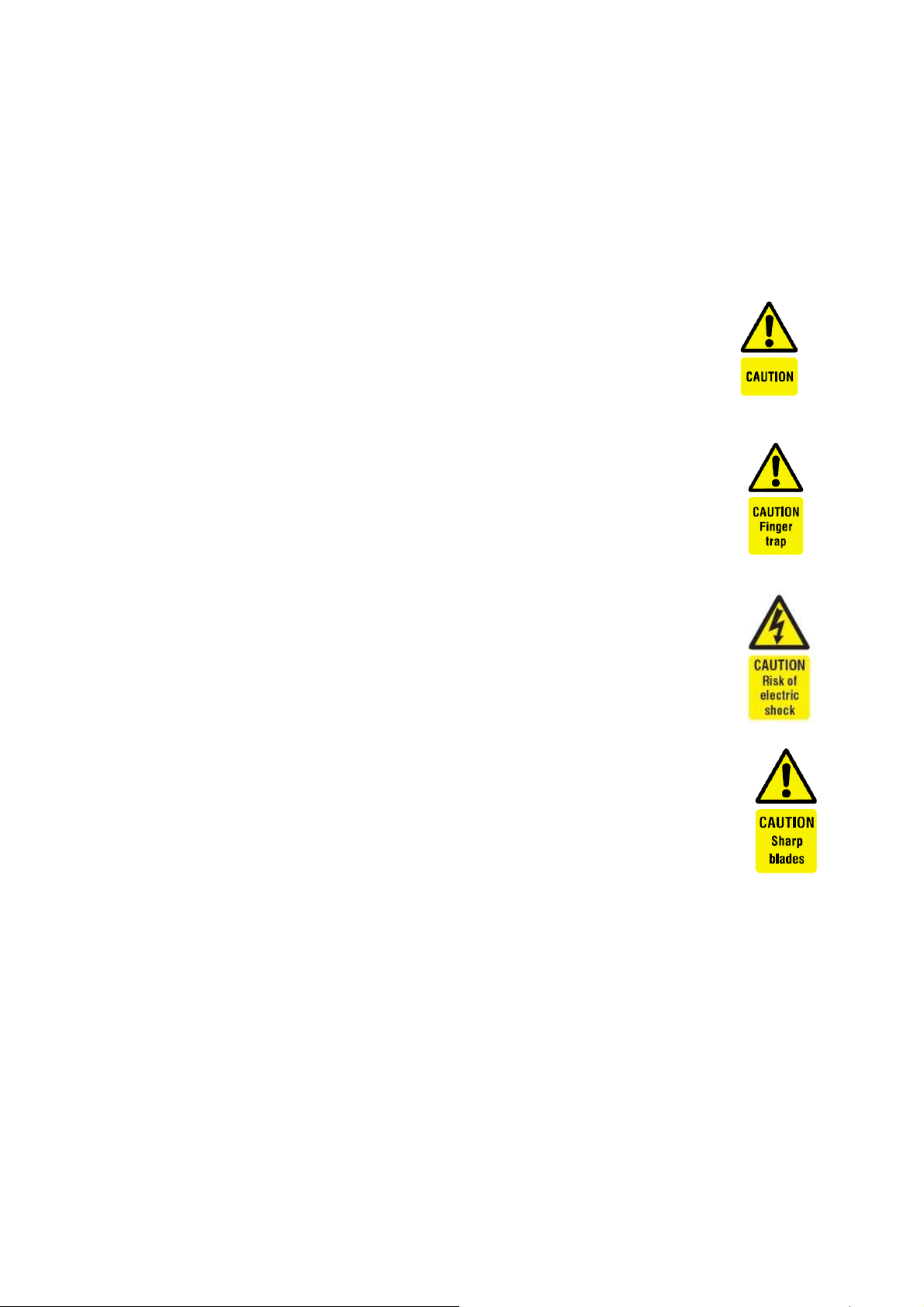
1.1 Safety Symbols
The symbols shown are used throughout this manual to highlight safety
points
General caution warning
Danger of hand injury
Danger of electrical shock
Injury from blades
Work Instructions
Asterisk denotes a special instruction or reminder.
►Arrow head denotes an assembly/build instruction.

Document No. 1112M001 Revision 1.8 Date: June 2013
6
1.2 Turbine Operating Procedures
A standard start and stop procedure is included in this product manual
(Annexure 4). It is recommended that a label showing this procedure be
visible adjacent to the wind turbine tower.
A “T” bar is supplied to operate the tower brake. This “T” bar should be
stored in a safe but accessible location and never left in position on the
tower.
Standard Operating Procedure
This procedure gives a clear action sequence for the following procedures:
i) Procedure for starting and activation
ii) Procedures during normal running
iii) Procedure for stopping and de-activation
iv) Procedure for routine maintenance
Procedure for Starting
(Assumption: The turbine is braked and electrically isolated)
•Ensure that all personnel and animals are well clear of the
turbine tower
•Engage the turbine fuse holder F1/F2 in the interface unit to
connect the turbine.
•Release the electrical brake switch S1 located in the interface
unit
•Approach the tower base and insert the “T” bar into the brake
winch.
•Apply light pressure to the brake and release the ratchet
lever.
•Release the mechanical brake by unwinding the brake winch.
•Observe the turbine to start rotation in the wind.
•Re-apply the ratchet lever and remove the “T” bar.

Document No. 1112M001 Revision 1.8 Date: June 2013
7
Procedures During Normal Running
(Assumption: The turbine is running normally)
•No operating procedures are required. Take every opportunity
to visually observe the system in operation and to listen for
any unusual noise. This is always a good practice.
Procedures for Stopping and De-activation
IMPORTANT NOTE: A stopped turbine will still yaw and align to follow
the wind. A braked machine although stopped, can still cause serious
injury to personnel. The machine must be fully secured before
approaching and must only be approached in calm or very light wind
conditions.
(Assumption: The turbine is to be stopped and electrically isolated)
•Procure the brake “T” bar and approach the tower base.
•Verify that the brake ratchet mechanism is engaged.
•Insert the “T” bar into the brake and wind the handle a little to
verify the ratchet operation.
•While observing the turbine, slowly wind the brake handle until
the brake tension is detected and the turbine slows down to be
stationary.
•Wind the handle two more “clicks” and remove the brake
handle.
•At the interface module, operate the stop switch S1 and pull
out (disengage) the turbine fuses F1/F2.
Procedures for Routine Maintenance
Routine maintenance is described is Section 7.0 of this manual. The
same start and stop procedures are used for maintenance.
The tower brake “T” bar must be removed to prevent accidental brake
release and to “Lock out” the turbine brake.
Document No. 1112M001 Revision 1.8 Date: June 2013
8
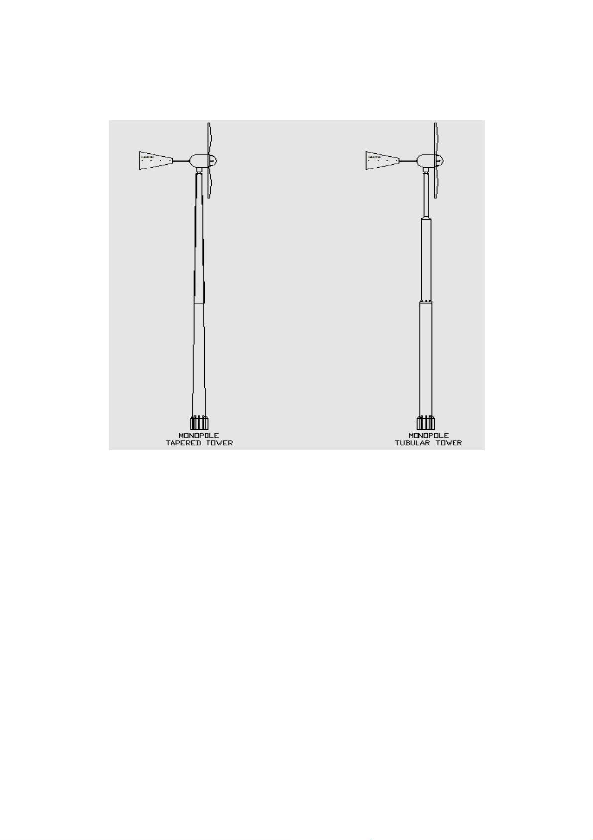
2.0 The Tower
A monopole free standing tower is preferred for the Kestrel e400nb.
The tower sections can be taper formed or parallel tubular. These
towers use larger diameter sections to increase rigidity and strength
but optimise the total tower weight. This tower type is also the easiest
to assemble and install due to its simple design and optional hydraulic
or electro-mechanical lifting pack.
Monopole towers are usually available in 12m (40’) and 18m (60’)
versions. Consult the factory for higher options.
Other acceptable tower types include lattice construction and tripod
towers. Guyed towers are preferred when much greater heights are
desired. Although Kestrel only supplies standard approved towers, the
turbine characteristics and parameters for tower design are available
from the factory.
Document No. 1112M001 Revision 1.8 Date: June 2013
9
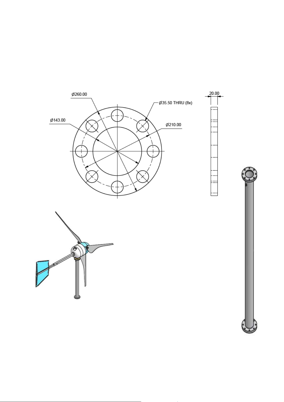
2.1 Mounting Flange and Tower Top
The tower for the Kestrel e400nb is fitted with a circular flange made
from 20mm 300WA mild steel. The dimensions are shown below.
The following specification is
recommended for the top pipe
section of the tower. Mild steel
pipe grade 350WA Nom. Dia
125mm (5.5”) SCH 40 by 1.8m
long
A standard adapter pipe is
available from Kestrel where the
turbine will be fitted to an
alternative structure. The pole
includes a securing point for the
tower cable. Consult your dealer
for more details.
Document No. 1112M001 Revision 1.8 Date: June 2013
10
3.0 Unpacking the Wind Turbine
A Packing list is packed with the product. Ensure that all parts are
present. Notify your dealer of any shortages.
The e400nb is contained in one shipping crate. Check the crate for any
transit damage and then carefully remove the top of the crate to reveal
the contents. Check that everything is intact. Pay special attention to
the blade package. Carefully remove all the parts for safe storage. The
last item to be removed is the generator assembly, which is fully
secured to the packing case base.
IMPORTANT NOTE:
Do not lift or maneuver the generator
USING THE NOSE CONE PILLARS.
This will damage the pillars and cause
unbalance.
Document No. 1112M001 Revision 1.8 Date: June 2013
11
The bare generator and pitch control is factory assembled. This
complete sub-assembly weighs approximately 170kg (375lb).
Unpack and check the following parts. Inform your supplier of any
defects or shortages.
►Remove the blade package and store
safely.
►Remove the nacelle and nosecone with
ring and store safely.
►Remove the two boom sections.
►Remove the two tail plates.
►Remove any other accessories that were
shipped for you.
►Locate and remove the fastener pack
(assembly grease inc.).
►Remove the complete generator assembly.
Note: The fasteners are supplied in marked packs. Each pack
contains a set of fasteners for different parts of the turbine. The
enclosed grease is used on all nuts that are M10 or larger.
Note: One additional fastener pack contains one spare unit of every
fastener used on the turbine.
It may be useful to remove the sides of the packing case to access the
assembly. Remove the securing bolts and pads to free the generator
assembly. If possible, use lifting gear to remove the assembly from the
case. Otherwise have at least three other assistants to lift the
assembly from the case. Two lifting straps may be fitted to the
generator for lifting. Beware of the generator tipping forward and
causing injury to hands.
Beware not to damage the output cables below the generator. The
generator assembly is heavy at the front and will easily tip over. When
installed, the turbine is balanced on the yaw shaft.
Document No. 1112M001 Revision 1.8 Date: June 2013
12
4.0 Turbine Assembly and Installation
You will need the following hand tools.
►Trestle, table or other support to support the turbine that is safe for
250kg (550lbs).
►Plastic or rubber mallet, brass mallet/ hammer & 8mm pin punch.
►Full set of ring spanners from 10mm – 24mm.
►Metric socket wrench set.
►Set of standard screwdrivers (plain and Philips).
►Torque wrench suitable for torques of 0 – 180Nm (132ft lb).
►Electrical pliers, cutters & crimping tool.
Refer to the diagrams and follow the instructions to assemble the
complete wind turbine.
This manual assumes that the support tower is already installed and
lowered to ground level ready for turbine installation.
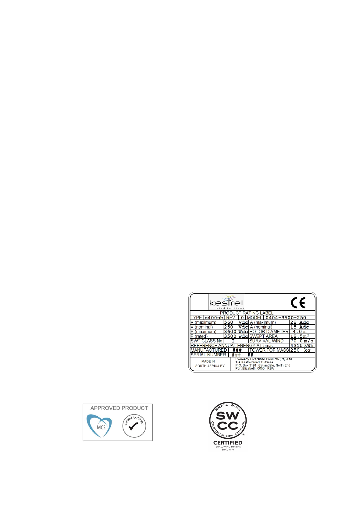
4.1 Identification Marking
The turbine is fitted with a rating
label similar to the image.
Note down your turbine serial
number for future reference!
Note: Only the e400nb 3.5kW 250V version has MCS or SWCC Labels

Document No. 1112M001 Revision 1.8 Date: June 2013
13
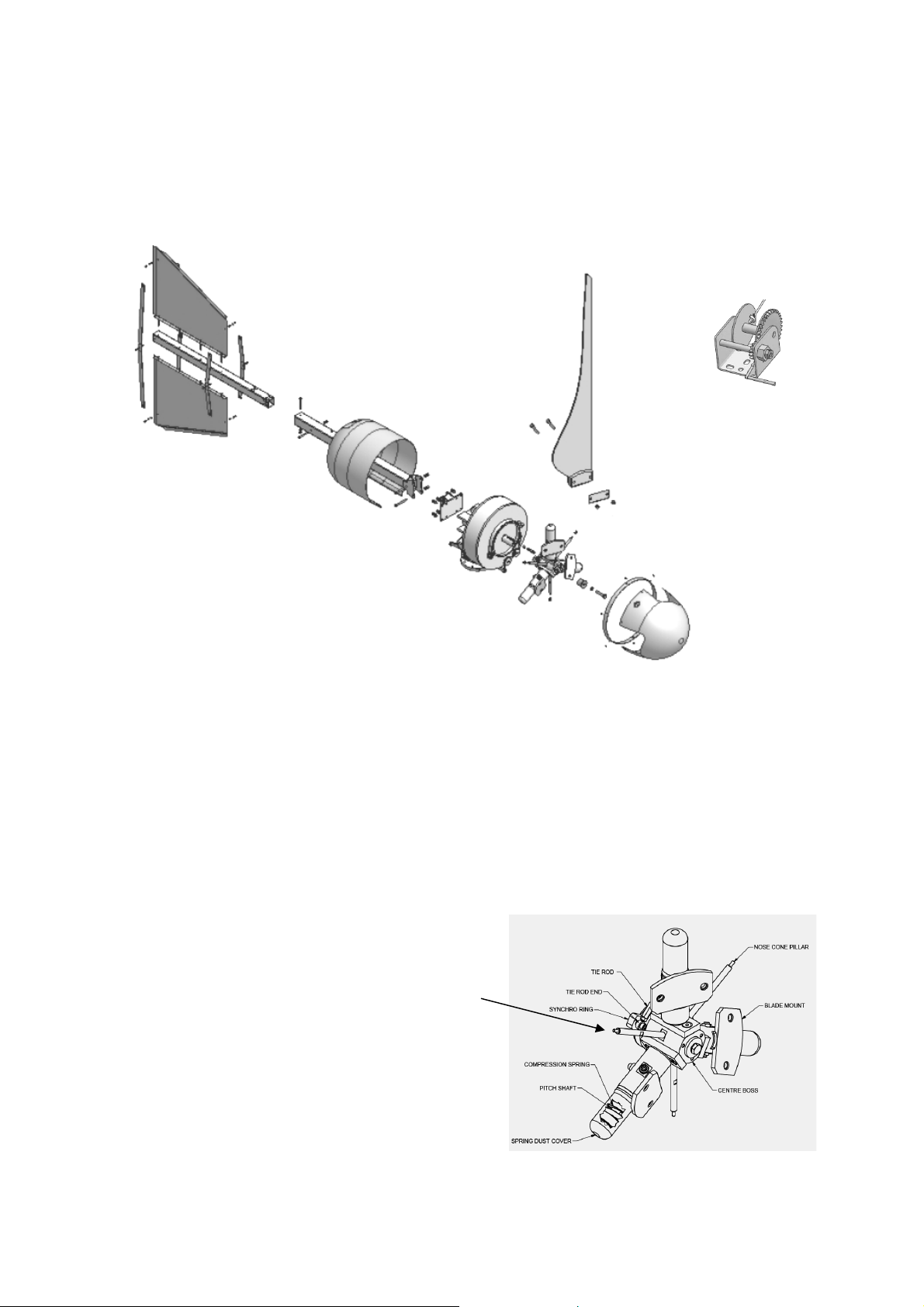
4.2 Tail Assembly
ASSEMBLE EXACTLY AS SHOWN IN THE DIAGRAM. FIT ALL THE
FASTENERS BEFORE TIGHTENING.
The tails will be in the middle line of the boom
You need the fastener pack marked “Tail Assembly” for this work.
►Top (2) and bottom (3) tail plate to boom (1) with four off stainless
bolt sets (6). Nuts and washers on the bottom.
►Two rear stiffeners (4) to boom (1) with one stainless bolt set (6).
►Two front stiffeners (5) to boom (1) with one stainless bolt set (6).
►Bolt all stiffeners (4) and (5) to top and bottom tail plates (2) and
(3) with four off bolt set (7).
►All tail fasteners are M6. Torque all fitted bolts to 10Nm (7.5ft lb).
PARTS LIST
ITEM
QTY
DESCRIPTION
1 1 Tail Boom Extension
2 1 Top Tail Plate
3 1 Bottom Tail Plate
4 2 Rear Stiffener
5 2 Front Stiffener
6 6 Hex Bolt M6 x 80 long, washer and nut
7 4 Hex Bolt M6 x 16, washer and nut

Document No. 1112M001 Revision 1.8 Date: June 2013
14
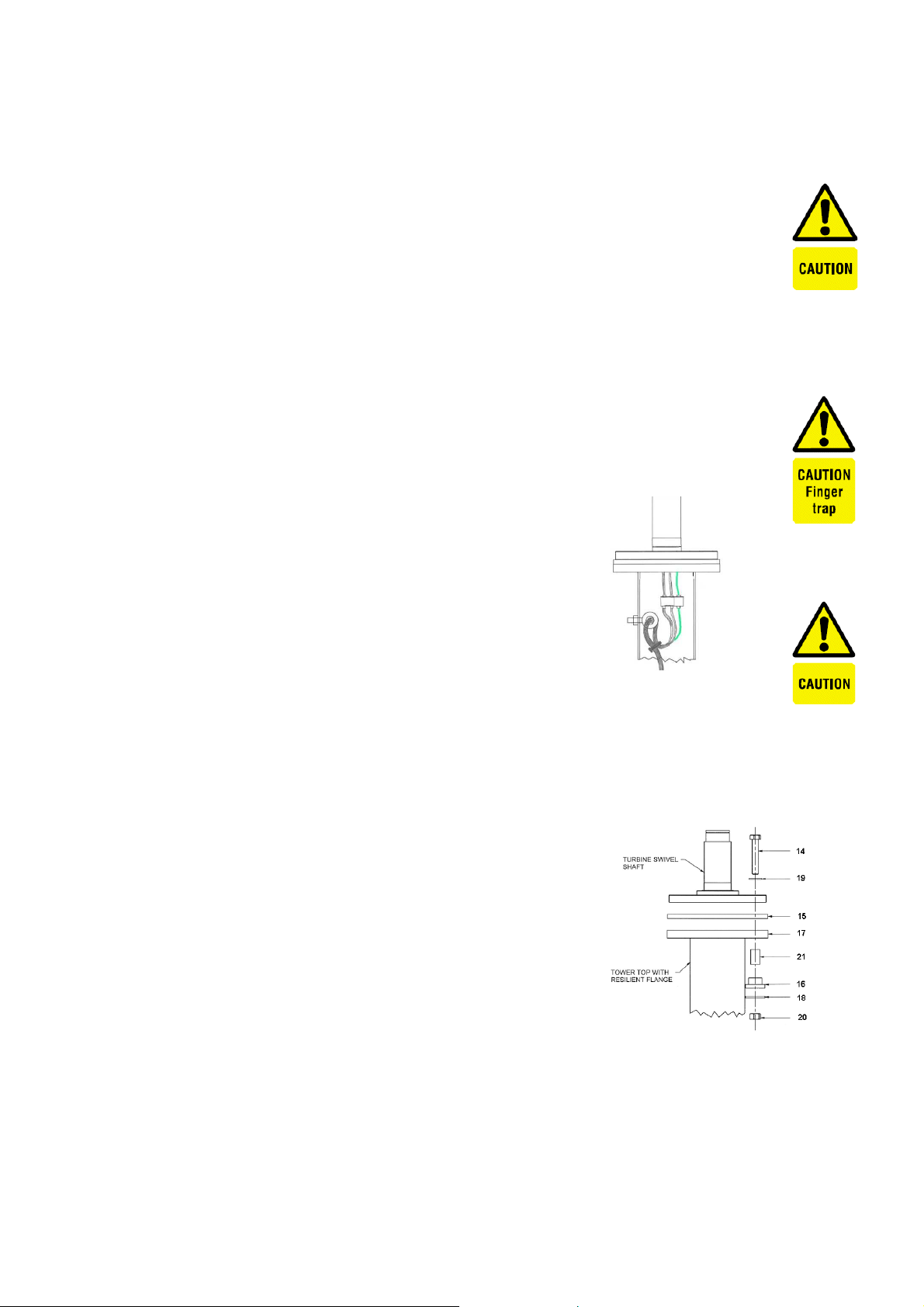
4.3 Generator to the Tower with damper kit
The steel flange (17) is fitted and welded to the tower top to adapt
non-Kestrel towers. Kestrel accepts no responsibility for any third
party tower design or application.
Each e400nb turbine is supplied with a standard rubber mounted
resilient kit. The purpose of the kit is to eliminate generator acoustical
noise being transferred down the length of the tower. The kit consists
of the following components:
PARTS LIST
ITEM
QTY
DESCRIPTION
14 8 Hex Bolt M16 x 90 H.T 8.8 ZP
15 1 Rubber flange
16 8 Rubber sleeve
17 1 Steel Flange (for welding to tower)
18 8 Fender washer
19 8 16mm standard washer
20 8 M16 Hex Nut
21 8 Compression sleeve
Take note that the damper kit includes a steel resilient flange (17)
that must be welded to third party towers and surface treated
before turbine installation.
The already installed tower is lowered to ground level before
mounting the generator. The power cable is also fitted.
Secure the tower cable at the top of the tower. The tower cable
must not hang or pull on the generator cables. Leave enough
tower cable to make the connection to the generator.
Do not “spin” the generator by hand. Short the red (+ve) and
black (-ve) generator output cables until wiring is to be done.
Document No. 1112M001 Revision 1.8 Date: June 2013
15
Avoid damage to any paint finishes by protecting with suitable
sundry material (HD foam, carpet tiles, cloth rags etc).
Make all power cables ends safe by insulation before installing
the generator.
►Support the lowered tower at a suitable height to receive the
generator. Be sure that the support can bear the total weight
after the generator is mounted. Allow for 250kg (550lbs).
►Support the generator at a similar height with the mounting
flange in line with the tower flange. Allow for 250kg (550lbs)
Observe polarity on electrical connections.
Connect +ve (red) and –ve (black) generator
output cables correctly. Reverse polarity will
damage the generator and any connected
equipment.
►Remove the short across the generator
wires. Make and complete the electrical
connection between the generator and the tower cable. The
250Vdc generator can output up to 550Vdc when unloaded.
The 48Vdc generator can deliver up to 80A.Use properly rated
connectors and ensure that this connection is good and secure and
completely watertight. The generator earth wire
is connected and extended down to the
ground earth for the tower.
►Fit the generator to the tower while storing the
cable and connector down the inside of the
tower. Fit the resilient kit in the order as
shown above. Ensure that no cable is
damaged during this operation
►. Torque the flange bolts to 120Nm (88ft lbs).
Document No. 1112M001 Revision 1.8 Date: June 2013
16
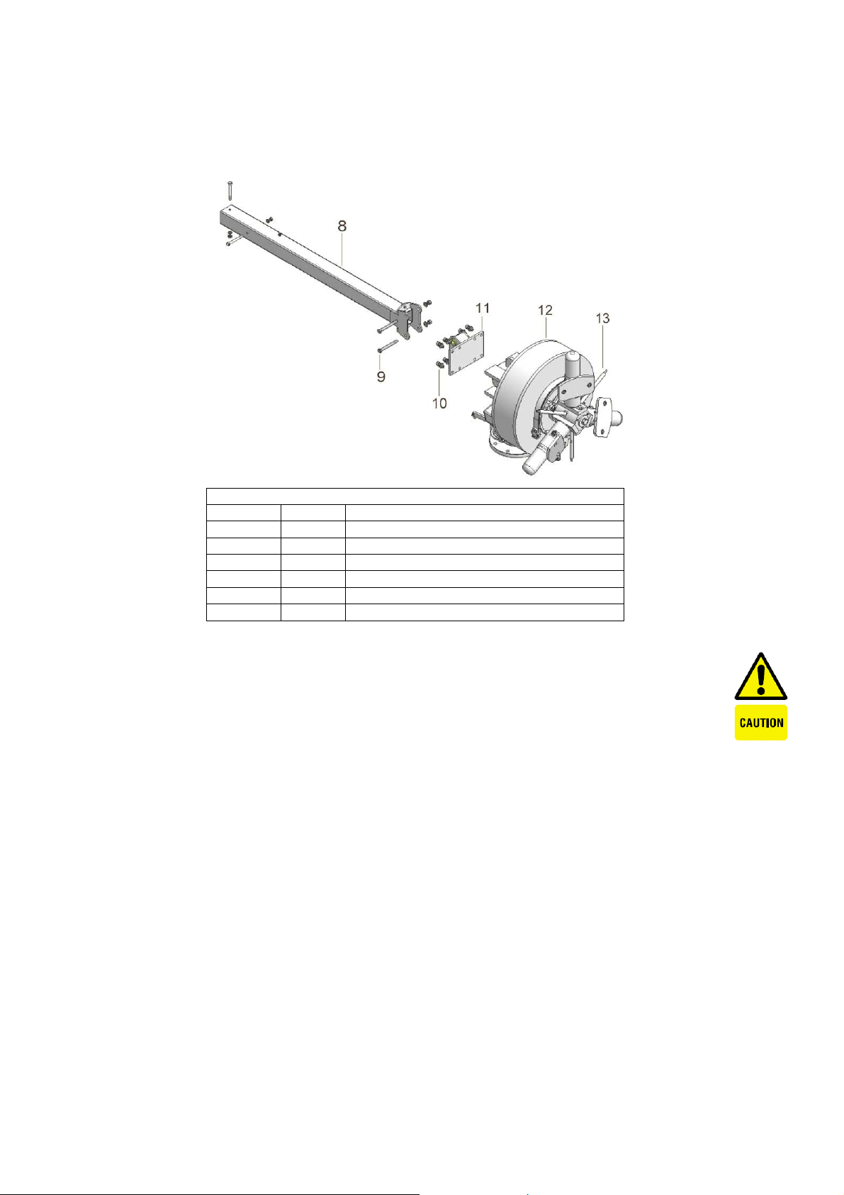
4.4 Tail Boom Weld Assembly to the Generator
PARTS LIST
ITEM
QTY
DESCRIPTION
8 1 Tail Boom Weld Assembly
9 2 M12 Tail Boom Bolt, washer and nut
10 8 M12 Allen cap bolts and washers
11 1 Tail Boom Flange
12 1 Generator
13 1 Pitch Control
THE GENERATOR SHOULD BE FITTED ON THE TOWER
BEFORE FITTING THE BOOM ASSEMBLY TO THE
GENERATOR.
FIT ALL THE FASTENERS BEFORE TIGHTENING AND
ASSEMBLE EXACTLY AS SHOWN IN THE DIAGRAM.
Take note of the “this way up” orientation indicators on each
component.
You need the fastener pack marked “Tail Boom weld Assembly” for
this work.
►Fit the flange weld assembly (11) with yellow bushes to the rear
end of the generator (12) using the 8 M12 bolt sets (10). Torque to
50Nm (36ft lb)
►Fit the boom (8) to the flange weld assembly (11) using the 2 M12
bolt sets (9). Torque to 50Nm (36ft lb).
►Store the remaining fasteners for later use.

Document No. 1112M001 Revision 1.8 Date: June 2013
17
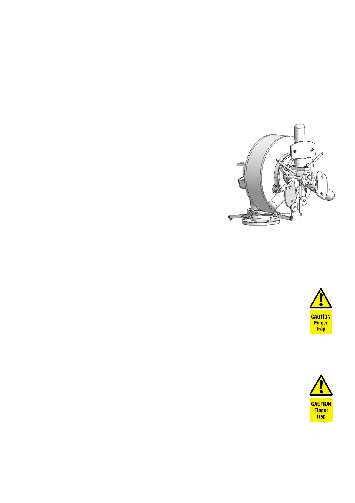
The finished generator installation is shown below
4.5 Tail Assembly to the Boom
PARTS LIST
ITEM
QTY
DESCRIPTION
22 2 Hex Bolt M10 x 90, washer and nut
23 1 e400nb Nacelle
24 1 Complete tail assembly
You need the fastener pack marked “Tail Boom weld Assembly” for
this work.
Slide the nacelle over the boom weld assembly before fitting the
tail assembly !!

Document No. 1112M001 Revision 1.8 Date: June 2013
18
►Slide the tail assembly (24) to the boom as shown. Place a little
grease inside the two nut threads. Fit the two stainless M10 bolt
sets (22). Torque to 35Nm (25ft lb).
►Raise the tower and generator to a suitable height from the ground
for blade fitment.

Document No. 1112M001 Revision 1.8 Date: June 2013
19
4.6 Blades and Nosecone Stiffener Ring
You need the fastener pack marked “Blade Fasteners” for this work.
Fit the Nosecone stiffener ring (29) over the pitch control
before fitting the blades (25) and leave it loose in place !! The ring is
tapered and the smaller diameter must face forward to match the
shape of the nosecone. The ring is later bolted inside the nosecone.
Each blade is fitted with 2 steel positioning sleeves. The protruding
end of each sleeve must locate in the recessed hole on the blade
mount.
►Insert the two bolts (28) from the rear, through the blade mount and
push them through to the front.
►Offer the first blade (25) to the blade mount and slide the blade
over the two fixing bolts. The blade serial number must face
forward and be visible from the front.
►Fit the compression plate (27) on to the blade and protruding bolts.
PARTS LIST
ITEM
QTY
DESCRIPTION
25 3 Blade
26 6 Hex Nut M16 Nylock
27
3
Compression plate
28 6 Hex Bolt M16 x 100
29 1 Nose Cone stiffener ring
Document No. 1112M001 Revision 1.8 Date: June 2013
20
Stainless nuts can sieze on the bolt. Put a little waterproof
grease inside the stainless nut before fitting.
►Fit the two M16 nylock nuts (26). Tighten to 90Nm (65ft lb)
►Repeat the fitment for the two other blades.
Note that no balancing procedure of the turbine blades is required.
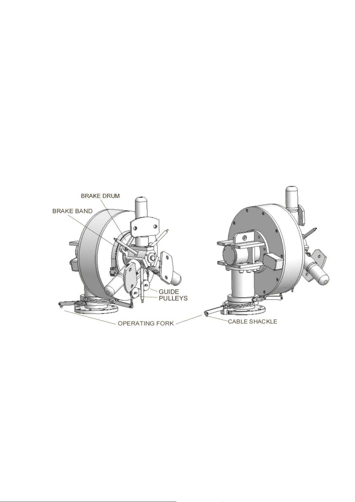
4.7 Mechanical Brake Assembly (e400nb only)
The Kestrel e400nb is fitted with a mechanical band brake. This brake
is activated by a manual cable winch and a drop cable that are shipped
with the turbine. A “T” bar is also included that is inserted into the tower
to operate the winch.
The brake mechanism is a factory fitted assembly and is operated by
one singular drop cable. No adjustment is required to the brake
mechanism on the generator assembly.
This manual suits for next models
3
Table of contents
Popular Wind Turbine manuals by other brands

Superwind
Superwind 1250 Operation manual

Tumo-Int
Tumo-Int 3000W 5 Blades Wind Turbine user manual

Bergey
Bergey 24 VDC B owner's manual

Leading Edge
Leading Edge LE-v50 Installation & operation guide

ista Breeze
ista Breeze i-1500 Windsafe Translation of the original instructions

Enair
Enair E70PRO user manual

Guang Mang
Guang Mang EW200 user manual

Primus Wind Power
Primus Wind Power Air X owner's manual

Missouri Wind and Solar
Missouri Wind and Solar Freedom manual

Automaxx
Automaxx 400 Watt Turbine user manual

Spreco
Spreco SHARKY User and installation guide

Nature's Generator
Nature's Generator Powerhouse Wind Turbine user manual