EST 2KW WIND TURBINE User manual

2KW WIND TURBINE
Operation Manual
GRADE AAA
**Please read carefully before using**
EST energy saving technology
ESPECIALLY DESIGNED FOR EST LEBANON

1. Application
Awind power generator is a piece of equipment that converts wind energy into electric power
which is used to charge a storage battery group. It can be widely used in windy areas without
electrical grid access. It is capable of providing power for lighting, TV, telecommunication
equipment and other equipment.
2. Structure and Main performance
The unit is mainly composed of wind rotor, permanent magnet generator, tail vane, stand,
electronic controller, storage batteries, electric inverter, electric cable, and diversion load
(Fig1)
Main technical performances
Rotor Diameter (m)
3.2
Material and number of the blades
Reinforced fiberglass *3
Rated power/maximum power
2000/3000
Rated wind speed (m/s)
10
Startup wind speed (m/s)
3
Working wind speed (m/s)
3–30
Survived wind speed
40
Working voltage
DC48v
Generator style
Three phase, permanent magnet
Charging method
Constant voltage current saving
Speed regulation method
Yawing + Electromagnetic brake
Stop method
Manual brake
Tower height (m)
6
Weight (kg)(not including batteries
or inverter)
Main unit 95 / Total 155
3. Preparation
3.1 Prepare batteries according to manufacturers specifications.
3.2 Unpack and check the turbine parts and verify all parts are included.
3.3 Choose an open and flat place with no barriers around for wind turbine installation.
To avoid losses due to voltage drop over the cable run, the distance between wind turbine
and batteries should be made as short as possible. For best results, it should be less than
30m.
3.4 Install Foundation pylon and anchor points.
3.41 Dig a hole where you want the center pylon for the turbine base. The size of the pylon
should be 50X30X36cm. Next dig four triangular (each side is 80cm) pits with the depth of
60cm symmetrical 4.5 meters from the central hole in four directions. One point of each

triangle pit points to the center hole. (Fig 2)
3.42 Start with the center pylon. Attach the 4 foundation bolts onto the base plate. Screw on the
M16 nuts respectively until the top of bolt is 15mm out of nut. Align the axis of the pivot pin
with anchor points BD or AC. The Base plate should be 4-5cm above the ground. Adjust the
base plate to make it level and fill the hole with concrete. The mixture ratio of concrete is
cement: sand: gravel= 1:2:3.
3.43 Hold the top of the anchor chain and put the anchor horizontally into the base of pit along
the outside edge. Lay crushed stone (about 2~5kg) into the pits, then cover them in
concrete. Lay crushed stone into the pits and add more concrete. Repeat until the triangular
pit is full. Finally adjust the guy wire anchors toward the center with an angle of 60-degree
from the ground. Hold the chain and fill the pit with concrete until the middle part of the top
link, leaving the other half out of the concrete. (Fig 3)
3.44 The curing period of the concrete pylons and anchors is 100 hours. During this period, do
not install the wind turbine.
4. Installation procedure
4.1 Select a sunny day without wind (wind speed less than 3m/s)
4.2 Adjust the Base plate level, then put the washer onto the foundation bolt and fasten the nuts.
Put together the upper, middle and lower mast. Lay the mast on the “A” pit. Link the mast
bottom to the base plate with Φ16 pin, then put on the washer and connect them with the
pivot pin.
4.3 Draw out the guy wires in all four directions. Bend the tip of the steel wire to a loop, the
length of which should be approximately 20cm. Put the loop for guy wire through the loop
welded to the tower section. Close the loop with two wire-clamps. Repeat for each of the
remaining cables.
4.4 Put the heart ringer for steel wire across the “o” loop of turnbuckle, and then rip the steel wire
into the heart ringer. Bend for a loop; no less than 30cm long, fasten with wire-clamps. Hook
the turnbuckles ofA, B and D pits to the chain of anchor. Draw back the mast, and then hook
the turnbuckle and anchor chain. Adjust the length of steel wire through turnbuckles to plumb
the mast. Install the stay bar to the lower mast,fix up it with M12 bolts. Untie “U” shape
screw between anchor and turnbuckle of pit C. Connect the steel wire of C pit and the top of
stay bar and fasten it. Then adjust until the steel wire between stay bar and mast in strain
state.
4.5 Put a 1m bracket into pit A. Loose the “U” shape screw buckle in pit B and pit D (About 5cm
length). Untie the link of the “U” shape screw and the ground anchor chain in pit C. Fall
down the mast slowly; support the steel wire pothook with20cm height stow-wood.
4.6 Insert the cable through the bottom to the top of the mast with a steel wire(2~3mm) and
extend out about 20 to 50cm. Connect the 3 ends of the cables (which start from the slip
ring) with the terminal block. Connect the 3 ends of the cables which come from the slip ring
with the terminal block.
4.7 Install the generator onto the mast top through the sleeve. Fasten the screw.
4.8 Assemble the tail rod to the rotating body, aligning the M12 holes correctly, insert the lock
washer; screw the four M12X25 inner six angle nuts tightly. (FIG5)
4.9 There are two holes that can be chosen on the trough shape clamp of the tail rod and two
holes distributing on the two sides of the tail vane tie-in’s axes, whose diameter is 11mm.

Insert the tie-in of tail vane into the trough shape clamp of the tail rod, insert M12X70 bolt
into the ø13 holes correctly, put on washer 12, lock washer 12 and M12 self-locking nuts,
Adjust the tail rod angle against the level plane according to the local wind resources and
electricity consumptions (it can be adjusted to four angles). Decrease the angle can
increase the rotating speed of the rotor. Then insert the screw shaft into ø13, screw the
adjusting bolt and nut (M12). After adjusting, tighten the two self-locking nuts.(See fig.6).
4.10 Before leaving the factory, every rotor has been assembled and balanced. For easy
transportation, the rotor had been disassembled. When reassembling the rotor, please
check the marks on the blades, to return them to the proper positions, then fit the M12×80
screws, washers, and M12 self-locking nuts one by one. Tighten the nuts finger tight first,
then measuring the distances between the center point to the tip end of blades a, b and c,
the difference in distance between the 3 blades should less than 5mm. If it is not, adjust the
blade before tightening the bolts. Tighten the nuts firmly to a torque of between 40 –45 N.m
(see fig.7).
4.11 Assemble the blade-rotor on the axes of generator, put on the flat washer and lock washer
one by one, and then screw the self-locking nut tightly.
4.12 Assemble the nose cone to the rotor hub with M6 screws, lock washers and flat washers.
4.13 Draw backs the mast through chain jack; connect the screw buckle of pit C to the anchor.
Adjust the length of the screw buckle in four directions. Strain the steel wires to make the
mast in its vertical position. Strain the steel wire until it can rebound lightly when gives a
transverse force.
4.14 Check the wire block, screw buckle and all connecting point. Make sure it is safe. Then
wrap and blocked them with galvanized wire. Put anti-corrosive grease on wire block,
screw buckle and all links where necessary.
4.15 Connect the batteries in series to be a group, two ends connectors are “+” pole and “- ” pole
respectively. Connecting wire between batteries and the input & out put wires of the battery
group should be 6mm², “+”pole is marked by red color; and “-”pole is marked by black(or
yellow, or blue). All connections should use wire connecting clips to ensure every
connection is secure and electricity conducts well. In order to prevent corrosion of the
connecting clips caused by acid vapor from the batteries, put a layer of protective grease
on them.
4.16 Connect the red wire “+” pole of the batteries to the “+” pole connector of the controller &
Inverter; then, connect the black wire of “-” pole of the batteries to the “-” pole connector of
the controller & Inverter. Connectors must be tightened firmly to ensure good electrical
conductivity.
4.17 Connect the 3 phase output wires of the generator to the connectors of the controller
respectively.
4.18 According to the different requirement, there are two kinds of arrangements for
electric box: a) DC output; b) DC/AC output. Please follow the marks on the box to connect
with the appliances. Please take care for safe operation when using the AC220 output!
5. Application notice
5.1 Application principles
5.1.1 Please read the specification carefully before using. Do not install or uninstall on a windy
day.
5.1.2 The off-grid wind turbine charges the batteries through a controller or a control-inverter.

When there is no wind, it consumes the electricity from the battery group. Therefore, after
discharging, the batteries should be recharged soon, especially for lead-acid batteries. If
the batteries cannot be recharged quickly after over discharging, the working life of the
batteries will be reduced. The users should regulate the consumption of electricity
according to local wind conditions and the output of the wind generator, or have alternative
charging methods available.
5.1.3 After passing full wave bridge rectification, the 3-phase AC electricity generated by the
wind generator will output in DC24V, 36V, 48V, or 120V DC to charge the battery group.
The voltage of the battery group should be equal to the DC voltage of the wind generator
(after rectification), so the system works at its full efficiency. The input DC voltage of a
matched inverter should be equal to the working voltage of the wind turbine.
5.1.4 The input DC voltage of the matched inverter should be equal with working voltage of the
wind generator (after rectification).
5.2 Safety Notes
5.2.1 Do not run the wind generator without any load, or run at a very high rotating speed for
long periods of time.
5.2.2 Check the tower condition regularly. If there are any loose components, they should be
tightened immediately, to prevent the wind turbine falling down.
5.2.3 When running speed of the rotor is high, people should not stay under the wind turbine.
5.2.4 When wind speed is more than 24 m/s, the wind turbine should be stopped manually.
5.2.5 When vibration or strange noise is heard while the turbine is working, stop the wind turbine
and find the reason to prevent damage.
5.2.6 The power supply line of the wind generator should be run independently. It can not be
mixed used with other power supply lines. DC power supply is safer and more efficient for
lights. For home electric appliances, an AC power supply line (from an inverter) should
be used. It is suggested that the connector of a refrigerator should be inserted in a special
plug with a timer to control its usage.
5.2.7. When connecting the wires of the wind generating system, the battery lines must be
connected to the controller & inverter box first, then connect the three lines from the
generator to the controller. When disconnecting the wire from the wind generating
system, the three generator lines must be first disconnected from the controller, then
disconnect the two lines of the battery group from the controller & inverter box.
5.2.8 The “RUN & STOP” switch on the controller & inverter box should keep at the “RUN”
position under normal conditions. Only toggle the switch to the “STOP” position when the
batteries have been fully charged or to protect the system against storm winds,. It is not
recommended to move the switch when wind is strong and rotor is rotating at high speed.
Only change the switch to the “STOP” position when rotor is rotating slowly.
5.2.9. The batteries should be installed in a place that is far from fire and heat sources. The gas
generated from the charging and discharging process should be vented from the room.
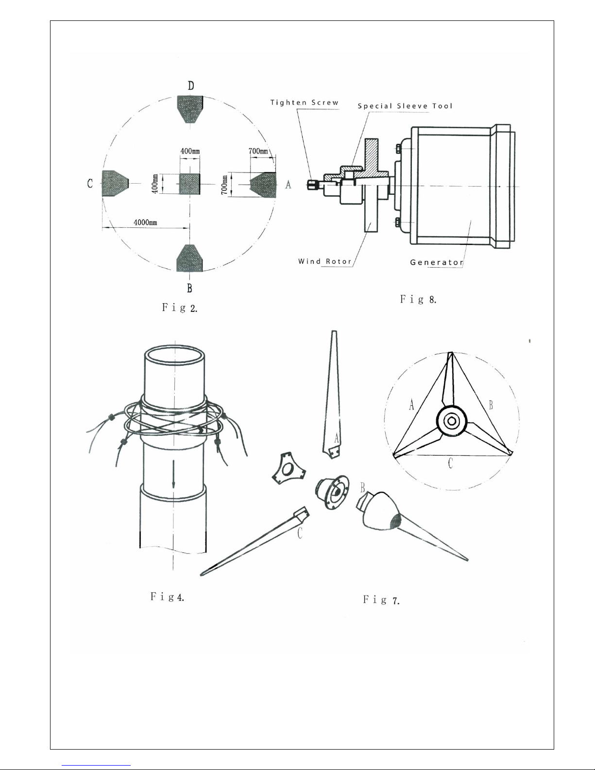
5.3.Keep the rotor balanced, eliminate vibrations
If the blades lose balance due to outside damage and create strong vibrations, the wind
generator must be stopped until the trouble is eliminated. The attached special tools should
be used for disassembling the rotor. Remove the nut and washer from the axes end of
generator first, screw the special sleeve onto the hub firmly, then drive the M16×30 screw

into the sleeve to remove the rotor from the shaft of the generator(see fig.8). After repairing
the imbalance, reassemble. Torque should less than 0.02N.m.
6. Maintenance of the wind generator
The products are divided into two types: common product and high quality product (no
maintenance). The common product needs the following maintenance regularly:
6.1. Check, clean and lubricate all rotating parts once per year.
6.2 Before rainy season or winter depending on climate, clean outside and paint anti-rust grease
on all fixed connecting cables and tower parts once a year.
6.3 Lubricate and maintain bearing of generator once per operating year.
6.4. Clean, remove rust and paint all exposed parts once every two years.
The maintenance of high quality product (AAA)
a. Exposed parts are made of stainless steel and have been treated by special long life
rust-protection treatment, so the outside of those parts do not need maintenance.
b. The generator has high grade bearings and high grade lithium grease. The bearings need to
be checked after operating for 5 years. If it is necessary, add some lithium grease to the
bearings.
6.5 Inspect ground rod connection to the turbine mast to ensure the wire is still in place and
secure.
7. Troubleshooting
The wind generator is designed and manufactured to be trouble-free and low-maintenance. If
the installation and operation are correct, failures will not appear under normal conditions. In
case of failure, please consult following table.
Trouble
Reason
Solution
Wind generator
vibrating strongly
1. Steel cable guy line is loose.
2. Hub blade bolts are loose.
3. Blade is defective caused by
outside force.
4. Ices over on the surface of blades,
causes imbalance.
1. Tighten the appropriate steel guy line.
2. Tighten the loose parts.
3. Replace with a new blade and adjust the
rotor balance if required.
4. Eliminate the attached ice. Wax the
blades to prevent future ice attachment.
Direction regulating
is ineffective
1. There is too much greasy dirt in
the rotating body.
2. Rotating part is deformed by
outside force.
3. The clearance between the
vertical shaft and sleeve is too
small, or there is no movable axial
clearance.
1. Clear away the dirt and grease. Replace
with fresh grease.
2. Recover and correct the deformation.
unusual noise
1. Fixed parts are loose
2. Generator bearing is damaged
3. Wind rotor is rubbing with other
parts.
1. Put the wind turbine down on the ground,
check every fixed part, and take
appropriate measures.
2. Replace the damaged bearing.
3. Checking and eliminate the trouble.
The rotating speed
of the wind rotor is
obviously reduced
1. Blade pitch control is ineffective.
2. Stator winding is short –circuited
or output circuit is shorted.
1. Check and eliminate the trouble, then
lubricate.
2. Find out short circuit position, split the
lines and isolate them..

3. Break disk is rubbing.
4. Switch is set at “STOP” position:
3. Readjust the brake gap.
4. Set switch at “RUN” position.
The output voltage
of the generator is
low
1. The rotating speed of the
generator is low.
2. Permanent magnet rotor has lost
its magnetism.
3. The conductivity of
connection point between slip ring
and output circuit is weak.
4. There is short circuit in the
rectifier.
5. Low voltage side of controller
transmission distance is too long,
or the diameter of wire is too thin.
1. Find out the reason, restoring to normal
rotating speed.
2. Charge magnets, or change the
generator rotor.
3. Clean slip ring and contact point, so as to
reduce resistance.
4. Replace.
5. Shorten the circuit line or increase the
diameter of the wires, so as to reduce
circuit electricity loss.
There is no output
electric current in
AC circuit of the
Generator
1. There is a broken wire in the AC
lines of the generator.
2. There are circuit break in output
line.
3. Stator winding is burnt, circuit is
open.
Find out the reason, and connect the wires.
1. Find out the broken point, then connect
the wires.
2. Disassemble, then repair the damaged
coil
AC output from the
turbine is normal,
but there is not DC
output
1. DC fuse is blown.
2. Output circuit is open.
1. Replace.
2. Find the broken wire and re-connect the
wires.
Output capacity of
the batteries is
insufficient
1. Output voltage of the generator is
too low, or no electricity is
generated at all.
2. The connector of the battery is
corroded by acid causing poor
conductivity.
3. One or more batteries have failed
1. Check and eliminate the trouble as
above.
2. Clean the and tighten connectors.
3. Replace the damaged battery

Fig1 2KW WIND TURBINE SYSTEM (AAA)


HY-2KW WIND TURBINE WIRING DIAGRAM
Table of contents