Solexy Wireless M Series User manual
IM0032-00
Via Enrico Fermi, 2
I-25015 Desenzano del Garda (BS) - Italy
Phone: +39 030 7870787
Fax: +39 030 7870777
www.solexy.net
M
Intrinsically Safe Antenna Coupler
for use in Hazardous Areas
Installation & Operation Manual
OVERVIEW
The Solexy M series intrinsically safe antenna barrier is a
multichannel protection device that facilitates non-Ex
certified radio antenna installation in hazardous areas. The M
series features a barrier circuit which blocks power voltage in
the event of a radio transmitter/receiver fault. By limiting
transmitted power per local regulations and ensuring the
threshold power requirements for the area of installation are
met, the M series can easily be used with most passive
antennas. The M series protect the radio output signal using
a cable to connect to an antenna that is installed in a
hazardous area.
Note: The information in this manual is intended to assist
with equipment design and ensure proper installation.
READ THIS INSTRUCTION FIRST
To avoid serious or fatal personal injury or major property
damage, read and follow all safety instruction in this manual.
If you require additional assistance, please contact SOLEXY.
SAFETY INSTRUCTION TO HAZARDOUS AREA INSTALLATION
▪The Solexy M series intrinsically safe antenna barrier must
be installed and maintained according to suitable
standards for electrical application in potentially explosive
atmospheres (IEC/EN 60079-14, IEC/EN60079-17 and/or
other national standards).
▪Suitably trained personnel shall carry out installation
according to applicable code practice.
▪Read this first and keep this instruction manual always
available.
▪For proper installation, see the applicable control drawing
DDCD-0012 attached.
ATEX / IECEx MARKING
I M2 (M1) [ia Ma] I
II 2 (1) G [ia Ga] IIA/IIB/IIC
II 2 (1) D [ia Da] IIIC
This instruction refers to certified equipment covered by the
following certificate:
ATEX: TÜV CY 18 ATEX 0206158 X
IECEx: IECEx MSC 19.0001X
WARNINGS
1. Solexy M series shall only be installed in a non-hazardous
location (safe area or inside an approved enclosure, e.g.
Ex d, Ex t enclosure or Ex p panel)
2. Solexy M series antenna barrier must be connected to RF
source with a minimum internal impedance of 50Ω.
3. Connected antennas must be assessed, installed and
maintained according to suitable standards for electrical
application in potentially explosive atmospheres (e.g.
IEC/EN60079-0, IEC/EN60079-14, IEC/EN60079-17 or
other national standards).
4. Solexy M series antenna barrier does not provide any RF
power limitation. The threshold power must be limited by
the user to achieve the levels defined in IEC/EN60079-0
Table 5.
5. The user should not repair this equipment.
6. The user should not modify the unit.
7. The unit should not paint from the user.
8. If the equipment is likely to come in to contact with
aggressive substances, it is the responsibility of the user
to take suitable precautions that prevent it from being
adversely affected, thus ensuring that the type of
protection is not compromised. Aggressive substances:
example Acids, liquids, gases with can affected metals.
9. Maximum RF power input shall not exceed the value listed
into product specification paragraph below and control
drawing DDCD-0012.
10. The device can only be supplied by equipment rated for
max overvoltage category II.
11. The device must be installed following the earthing
requirements of IEC/EN 60079-14 using the ground
connection available on the device's housing.
INSTALLATION
For proper installation, see the applicable control drawing
DDCD-0012
1. If the lightning suppressor is used, connect to the output
side of the coupler.
2. Antenna and cable connections should be finger
tightened only. Over tightening can cause permanent
damage resulting in equipment failure.
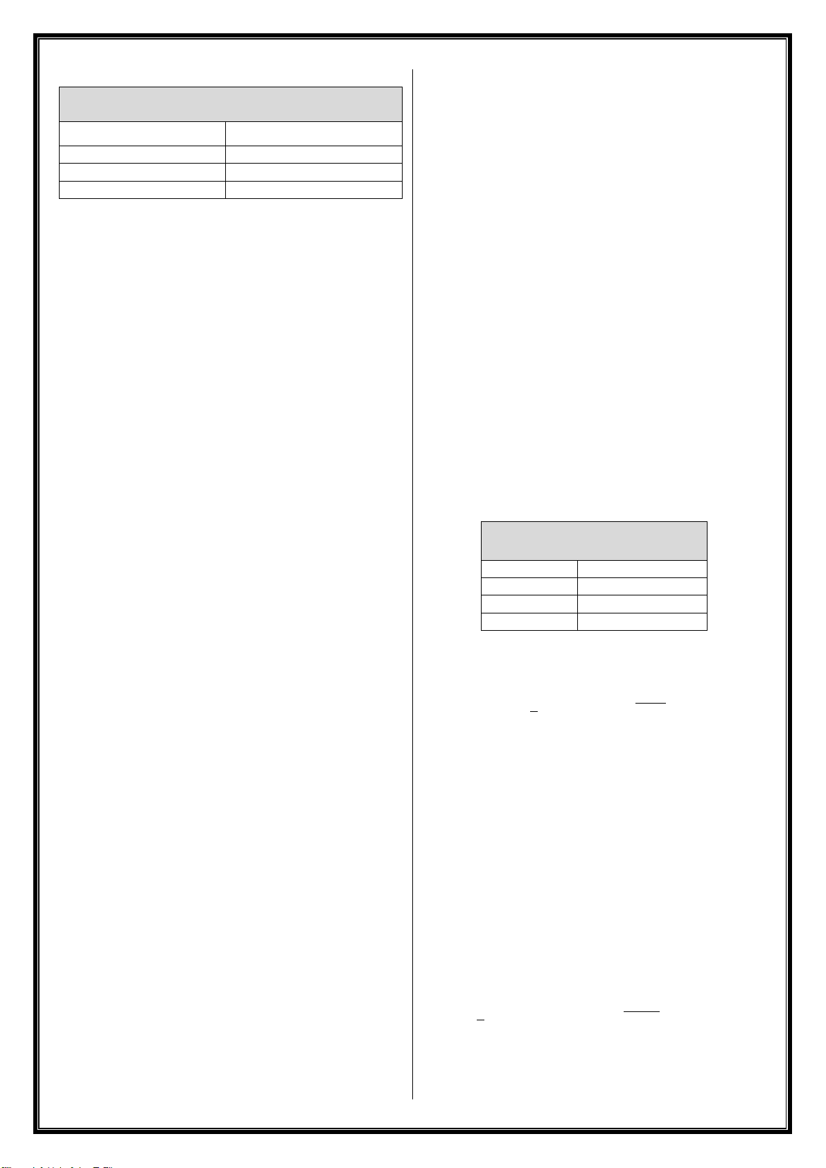
PRODUCT SPECIFICATIONS
Ambient temperature range
-40°C ≤ Ta ≤ +85°C
Maximum Fault Voltage (Um)
250 VDC
250 VAC 50-60 Hz
Frequency Range
≤ 10 GHz
Max RF Power Input (Pi)
7 W (38.4 dBm)
Impedance
50 Ω
Max capacitance
29 pF
IM0032-00
Maximum RF Threshold Power
(table 5 in IEC/EN60079-0)
Equipment Group
Threshold Power
Group I, IIA, III
6 W (37.8 dBm)
Group IIB
3.5 W (35.4 dBm)
Group IIC
2 W (33.0 dBm)
MAXIMUM RF INPUT POWER (Pi)
This value does not consider any cable loss between the RF
transmitter and the M series and may therefore be
considered as the maximum allowable RF transmitter output
power when the M series is directly connected to an RF
transmitter.
Added cable loss between the RF transmitter and the M series
may allow the RF transmitter output power to exceed the
value above as long as the cable loss ensures the power at the
input of the M series is less than or equal to the above values.
It is permissible limited the maximum power output of the
transmitter by a programmable or software setting but it
must not be possible for an end-user to override it.
MAXIMUM PERMITTED
RF THRESHOLD POWER (Pth)
The RF threshold power, sometimes called the effective
isotropic radiated power (EIRP), as defined in IEC/EN60079-0,
is the product of the effective output power of a radio
transmitter multiplied by the power gain of a connected
antenna. The maximum threshold powers for each
equipment group as defined by Table 5 in IEC/EN60079-0 are
provided above.
Because most antennas list the gain relative to an isotropic
radiator (dBi) instead of the raw power gain, it is often easier
to simply add the antenna gain in dBi to the radio output
power in decibel-milliwatts (dBm). Any added cable loss
between the RF transmitter output and the M series input, or
the M series output and the antenna may also be factored in.
▪The resulting threshold power calculated by the above
formula MUST be below the threshold power for the
operating area group rating given above.
▪Consideration of fault conditions in the radio transmitter
is not necessary. The max radio transmitter’s RF power
output should be taken from the manufacturer’s
datasheet in normal operation.
▪A radio output power lower than those provided above
may be used to allow for an antenna with a higher gain.
▪In case of a device with multiple outputs and multiple
antennas, each threshold power is calculated separately
for each output/antenna.
▪Gain of multiband antennas should be evaluated
separately at each frequency.
▪High gain directional antennas on the same device should
not be directed in the same direction.
ANTENNA CONNECTION
The antenna connected to the M series must be installed
following the earthing requirements of IEC/EN 60079-14.
The device must be installed following the earthing
requirements of IEC/EN 60079-14 using the ground
connection available on the device's housing.
MAXIMUM JOULES CALCULATION IN CASE
OF COAX CABLE INSTALLATION
The using of coax cable for installation (radio/M series and M
series/Antenna) needs to be evaluating to ensure that the
maximum energy stored on cable not exceeded the value
allowable per IEC/EN 60079-11 for each channel:
Max energy (Joules) allowed per
IEC/EN 60079-11
Group I
1500 μJ
Group IIA
950 μJ
Group IIB
250 μJ
Group IIC
50 μJ
The calculation can be done according to the following
equation:
Where:
E = Energy
C= M series Capacitance + Coax cable capacitance
(see below M series reference value)
R = Impedance (50Ω)
P = Radio power output
1.5 = Safety Factor
Example
RF Radio Power Output = 2 W
Antenna cable capacitance = 1195 pF
M Series capacitance = 29 pF
Input cable capacitance = 73 pF
Total Capacitance C = 1297 pF
Answer = 0.14 μJ acceptable for any Group
IM0032-00
MAINTENANCE
▪The verification and maintenance of the electrical
equipment must be performed according to IEC/EN
60079-17.
▪The user should guarantee the keeping of the safety
characteristic of the device after maintenance.
▪The maintenance related to the components used for
wiring must be performed according to manufacturer
instruction.
DISPOSAL / RECYCLING
Disposal and recycling of the product according to national
regulation for waste disposal and recycling.
WARNING: Do not dispose of the product and the
components in the environment.
MODEL NOMENCLATURE
M X X 0 X XX XX X XX - XXXXX
1 2 3 4 5 6 7 - 8
1 Number of channel
2 Coupler Series
F RP-SMA Female
N N Female
S SMA Female
T TNC Female
B BNC Female
3 Materials
X various, see sales literature
4 Coaxial Radio Connector
XX various, see sales literature
5 Coaxial Cable Length
00 no cable (direct RF connection)
XX cable length in inches
6 Version (frequency range)
x various, see sales literature
7 Certification Mark
X0 ATEX / IECEx
XN ATEX / IECEx and North America & Canada
standards (dual marking)
xx various, consult Solexy
8 Special execution
XXXXX various, consult Solexy

IM0032-00

IM0034-00
Via Enrico Fermi, 2
I-25015 Desenzano del Garda (BS) - Italy
Phone: +39 030 7870787
Fax: +39 030 7870777
www.solexy.net
M
Intrinsically Safe Antenna Coupler
for use in Hazardous Areas
Installation & Operation Manual
OVERVIEW
The Solexy M series intrinsically safe antenna barrier is a
multichannel protection device that facilitates non-Ex
certified radio antenna installation in hazardous areas. The M
series features a barrier circuit which blocks power voltage in
the event of a radio transmitter/receiver fault. By limiting
transmitted power per local regulations and ensuring the
threshold power requirements for the area of installation are
met, the M series can easily be used with most passive
antennas. The M series protect the radio output signal using
a cable to connect to an antenna that is installed in a
hazardous area.
Note: The information in this manual is intended to assist
with equipment design and ensure proper installation.
READ THIS INSTRUCTION FIRST
To avoid serious or fatal personal injury or major property
damage, read and follow all safety instruction in this manual.
If you require additional assistance, please contact SOLEXY.
SAFETY INSTRUCTION TO HAZARDOUS AREA INSTALLATION
▪The Solexy M series intrinsically safe antenna barrier must
be installed and maintained according to suitable
standards for electrical application in potentially explosive
atmospheres.
▪Installation must be following article 504 of the National
Electrical Code, NFPA70, the Canadian electrical code and
all applicable local codes.
▪Suitably trained personnel shall carry out installation
according to with applicable code practice.
▪Read this first and keep this instruction manual always
available.
▪For proper installation, see the applicable control drawing
DDCD-0013 attached.
MARKING
CUS
ASSOCIATED APPARATUS FOR INSTALLATION IN NON-
HAZARDOUS LOCATION
Class I, Zone 1, AEx [ia Ga] IIA/IIB/IIC
Zone 21, AEx [ia Da] IIIC
Ex [ia Ga] IIA/IIB/IIC
Ex [ia Da] IIIC
Ex [ia Ga] CL I, DIV 1, Group A,B,C,D
Ex [ia Da] CL II, DIV 1, Group E,F,G
This instruction refers to certified equipment covered by the
following certificate:
QPS File: LR1504-3
WARNINGS
1. Solexy M series shall only be installed in a non-hazardous
location (safe area or inside an approved enclosure or p
panel)
2. Solexy M series antenna barrier must be connected to RF
source with a minimum internal impedance of 50Ω.
3. Connected antennas must be assessed, installed and
maintained according to suitable standards for electrical
application in potentially explosive atmospheres and/or
other national standards.
4. Solexy M series antenna coupler does not provide any RF
power limitation. The threshold power must be limited by
the user to achieve the levels defined in the control
drawing DDCD-0013 attached.
5. The user should not repair this equipment.
6. The user should not modify the unit.
7. The unit should not paint from the user.
8. If the equipment is likely to come in to contact with
aggressive substances, it is the responsibility of the user
to take suitable precautions that prevent it from being
adversely affected, thus ensuring that the type of
protection is not compromised. Aggressive substances:
example Acids, liquids, gases with can affected metals.
9. Maximum RF power input shall not exceed the value listed
into product specification paragraph below and control
drawing DDCD-0013.
10. The device can only be supplied by equipment rated for
max overvoltage category II.
11. The device must be installed following the earthing
requirements per local codes using the ground connection
available on the device's housing.
INSTALLATION
For proper installation, see the applicable control drawing
DDCD-0013
1. If the lightning suppressor is used, connect to the output
side of the coupler.
2. Antenna and cable connections should be finger
tightened only. Over tightening can cause permanent
damage resulting in equipment failure.
IM0034-00
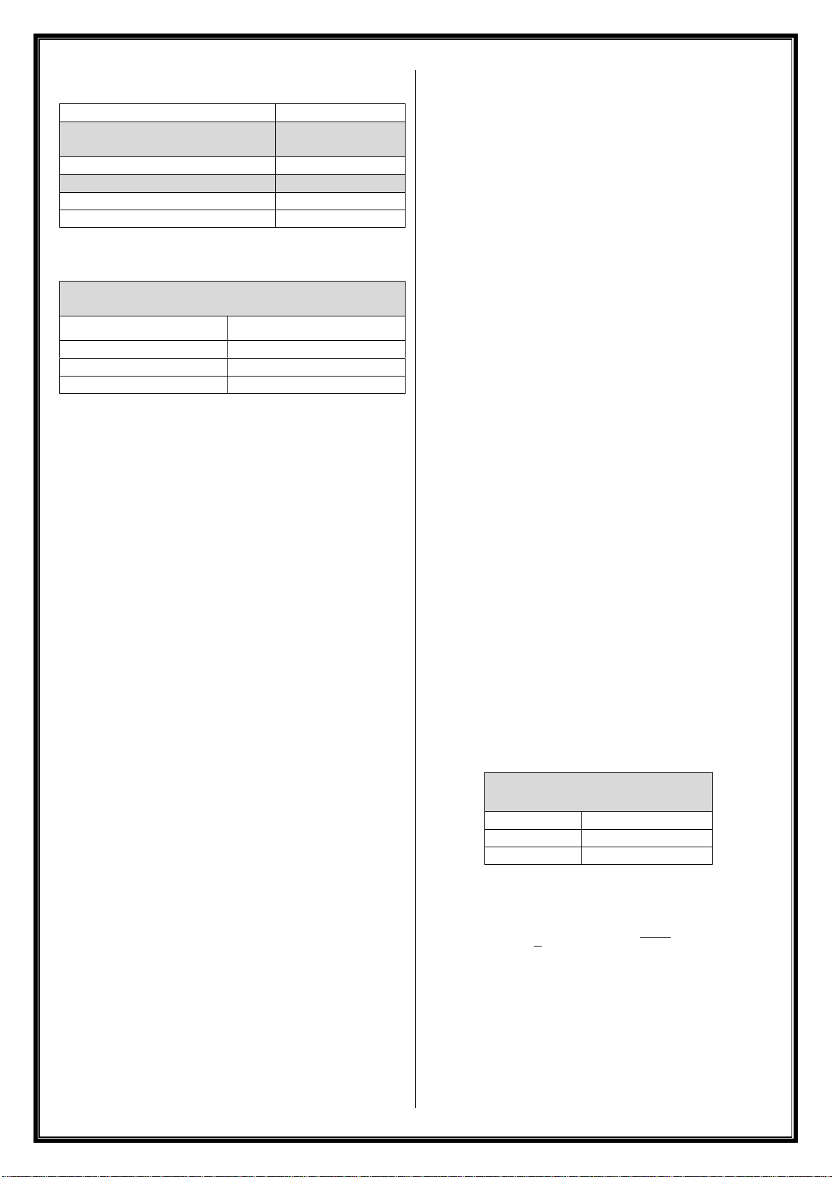
PRODUCT SPECIFICATIONS
Ambient temperature range
-40°C ≤ Ta ≤ +85°C
Maximum Fault Voltage (Um)
250 VDC
250 VAC 50-60 Hz
Frequency Range
≤ 10 GHz
Max RF Power Input (Pi)
7 W (38.4 dBm)
Impedance
50 Ω
Max capacitance
29 pF
Maximum RF Threshold Power
(table 4 in UL60079-0)
Equipment Group
Threshold Power
Group I, IIA, III
6 W (37.8 dBm)
Group IIB
3.5 W (35.4 dBm)
Group IIC
2 W (33.0 dBm)
MAXIMUM RF INPUT POWER (Pi)
This value does not consider any cable loss between the RF
transmitter and the M series and may therefore be
considered as the maximum allowable RF transmitter output
power when the M series is directly connected to an RF
transmitter.
Added cable loss between the RF transmitter and the M series
may allow the RF transmitter output power to exceed the
value above as long as the cable loss ensures the power at the
input of the M series is less than or equal to the above values.
It is permissible limited the maximum power output of the
transmitter by a programmable or software setting but it
must not be possible for an end-user to override it.
MAXIMUM PERMITTED
RF THRESHOLD POWER (Pth)
The RF threshold power, sometimes called the effective
isotropic radiated power (EIRP), as defined in UL60079-0, is
the product of the effective output power of a radio
transmitter multiplied by the power gain of a connected
antenna. The maximum threshold powers for each
equipment group as defined by Table 4 in UL60079-0 are
provided above.
Because most antennas list the gain relative to an isotropic
radiator (dBi) instead of the raw power gain, it is often easier
to simply add the antenna gain in dBi to the radio output
power in decibel-milliwatts (dBm). Any added cable loss
between the RF transmitter output and the M series input, or
the M series output and the antenna may also be factored in.
▪The resulting threshold power calculated by the above
formula MUST be below the threshold power for the
operating area group rating given above.
▪Consideration of fault conditions in the radio transmitter
is not necessary. The max radio transmitter’s RF power
output should be taken from the manufacturer’s
datasheet in normal operation.
▪A radio output power lower than those provided above
may be used to allow for an antenna with a higher gain.
▪In case of a device with multiple outputs and multiple
antennas, each threshold power is calculated separately
for each output/antenna.
▪Gain of multiband antennas should be evaluated
separately at each frequency.
▪High gain directional antennas on the same device should
not be directed in the same direction.
ANTENNA CONNECTION
The antenna connected to the M series must be installed
following the earthing requirements of suitable standards for
electrical application in potentially explosive atmospheres.
Installation must be following article 504 of the National
Electrical Code, NFPA70, the Canadian electrical code and all
applicable local codes.
MAXIMUM JOULES CALCULATION IN CASE
OF COAX CABLE INSTALLATION
In case of coax cable installation (radio/M series and M
series/Antenna) the adding cable needs to be evaluating to
ensure that the maximum energy stored on cable not
exceeded the value allowable per UL 60079-11:
Max energy (Joules) allowed per
UL 60079-11
Group A, B
50 μJ
Group C
250 μJ
Group D, F, G
950 μJ
The calculation can be done according to the following
equation:
Where:
E = Energy
C= M series Capacitance + Coax cable capacitance
(see below M series reference value)
R = Impedance (50Ω)
P = Radio power output
1.5 = Safety Factor

IM0034-00
Example
RF Radio Power Output = 2 W
Antenna cable capacitance = 1195 pF
M Series capacitance = 29 pF
Input cable capacitance = 73 pF
Total Capacitance C = 1297 pF
Answer = 0.14 μJ acceptable for any Group
MAINTENANCE
▪The verification and maintenance of the electrical
equipment must be performed according to suitable
standards for electrical application in potentially explosive
atmospheres and/or other national standards.
▪The user should guarantee the keeping of the safety
characteristic of the device after maintenance.
▪The maintenance related to the components used for
wiring must be performed according to manufacturer
instruction.
DISPOSAL / RECYCLING
Disposal and recycling of the product according to national
regulation for waste disposal and recycling.
WARNING: Do not dispose of the product and the
components in the environment.
MODEL NOMENCLATURE
M X X 0 X XX XX X XX - XXXXX
1 2 3 4 5 6 7 - 8
1 Number of channel
2 Coupler Series
F RP-SMA Female
N N Female
S SMA Female
T TNC Female
B BNC Female
3 Materials
X various, see sales literature
4 Coaxial Radio Connector
XX various, see sales literature
5 Coaxial Cable Length
00 no cable (direct RF connection)
XX cable length in inches
6 Version (frequency range)
x various, see sales literature
7 Certification Mark
N0 North America & Canada standards
XN ATEX / IECEx and North America & Canada
standards (dual marking)
xx various, consult Solexy
8 Special execution
XXXXX various, consult Solexy

Table of contents
Other Solexy Wireless Antenna manuals


Popular Antenna manuals by other brands

weBoost
weBoost 4G-OTR ANTENNA TRUCK EDITION Installation overview

RCA
RCA ANT800 - HDTV Antenna - Outdoor user guide

APM
APM APG-2412CP Specification sheet

KVH Industries
KVH Industries TracPhone V11IP user guide

Maxrad
Maxrad MSO24014PTNF quick start guide

Panasonic
Panasonic Ramsa WX-RP921 operating instructions


