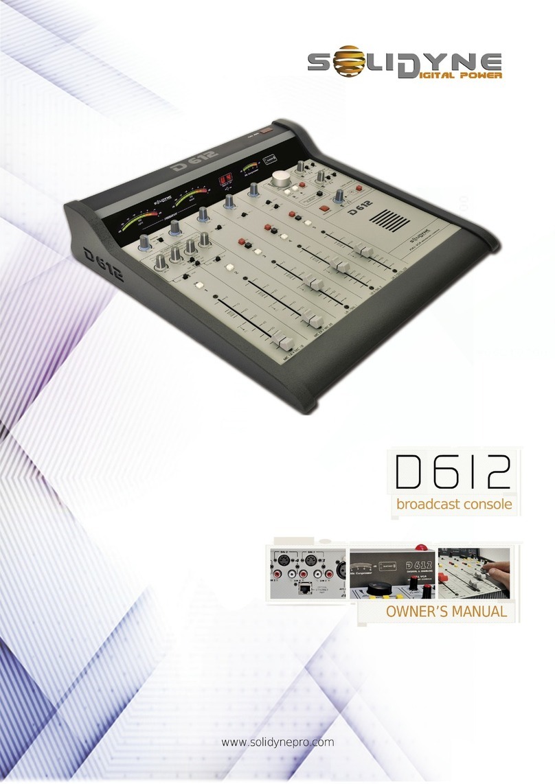
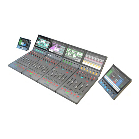
Solid State Logic C10 HD User manual

Solid State Logic
SVISINOO UND
DIGITAL BROADCAST CONSOLE
389'11'9/43'3:'1
Part umber: %
Version 1.0

Begbroke, Oxford, England, OX5 1 U • +44 (0)1865 842300
320 West 46th Street, 2nd Floor, New York, NY 10036, USA • +1 (1) 212 315 1111
3700 Wilshire Blvd, Suite 720, Los Angeles, CA 900310, USA • +1 (1) 323 549 9090
3-55-14 Sendagaya, Shibuya-Ku, Tokyo 151-0051, Japan • +81 (0)3 5474 1144
7 bis, rue de la Victoire, le Blanc Mesnil, Paris 93150, France • +33 (0)1 48 67 84 85
Via Timavo 34, 20124 Milano, Italy • +39 (0)39 2328 094
Visit SSL at U L: http://www.solid-state-logic.com
© Solid State Logic
All ights reserved under International and Pan-American Copyright Conventions
C10 HD, C100 HD, C100 HDS, C200 HD, C300 HD, Blackrock, RIO, NetBridge,
Solid State Logic and SSL are trademarks of Solid State Logic
All other product names and trademarks are the property of their respective owners
No part of this publication may be reproduced in any form or
by any means, whether mechanical or electronic, without the
written permission of Solid State Logic, Oxford, England
Solid State Logic
SVISINOO UND
As research and development is a continual process, Solid State Logic reserves the right
to change the features and specifications described herein without notice or obligation
E&OE

Contents
!!
! !"!
Safety Considerations 3
! !
+7;/)+8;'/1'(1+742
Delivery 2-1
Commissioning 2-1
Training 2-1
Factory Warranty 2-2
.>8/)'1+6:/7+2+398
Console Basics 2-3
Remote I/O Units 2-3
Acoustic Isolation 2-4
Air Conditioning Requirements 2-4
Cable Ducting 2-4
Service Access 2-4
!+).3/)'1+6:/7+2+398
Sync Source 2-5
Mains Input Voltage & Current 2-5
Grounding 2-5
Computer for File Management 2-6
etwork Hubs/Switches 2-6
389'11'9/43'(1/3-
etwork Cables 2-7
Sync Cables 2-7
Analogue Cables 2-7
Digital Cables 2-7
Serial cables 2-7
System Wiring Overview 2-8
Fibre cables 2-9
>89+242543+398
C10 HD Console 2-13
Console Processors 2-15
Console etworks 2-15
Connector panels 2-15
Connectors: 2-17
Alpha-Link Live-R 2-19
Alpha-Link 8-RMP 2-21
MORSE System 2-23
Remote GP IO Interface 2-25
SDI-MADI Interface 2-27
>89+259/438
C10 HD Installation Manual Section 1: Introduction |Page i

Contents
Page ii |Section 1: Introduction C10 HD Installation Manual
! !!
'/38433+)9/43
Chassis Earth 3-3
>3)433+)9/438
+9<470433+)9/438
TCP/IP etwork 3-5
SSL etwork 3-5
+9<47043,/-:7'9/43
User Access to Shared Folders 3-6
Service Access 3-6
‘sbc’ Login (Macintosh OSX) 3-7
‘sbc’ Login (PC) 3-7
‘root’ Login 3-7
Logging Out 3-7
Time Zone Selection 3-8
Server Configuration Options – ‘ssl_setup’ 3-9
15.'/30#
Fibre Cables 3-11
Analogue I/O 3-11
Digital I/O 3-11
8-RMP Remote 3-11
15.'/30
Audio Connection 3-13
Remote Control Link 3-13
Remote ID configuration 3-13
9'-+(4=+8
Fibre Cables 3-15
A43841+'3*+249+4=
Remote GPIO Box 3-17
!'10(')0
8)/11'947
+'*5.43+35:9
+7/'14798A:942'9/434:9+7'9'
!4:).8)7++3#/*+4:95:9
/5
Network Connection 3-25

! "!
3974*:)9/43
/1+!7'38,+7'3*')0:5
IP Address and ames 4-2
Accessing C10 Shared Folders 4-3
System Backup 4-4
Project Backup 4-5
Transfers 4-5
Eyeconix 4-6
Image Specifications 4-6
Updates 4-6
43,/-:7'9/43
Step A1: Check Connections. 4-9
Step A2: Startup Console and Login. 4-9
Step A3: Enter the Routing configuration pages. 4-10
Step A4: Configure MADI connections. 4-11
Alph -Link Configur tion 4-12
Step A5: ame and bundle the IO. 4-13
Grouping multi-ch nnel components: 4-14
Customising IO n mes: 4-15
Step A6: Group the IO 4-16
Step A7: Select signals for the Quick-Routing function. 4-18
Step A8: Assign fixed routing. 4-19
Step A9: Check the new IO configuration. 4-21
Assigning input sources to ch nnels: 4-21
Routing the ch nnel to the Progr mme bus: 4-21
Auditioning the Progr mme bus on the monitors: 4-21
43841+43,/-:7'9/43
Step B1: Set the Boot Project 4-23
Step B2: Set Passwords 4-24
Step B3: Create Projects 4-25
Step B4: Assign Centre Section and Touchscreen Softkeys 4-26
Def ult Project Softkey Assignments: 4-26
The Centre Section Function displ y 4-27
Step B5: Assign Channel Softkeys 4-28
Step B6: Configure Fader Layers 4-29
Step B7: ame Busses, Softkeys and Layers 4-32
N ming Softkey Assignments 4-33
Step B8: Assign Projects to USER MODES Buttons 4-34
Step B9: Upload Eyeconix Images 4-35
Step B10: Further Preset-Level User Configuration. 4-36
Presets 4-36
Control Linking 4-38
Contents
C10 HD Installation Manual Section 1: Introduction |Page iii
! !!
/1++3:
Create 5-3
Inspect 5-3
Edit 5-5
Delete 5-6
Copy 5-7
Text File Operations: 5-9
>89+2+3:
Shutdown 5-11
Sample Rate 5-12
Status 5-13
Clock Settings 5-13
SY C 5-14
4:9++3:
ames 5-17
Groups 5-20
Quickroute 5-23
Ctrl Links 5-24
IO Links 5-25
Alpha-Link Configuration 5-27
DHD Stagebox Configuration 5-28
RIO Setup 5-29
RIO Parameters 5-30
Creating Redundant RIO and MORSE Links 5-35
MORSE Setup 5-36
+9<470+3:
etlist 5-37
IP 5-39
43,/-+3:
Levels 5-41
GPIO 5-42
AFV Setup 5-46
Pan Formats 5-47
+3:
Status DSP 5-49
7439'3+1+3:
Scribble 5-51
Settings 5-51
Ethernet FP Setup 5-52
Fader Reset 5-56
4:9+7'(+125479
Page i |Section 1: Introduction C10 HD Installation Manual
C10 HD Introduction

C10 HD Installation Manual Section 1: Introduction |Page
!
5+)/,/)'9/438 /;
C10 HD Console 6-iv
Alpha-Link 8-RMP 6-1
Alpha-Link Live-R 6-1
RIO 6-2
Console Footprint Drawings 6-3
433+)947+9'/18
DL 96-Pin – Used on the RIO unit An logue I/O c rd 6-8
XLR 3-Pin 6-8
D-Type Multipin 6-8
433+)947/34:98
C10 HD Console 6-9
Headphone Input 6-9
TB Out 6-9
Serial 2 (Ross/Sony) 6-9
Serial 1 (Probel) 6-9
12V Output† 6-10
C10 HD Console 6-10
GPI Outputs 1–12 6-10
GPI Inputs 1–12 6-10
AES/EBU Inputs/Outputs A,B,C (1–8, 9–16, 17–24) 6-11
Analogue Input/Output 1–8 (9–16, 17–24) 6-11
Alpha-Link Live-R 6-11
Microphone Input 6-12
Alpha-Link 8-RMP 6-12
Analogue Output 1–8 6-12
Remote GPIO Box 6-13
GPI Outputs 6-13
GP Inputs 6-13
AES/EBU In/Out 1–8 (9–16, 17–24, 25–32) 6-14
RIO – Analogue and Digital I/O 6-14
Analogue In / Out 6-14
RIO – GP IO 6-15
:*/439+7,')/3-
3;/7432+39'1 5+)/,/)'9/43
!'(1+4:39/3-9.+43841+
+*:3*'3974)+88/3-
!.+
>89+2
:55479+* >3)'9+8
C10 HD Introduction

! # !
3974*:)9/43 ///
Safety Information 7-iii
'*+7'3+1+24;'1
.'33+1439741!/1++24;'1
+397+439741!/1++24;'1
.'33+1!! )7++3+24;'1
+397+!!!4:).8)7++3+24;'1
4<+7 :551>+24;'1
74)+8847+24;'1
425:9+74'7*+24;'1
Page i |Section 1: Introduction C10 HD Installation Manual
C10 HD Introduction

?3974*:)9/43
?',+9>
3,472'9/43
! ! @
… is an overview of the scope of this manual, but, before
installing anything, please take time to read this section
fully as it also includes important information relating to
electrical and to physical safety.
!
!"!

Page iii |Section 1: Introduction C10 HD Installation Manual
C10 HD Introduction
Solid State Logic
SVISINOO UND
Digital Broadcast Console

Introduction
C10 HD Installation Manual Section 1: Introduction |Page 1-1
!"!
Welcome to Solid State Logic’s C10 HD™ broadcast console.
! "
This manual aims to provide everything you are likely to need to know about how to install and configure the C10 HD
console, whether you are a new user with little operational experience, an operator who is familiar with SSL consoles, or
a system administrator who is in charge of the maintenance and configuration of the console.
This manual is divided into seven sections which progressively cover the details required to prepare the proposed location,
be able to install and commission the console and finally configure the software to achieve a basic level of operation – ie.
from delivery to getting audio in and out.
Section 1 3974*:)9/43 –This section. Please take time to read this section fully as it includes important
information relating to electrical and to physical safety.
Section 2 7+5'7'9/43 – Covers the requirements for the intended location of the room/studio and then
lists the peripheral equipment that will be needed. ote that some items and services will need to
be supplied by the facility. This section also provides an overview with more detailed descriptions
of the main component parts of the C10 HD system.
Section 3 389'11'9/43 – Provides step-by-step cabling instructions and includes a section on the initial
setup of the system network.
Section 4 43,/-:7'9/43 – Covers the first steps necessary to set up the console surface in order to
name signals and to make basic I/O routes (This is the section that should result in sound coming
out!)
Section 5 *2/3/897'9/43 – The console can be configured in different ways depending on the degree of
control required by individual users (ie. access levels). This section covers these level settings and
also looks at maintenence and remote monitoring functions.
Section 6 55+3*/)+8 – These include: Specifications, connector pinouts, configuration details and useful
guidelines. Also covered are options that include: Additional I/O, resource sharing capability and
processor redundancy.
Section 7 +7;/)/3-74)+*:7+8– This section shows how to remove the various console assemblies
from the frame.
The information provided by this manual is relevant to the all versions of the C10 HD. In certain areas differences exist
between the 16-channel fader frame and the 24 and 32-channel frames. These details will be highlighted in the specific
section.
!!
Certain configurations of the C10HD console will automatically include commissioning by an SSL engineer so are not
covered, or are only mentioned briefly, in this manual. Some detail of these options is covered in the Appendix section.
These configurations include:
• Consoles fitted with the Redundant processing
• Consoles equipped with a MORSE resource sharing router
• Remote MORSE stageboxes equipped with SDI I/O cards

Page 1-2 |Section 1: Introduction C10 HD Installation Manual
Introduction
& " !""! ! "
Electrical safety hazard.
General safety warning.
Indicates that it is the responsibility of the facility to provide this item or service.
Import nt, useful or otherwise noteworthy inform tion will be indic ted with ruled line bove nd below.
Indicates that additional information may be located on another page or in an Appendix.
!!
For all general enquiries about installation please contact your local SSL representative.
For support or training enquiries contact: Customer Support: [email protected]
!
This manual includes console operational information that will be of use during the console’s initial configuration. More
extensive console operational information will be found in the separate Operator’s Reference Manual.
SSL also provide extensive on-site training for their consoles; if this is of interest, please contact customer support at the
address shown above.
i

C10 HD Installation Manual Section 1: Introduction |Page 1-3
!& !
This section contains definitions and warnings, and practical information to ensure a safe working environment. Please take
time to read this section before undertaking any installation work.
!
‘M inten nce’
All maintenance must be carried out by fully trained personnel. ote: It is advisable to observe suitable ESD
precautions when maintaining electronic assemblies.
‘Non-User Adjustments’
Adjustments or alterations to the equipment may affect the performance such that safety and/or international
compliance standards may no longer be met. Any such adjustments must therefore only be carried out by fully trained
personnel.
‘Users’
This equipment is designed for use solely by engineers and competent operators skilled in the use of professional audio
equipment.
‘Environment’
This product is a class A product intended to form an integrated component part of a professional audio recording,
mixing, TV, radio broadcast or similar studio wherein it will perform to specification providing that it is installed
according to professional practice.
!& ! !
Any mains powered item of SSL equipment that is supplied with a 3-core mains lead (whether connectorised or not) must
always have the earth wire connected to the mains supply ground. This is the safety earth and grounds the exposed metal
parts of the racks and enclosures and must not be removed for any reason.
Safety Information
! !& $
When installing or servicing any item of SSL equipment with power applied, when cover panels are removed,
HAZARDOUS CO DITIO S CA EXIST.
These hazards include: • High voltages
• High energy stored in capacitors
• High currents available from DC power busses
• Hot component surfaces
Any metal jewellery (watches, bracelets, neck-chains and rings) that could inadvertently come into contact with
uninsulated parts should always be removed before reaching inside powered equipment.

"&
To ensure safe operation of this equipment, connect only to an AC power source that contains a protective earthing (PE)
conductor. This equipment is designed for connection to single phase supplies with the neutral conductor at earth potential
– category T or TT – and is fitted with a protective fuse in the live conductor only. This equipment is not designed for
use with live and neutral connections reversed or where the neutral conductor is not at earth potential (IT supplies). This
equipment should not be connected to a power system that switches open the return (neutral) lead when the return lead
also functions as the protective earth (PE).
All mains powered assemblies must be connected to the same mains phase. In particular, note that as PSU redundancy
is standard, the two input leads must OT be connected across different phases of a 3-phase supply.
Mains cables will be coded with either of the following colour schemes:
or
LIVE: Brown Black
EUTRAL: Blue White
EARTH: Yellow/Green Green
The ratings label, which details the console power requirements, is located adjacent to the mains inlet connectors on the
power input panel beneath the rear of the console.
! #"! !!
An external disconnect device is required for this equipment which must be installed according to current wiring
regulations. A detachable power cord, as fitted to this equipment, is a suitable disconnect device.
An external over-current protection device is required to protect the wiring to this equipment which must be installed
according to the current wiring regulations. The fusing or breaking-current is defined in the product specification. In certain
countries this function is supplied by use of a fused plug.
Some units (specifically, those fitted with PSU Redundancy) utilise multiple power sources. This is clearly marked on the
equipment. The finished installation must also be clearly marked to ensure that all sources of power are removed before
servicing work begins.
& !&
The console surface is too heavy for one person to move; ensure sufficient manpower is available when positioning
the console. Take particular care if removing a fully populated RIO chassis from an equipment rack.
If the console trim is removed for any reason then there may be sharp edges exposed on the frame metalwork.
Page 1-4 |Section 1: Introduction C10 HD Installation Manual
Safety Information

C10 HD Installation Manual Section 1: Introduction |Page 1-5
!!
The C10 HD system is CE compliant. ote that cables supplied with SSL equipment may be fitted with ferrite
rings at each end. This is to comply with the current regulations and these ferrites should not be removed.
If any of the console metalwork is modified in any way – particularly the addition of holes for custom switches etc. – this
may the adversely affect the CE certification status of the product.
!!
This equipment has been tested and found to comply with the limits for a Class A digital device, pursuant to part 15 of the
FCC Rules. These limits are designed to provide reasonable protection against harmful interference when the equipment
is operated in a commercial environment.
This equipment generates, uses and can radiate radio frequency energy and, if not installed and used in accordance with
the instruction manual, may cause harmful interference to radio communications. Operation of this equipment in a
residential area is likely to cause harmful interference in which case the user will be required to correct the interference
at his own expense.
!"! $& " ! " "
The symbol shown here, which is on the product or on its packaging, indicates that this product must not
be disposed of with other waste. Instead, it is the user’s responsibility to dispose of their waste equipment
by handing it over to a designated collection point for recycling of waste electrical and electronic
equipment. The separate collection and recycling of your waste equipment at the time of disposal will help
to conserve natural resources and ensure that it is recycled in a manner that protects human health and
the environment. For more information about where you can drop off your waste equipment for recycling,
please contact your local city office, your household waste disposal service or where you purchased the
product.
AA
AA
AA
Safety Information

Page 1-6 |Section 1: Introduction C10 HD Installation Manual
C10 HD Introduction

E $1=A5/1>A-57-.71
=:8$$
E !=19>?-77-?5:9
!4D>5/-7
#1<@5=1819?>
E !=19>?-77-?5:9
%1/495/-7
#1<@5=1819?>
E 9>?-77-?5:9
-.7593
E $D>?18
:8;:919?>
E ;?5:9>
%$ $% F
… will be found a description of services which are
available from SSL that may be useful when planning the
delivery and support of the console. To help with the
preparation, two pre-installation sections then list all the
physical and technical requirements necessary to ensure
with a smooth installation. Finally, each component part
of a C10 HD system is described in more detail.
$%
!#!#%
389'11'9/43'3:'1 +)9/437+5'7'9/43?'-+/

439+398
'-+// ?+)9/437+5'7'9/43 389'11'9/43'3:'1
$% %%$
$1=A5/1>A-57-.71=:8$$
Delivery 2-1
Commissioning 2-1
Training 2-1
Factory Warranty 2-2
Extended Warranty 2-2
!4D>5/-7#1<@5=1819?>
Console Basics 2-3
Remote I/O Units 2-3
Alpha-Link I/O 2-3
Additional I/O 2-3
Acoustic Isolation 2-4
Air Conditioning Requirements 2-4
Cable Ducting 2-4
Service Access 2-4
%1/495/-7#1<@5=1819?>
Sync Source 2-5
Mains Input Voltage & Current 2-5
U S rovision 2-5
rounding 2-5
Computer for File Management 2-6
Computer for MORSE Configuration 2-6
Network Hubs/Switches 2-6
Hub for the TC /I network 2-6
Hub for the SSL network 2-6
Hub for the ipMIDI network 2-6
9>?-77-?5:9-.7593
Network Cables 2-7
Sync Cables 2-7
Analogue Cables 2-7
Digital Cables 2-7
Serial cables 2-7
System Wiring Overview 2-8
Fibre cables 2-9
Fibre Standards 2-9
I/O Fibre Connection Arrangements 2-10
Channel Capacity 2-11

$D>?18:8;:919?>
C10 HD Console 2-13
Frame Layout 2-13
Trim 2-13
Legs 2-13
ower Supplies and Isolator Switches 2-13
Heatsink Clearance 2-13
Console Processors 2-15
Audio rocessor (DS ) 2-15
Single Board Computer (SBC) 2-15
rocessor Redundancy 2-15
Console Networks 2-15
Connector panels 2-15
Connectors 2-17
Alpha-Link LIVE-R 2-19
Fibre Connection 2-19
Connector Summary 2-19
Alpha-Link Live 2-19
Alpha-Link 8-RMP 2-21
Audio and Control Cables 2-21
Connector Summary 2-21
MORSE System (option) 2-23
Remote P IO Interface 2-25
Input Switching 2-25
Output Switching 2-25
SDI–MADI Interface 2-27
Fibre Connections 2-27
$D>?18 ;?5:9>
Loudspeaker Shelf 2-28
Side Arm Trim 2-28
439+398
389'11'9/43'3:'1 +)9/437+5'7'9/43?'-+///

7+5'7'9/43
'-+/; ?+)9/437+5'7'9/43 389'11'9/43'3:'1
1” equals 25.4mm exactly
1metre equals 3’ 3” roughly
1kg equals 2.2lb roughly
Table of contents