Solwise PLV-500AV-PE User manual

500Mbps Powerline
PLV-500AV-PE
User Manual
V1.0

PLV-500AV-PE_User Manual
i
Contents
1Introduction ........................................................................................................ 1
1.1 Product Features ................................................................................... 1
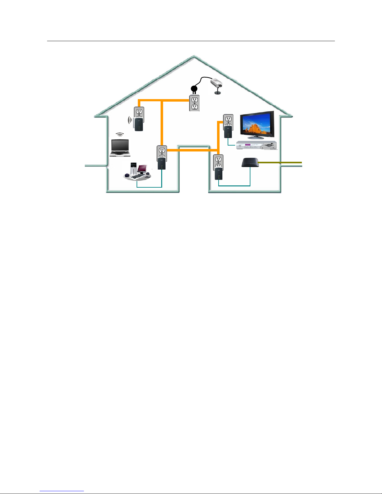
1.2 Application............................................................................................. 1
1.3 System Requirements ........................................................................... 2
1.4 Packing List ........................................................................................... 2
2Safety Precautions ............................................................................................. 3
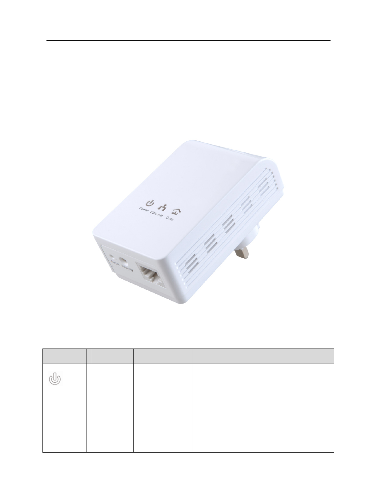
3Getting to Know the Adapter .............................................................................. 4
3.1 The Ethernet Interface........................................................................... 4
3.2 The Adapter's Buttons ........................................................................... 4
3.3 The Adapter's LEDs............................................................................... 5
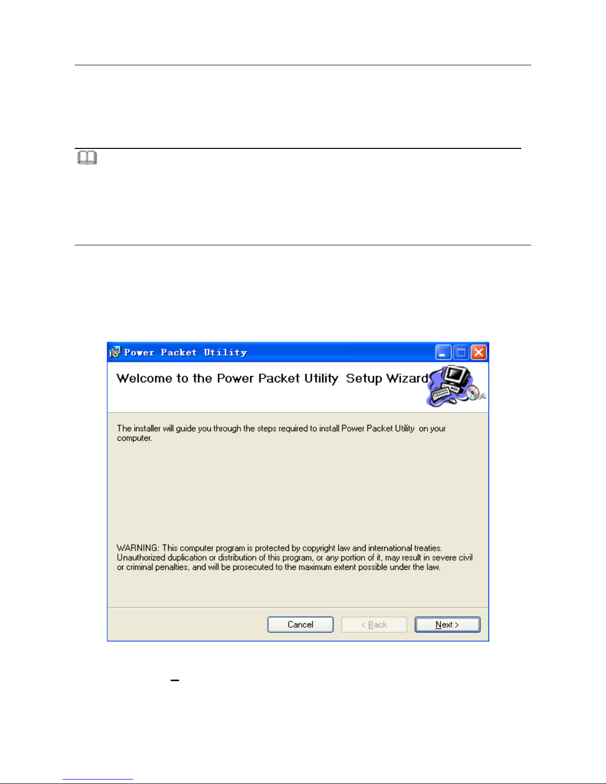
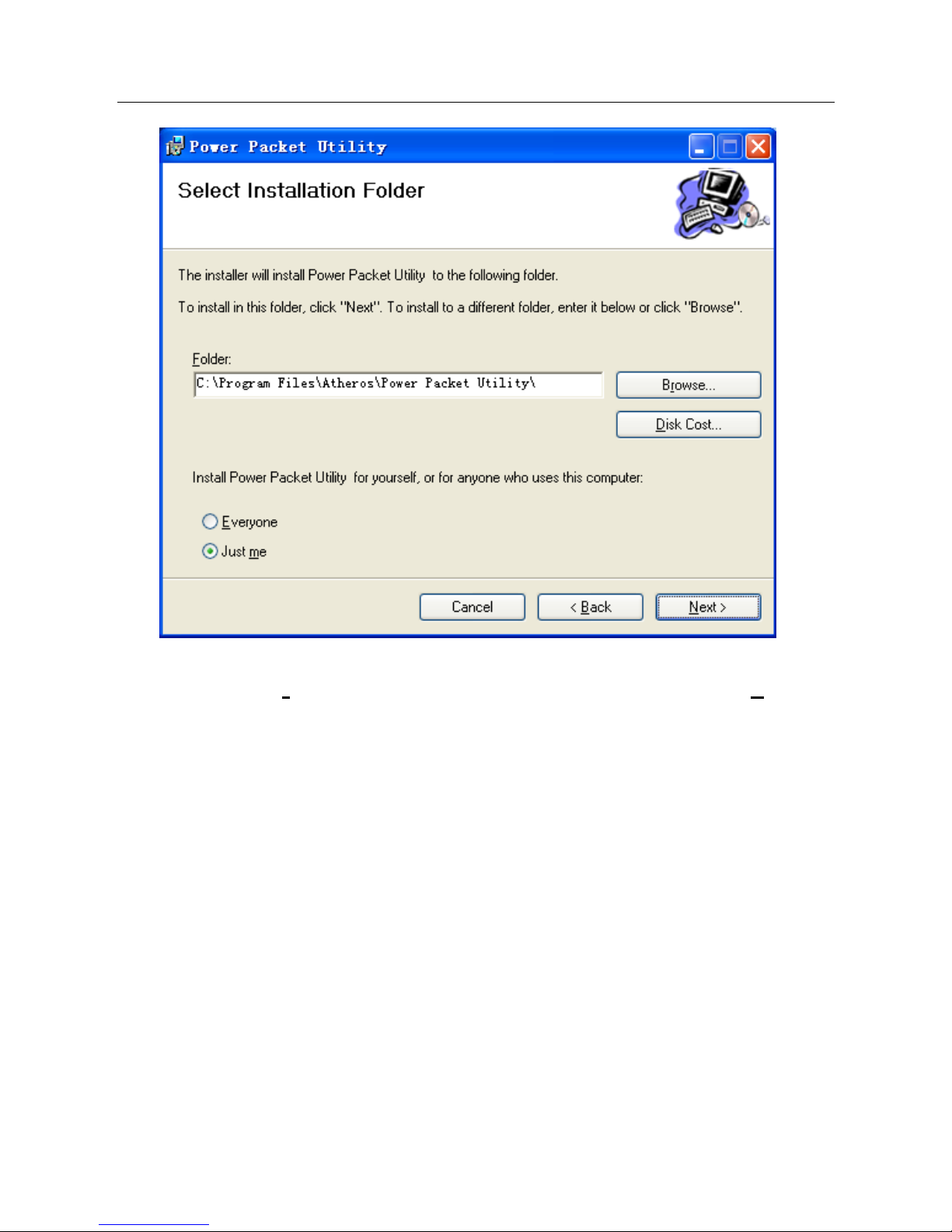
4How to Install the Utility...................................................................................... 7
5How to Use the Utility....................................................................................... 10
5.1 Main Tab .............................................................................................. 10
5.2 Privacy Tab .......................................................................................... 13
5.3 Diagnostics Tab ................................................................................... 16
5.4 About Tab ............................................................................................ 18
6How to Use the Security Pushbutton ............................................................... 19
6.1 Forming a HomePlug AV logical network ............................................ 19
6.2 Joining a Network................................................................................ 20
6.3 Leaving a Network............................................................................... 21
7How to Improve the Transmission Capacity..................................................... 23
Appendix A Specifications ................................................................................. 24
Appendix B Acronyms and Abbreviations ......................................................... 26
Appendix C About QoS...................................................................................... 28

PLV-500AV-PE_User Manual
1
1 Introduction
The PLV-500AV-PE is a mini-PLC adapter. It can transmit data up to 500Mbps in the
household powerline. It can be connected to the power socket directly without new
wire. The PLV-500AV-PE adapter can enter power save mode triggered by multiple
conditions. It can help you to establish a high-speed network that supports video,
voice and data without wiring and drilling. It is suitable for using in a wide range of
both residential (at home) and commercial (offices, apartments, hotels, warehouses)
network applications.
1.1 Product Features
Without new wiring, every power socket becomes a connection node in
the household.
Plug-and-play to your routers, computers and other network devices.
Provides power save mode. In the power save mode, the output
consumption of the device is less than 1W.
The physical data rate is up to 500Mbps.
1.2 Application
zHigh Definition (HD) and Standard Definition (SD) video distribution
zHigher data rate broadband sharing for powerline LAN
zShared broadband internet access
zTV over IP (IPTV) and Voice over Internet Protocol (VoIP)

PLV-500AV-PE_User Manual
2
ADSL
FTTH
WiFi Extender
PLC Camera
Powerline
PLC
PLC
PLC
ADSL
FTTH
WiFi Extender
PLC Camera
Powerline
PLC
PLC
PLC
Figure 1 PLC network architecture
1.3 System Requirements
Operating system: Windows 98SE, 2000, ME, XP 32/64 bit and Vista
32/64bit
CPU: Intel Pentium III or better, clock rate faster than 2.0GHz
recommended
RAM: At least 128MB
Screen resolution: Any resolution
Free disk space: At least 20MB
Network interface: At least one Fast Ethernet (100 Mbps) network card,
and a Ethernet Cord
1.4 Packing List
PLV-500AV-PE x 1
CD ROM x 1
RJ45 Ethernet cable x 1

PLV-500AV-PE_User Manual
3
2 Safety Precautions
This device is intended for connection to the AC powerline. For installation
instructions, please refer to the installation section of this guide. The following
precautions should be taken when using this product.
Read all instructions before installing and operating this product.
Follow all warnings and instructions marked on the product.
Unplug the device from the wall outlet before cleaning. Use a damp cloth
for cleaning. Do not use liquid cleaners or aerosol cleaners.
Do not operate this product near water.
This product should never be placed near or over a radiator or heat
register.
Do not use an extension cord between the device and the AC power
source.
Only a qualified technician should service this product. Opening or
removing covers may result in exposure to dangerous voltage points or
other risks.
Do not plug the device into a power strip or surge protector because
these devices may consist of filter and impair signal.
Avoid plugging the device right next to noisy sources such as cell phone
charger, Halogen light, noisy desktop computer, vacuum cleaner, etc.
These cases result in poor transmission speed.
Unplug the device from the wall outlet and refer the product to qualified
service personnel for the following conditions:
- If liquid has been spilled into the product
- If the product has been exposed to rain or water
- If the product does not operate normally when the operating instructions
are followed
- If the product exhibits a distinct change in performance

PLV-500AV-PE_User Manual
4
3 Getting to Know the Adapter
3.1 The Ethernet Interface
Ethernet: The Ethernet port connects to an Ethernet network cable. The other end of
the cable connects to your computer or other Ethernet-enabled network device.
3.2 The Adapter's Buttons
The following figure shows the adapter’s buttons.
Figure 1 Side panel of the device
Reset: Restore the factory default settings.
Security: (also referred to as the NMK button):Set the status of the device
members.
Pressing and holding the Security button for more than 10 seconds
randomizes the NMK value.

PLV-500AV-PE_User Manual
5
Pressing and holding the Security button for less than 3 seconds makes the
adapter a member of the existing AVLN. For more details, see chapter 6 .
3.3 The Adapter's LEDs
All adapter's LEDs are located on the front panel. There are 3 LEDs to indicate the
adapter’s status.
Figure 2 Top view
The following table describes the LEDs on the device.
LED Color Behavior Description
Green On System runs normally.
(Power)
Green Blink System enters the power save
mode.
System is resetting.
System is in the process of
password synchronization.

PLV-500AV-PE_User Manual
6
LED Color Behavior Description
- Off The PLC adapter is powered off.
Green On Ethernet connection has established.
Green Blink Data is being transmitted.
(Ethernet) - Off No Ethernet connection.
Green/Red On The PLC adapter has connected to the
powerline network. The Data LED color
will vary according to the physical rate.
PHY RATE>80Mbps: green
40<PHY RATE<80Mbps: orange
PHY RATE<40Mbps: red
(Data)
-Off The PLC adapter does not connect to
the powerline network.
Note:
The Power, Ethernet and Data indicators blink quickly when the device is powered
on. At that moment, the Power and Ethernet indicators are green, and the Data
indicator is orange.
When data is being transmitted, the Data indicator keeps on but does not blink.

PLV-500AV-PE_User Manual
7
4 How to Install the Utility
Note:
Before installing the PLC utility software, make sure that there is no any other
powerline utility installed on your computer. If there is another utility installed, please
uninstall it and restart your computer.
Follow the steps below to install the utility. No password or CD-Key is needed.
Step 1 Please insert the utility CD into the computer’s CD-ROM drive. Select the
PLC 500AV Utility Installation folder and then double-click the
setup.exe. A page for installing the utility software appears.
Figure 3 Opening the setup wizard
Step 2 Click Next > to show the following page.

PLV-500AV-PE_User Manual
8
Figure 4 Selecting the folder
Step 3 Click Browse… to select the installation folder, and then click Next > to
continue.

PLV-500AV-PE_User Manual
9
Figure 5 Completing the installation
Step 4 Click Close to finish the installation.

PLV-500AV-PE_User Manual
10
5 How to Use the Utility
5.1 Main Tab
The Main screen provides a list of all powerline devices logically connected to the
computer when the utility is running.
The top panel shows the local HomePlug devices connected to the network
interface card (NIC) of the computer. Click Connect. The utility automatically scans
the powerline periodically for other HomePlug devices when it is connected to the
local device. If no local HomePlug device is discovered, the status bar displays NO
HOMEPLUG ADAPTERS DETECTED.
Figure 6 Main tab
The lower panel displays all the HomePlug remote devices, which are discovered
in the current logical network. The total number of remote devices connected in the
same network is displayed above the remote device panel. Network type (Public

PLV-500AV-PE_User Manual
11
or Private) depends on the network status of the local device. Autoscan shows
whether the autoscan function is on. The following information is displayed for all
the devices that appear in the lower panel.
Device Name
This column shows the default device name, which may be modified. To change the
name, click Rename,or click the name and edit it in the list.
MAC Address
This column shows the MAC addresses of the remote devices.
Password
By default, this column is blank. You can click Enter Password to change it. The
steps for setting the password of the device (required when creating a private
network) are as follows:
Step1 Click the device name to select the device in the lower panel.
Step2 Click Enter Password. A dialog box appears, showing the device name
and password. See Figure 7.

PLV-500AV-PE_User Manual
12
Figure 7 Setting the device password
Step3 Click OK to verify the password. The password field accepts the device
password in any case formats, with or without dash.
A confirmation box appears if the password is entered correctly. If a device is not
found, a message appears, providing suggestions to solve the common problems.
This process might take a few seconds to get completed.
Add
This button is used to add a remote device to the existing network by entering the
device password of the device. A dialog box appears. See Figure 8. You can enter
a device name and the password.
If the device is found and the password is entered correctly, a confirmation box
appears. If a device is not found, a message appears, providing suggestions to
solve the common problems.

PLV-500AV-PE_User Manual
13
Figure 8 Adding the remote device
Note:
The device must be in the powerline (plugged in), so that you can confirm the
password and add the device to the network. If the device is not located, a warning
message appears.
Scan
This button is used to perform an immediate search for HomePlug devices
connected to the powerline network. By default, the utility automatically scans every
a few seconds and updates the displayed information.
5.2 Privacy Tab
In the Privacy screen, you can maintain security for the logical network and select
the device included in the network. See Figure 9.

PLV-500AV-PE_User Manual
14
Figure 9 Privacy tab
All HomePlug devices are loaded using a default logical network (network name),
which is normally “HomePlugAV”. In the Privacy screen, you can modify a private
network by changing the network names and the passwords of the devices.
You can always reset to the HomePlug network (Public) by entering “HomePlugAV”
as the network name or by clicking on the Use Default button.
Note:
If the network name changes to anything other than HomePlug, the network type in
the main screen is displayed as Private.
Set Local Device Only
This button is used to change the network name and password of the local device.
If a new network password is entered, all the devices appeared in the main panel
prior to this are no longer present in the new network, effectively making the local
devices not to communicate to the devices which are in the old logical network.

PLV-500AV-PE_User Manual
15
Click Set Local Device Only, the devices previously set up with the same logical
network (same network name) appears in the device list.
Set All Devices
This button is used to change the logical network of all devices that appear in the
main panel. If these devices whose passwords have been entered for the same
logical network, a dialog box appears, indicating the success of this operation. For
the devices whose passwords are not entered, this operation will fail and it will
report a failure message.

PLV-500AV-PE_User Manual
16
5.3 Diagnostics Tab
The Diagnostics screen shows the system information and history of all remote
devices appeared over a period of time. See Figure 10.
The Upper panel shows technical data concerning software and hardware on the
host computer that are used to communicate through HomePlug on the powerline
network. It includes the following:
Operating system platform/version
Host network name
User name
MAC address of all NICs (Network interface card) connected to the host
Identify versions of all driver DLLs and libraries used (NDIS) and
optionally
HomePlug chipset manufacturer name (Turbo Only devices)
MAC firmware version (Turbo Only devices)
MAC addresses of all devices connected locally to the host
Version of the configuration utility
Vendor name

PLV-500AV-PE_User Manual
17
Figure 10 Diagnostics tab
The Lower panel displays the history of all remote devices appeared on the
computer over a certain period of time. All the devices and the parameters of the
devices on the powerline network are listed. Devices that are active on the current
logical network show a transfer rate in the rate column. Devices on other networks,
or devices that no longer exist are shown with a “?” in the rate column. The
following remote device information is available from the diagnostics screen:
Device alias name
MAC address
Password
Device last known rate
Device last known network name
HomePlug chipset manufacturer name
Date device last seen on the network
MAC firmware version

PLV-500AV-PE_User Manual
18
The diagnostics information displayed can be saved to a text file for later use, or be
printed for reference for a technical support call. Click Delete to delete the devices
which are no longer part of the network. A dialog window pops up with a
confirmation message if the user wants to delete a device whose password has
been entered.
5.4 About Tab
The About screen shows the software version and provides a html link to a website,
such as www.PowerPacket.com. Clicking the web address, you can visit the web
site.
Figure 11 About Tab
Preferences
The lower part of the panel displays options for turning the autoscan function on or
off.
Table of contents
Other Solwise Adapter manuals