SOMFY DIGITAL ELECTRICITY 9026105 Quick reference guide

DEPLOYMENT GUIDE
SOMFY DIGITAL ELECTRICITY™

TABLE OF CONTENTS
I. OVERVIEW
DESCRIPTION
CONNECTIONS & LEDs
II. INSTALLATION
MOUNTING & POWER
WIRING TO SYSTEM FOR OPERATION
III. SOFTWARE SET UP
INSTALL
CONNECT
IV. SOFTWARE FEATURES
STATUS
HISTORY
EVENTS
POLICY
V. SOFTWARE SETTINGS
NETWORK
NETWORK TIME PROTOCOL (NTP)
ACCOUNT
USERS
ALERTS
WEBHOOKS
SIMPLE MAIL TRANSFER PROTOCOL (SMTP)
SIMPLE NETWORK MANAGEMENT PROTOCOL (SNMP)
SECURE SHELL (SSH) SERVER
SOFTWARE UPDATE
FIRMWARE UPDATE
DIAGNOSTICS
FACTORY RESET & REBOOT
VI. APPENDIX
USER ROLE CAPABILITIES MATRIX
3
4
5
7
9
14
2of 15
SOMFY DIGITAL ELECTRICITY™
DEPLOYMENT GUIDE
VERSION 20.04 | APRIL 2020 | Prepared by PROJECT SERVICES

Digital Electricity™ is a Limited Power Source which allows to utilize standard 18AWG 2-Conductor Cable without
conduit while confirming to the National Electric Code standards for building installations. When the Transmitter and
Digital Electricity™ Power Panel for SDN with Receiver are pair together the Digital Electricity™ system is formed.
A fully loaded Transmitter provides 8 channels of Digital Electricity™ up to 600W per channel, total 3000W per unit.
Each of the 8 connected Receivers will provide up to 3A at a nominal output voltage of 336V DC per unit.
The Digital Electricity™ Transmitter and Receiver are listed products certified to safety and EMC standards by
Nationally Recognized Test Laboratories (NRTLs). If a person or foreign conductor comes in contact with the wiring,
power is disconnected, preventing fire, equipment damage and personal injury.
I. OVERVIEW
CONNECTIONS
LEDs
3of 15
DE Outputs
LED
NORMAL STATES LED PATTERN NOTE
Normal Operation Normal operation
Boot-Up Start-up sequence occurs when power is first applied to the receiver
Pre-Charge DE Part of normal set-up sequence
Pre-Charge Load Part of normal set-up sequence
FAULTS LED PATTERN FAULT CODE TROUBLESHOOTING
Load Connection 2 Blinks Connection problem between Receiver Output and load
Check Receiver Output polarity; Check connections to load
Overload 3 Blinks Load Current too high
Reduce load; Check wiring
Transmitter 4 Blinks Transmitter power issue
Check Transmitter card(s); Check wiring from Transmitter
Temperature 5 Blinks Receiver over temperature
Reduce ambient temp. surrounding Receiver; Reduce load
Short Circuit 6 Blinks Short circuit detected between Receiver and load
Check wiring; Check load for short circuit or ground fault
Internal Failure 8 Blinks Internal hardware failure
Contact Voltserver
*included with Digital Electricity™ Power Panel for SDN #1870628
LEDs
Management Port Power Input
Power Output
Digital Electricity™
Transmitter
Digital Electricity™
Receiver

1. Connect a Phoenix Contact Output Connector and 18AWG (minimum) 2-Conductor Cable from an open Output
Port on the Transmitter to the open end of the Splice Connector in the DE Power Panel (see Wire Detail below):
•Max Distance is 1000' using 18AWG 2-Conductor Cable (Contact Somfy Representative for additional distance requirements)
•The minimum wire gauge for use with Transmitters is 18AWG copper conductors; Mutual conductor capacitance max 15-40pF/ft (49-164pF/m)
•The voltage rating of the transmission wiring between Transmitter and Receiver(s) must be 300Vrms
•Consider the requirements of plenum vs. riser cabling
Digital Electricity™ Transmitter #9026105
•Can be mounted on a standard 19” network rack
•Receives power by a Dedicated AC Outlet
II. INSTALLATION
MOUNTING & POWER
4of 15
WIRING TO SYSTEM FOR OPERATION
Digital Electricity™ Power Panel for SDN #1870628
•Mount on-wall or in-wall between studs
•Receives power by the Digital Electricity Transmitter

Download the latest VoltServer ETX8 Discovery Tool software.
Software can be downloaded from: https://www.somfypro.com/services-support/software
•When possible, install as administrator
Access the GUI using one of the following supported browsers:
•Mozilla Firefox v52 or later
•Google Chrome v56 or later
•Microsoft Edge
5of 15
III. SOFTWARE SET UP
INSTALL
1. Using a standard CAT-5e or higher cable, connect your laptop to the ENET Port on the Digital Electricity
Transmitter by one of the following 4 methods pictured below:
CONNECT
DHCP ROUTER WITH WIRED ETHERNET
Ethernet Router with DHCP To laptop connected
via wired Ethernet
Digital Electricity™ Transmitter
DHCP ROUTER WITH WIFI
Ethernet Router with DHCP
Laptop connected
via Wifi
Digital Electricity™ Transmitter
AUTO IP CONNECTION VIA CROSSOVER ETHERNET
Ethernet crossover connection: autoIP
To laptop
Digital Electricity™ Transmitter
AUTO IP CONNECTION VIA UNMANAGED SWITCH
Switch without DHCP: autoIP To laptop
Digital Electricity™ Transmitter

6of 15
ADDRESSING
2. Launch the Discovery Tool and then click Discover. This will search the entire network that you are connected to
and display all of the Transmitters that it finds.
3. The discovery tool will list all of the Transmitters information on the screen.
4. Click the Connect button for the Transmitter that you want to connect to.
5. This will open a browser window with a login screen. Login info can be found on the side of the Transmitter.

All “real time” device telemetry is displayed on the main Status page:
•Device (Transmitter) Name
•Total System Power
•System Faults
•Device (Transmitter) Serial, MAC and IP Addresses
•Channel Numbers and editable Channel Names
•Channel Power, Status, Faults
•Channel Analog Setpoint (lighting applications only)
7of 15
IV. SOFTWARE FEATURES
STATUS
Monitor the total power (watts) output of
the transmitter in real time under the
System Power section on the Status page
Transmitter information can
be found under the
Info
section on the Status page
Customize Channel Names:
1. Select a Channel from the main Status page
2. Click on the current Channel name and it will turn into a text box
3. Type the new name and click the green check mark to save
Power for each Channel can
be turned off or on with the
Output toggle button. It is
recommended to turn power
off for unused channels.

8of 15
ADDRESSING
HISTORY
The History tab will allow you to view the history log of each channel.
Select the date range to narrow the search and use the “Export CSV” button to export the data to a file.
EVENTS
The Events tab will allow you to find a log of all events on all channels.
Select the date range to narrow the search and use the “Export CSV” button to export the data to a file
POLICY
The Policy tab will allow you to Enable and Disable the Dry Contact Input Policies and configure the actions. The
Transmitter features a dry contact input enabling the user’s system to trigger the policy software to enable features
such as load shedding for battery back-up. The dry contact input should be connected to either an open circuit or
closed circuit. Do not apply voltage to the dry contact. For details on this functionality contact Somfy Support.

The Network page will allow you to set/change the network name of the
Transmitter, set/change a Static IP, or make the Transmitter DHCP.
9of 15
V. SOFTWARE SETTINGS
The gear icon will take
you to the Settings page.
The NTP page will allow you to set the Transmitter to synchronize it’s internal
clock to the NTP server of your choice, and set a time zone. Enter the server
URL and connect the Transmitter to a network with internet access.
NETWORK TIME PROTOCOL (NTP)
ACCOUNT
The Account page will allow you to change the account email address, roll and password.
NETWORK
Settings
Menu
10 of 15
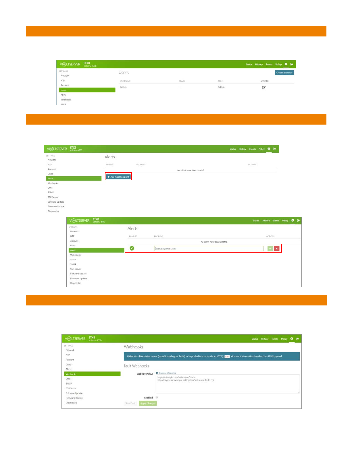
USERS
The Users page will allow you to set up different User accounts for the Transmitter. Users can be set up as
one of 3 roles: Admin, Operator or Basic. See the chart in the appendix for the rights of each role.
ALERTS
The Alerts page will allow you to set up email addresses to be notified when there is an alert. Click on the “Add Alert
Recipient” button, enter the email address and click the green checkmark. To delete the recipient just click the red X.
WEBHOOKS
The Webhooks page will allow you to set up information to be automatically sent to another server via HTTP with a
JSON payload. Create, edit or remove commands in the boxes provided. Apply changes and send a test with the
buttons on screen.

11 of 15
ADDRESSING
SIMPLE MAIL TRANSFER PROTOCOL (SMTP)
The SMTP page will allow you to set up, change or remove SMTP Server settings for outgoing mail communication
over the network. Refer to the project’s network administrator for server information to be populated here.
SIMPLE NETWORK MANAGEMENT PROTOCOL (SNMP)
The SNMP page will allow you to set up, change or remove SNMP information email communication.
Refer to the project’s network administrator for server information to be populated here.
SECURE SHELL (SSH) SERVER
The SSH Server page will allow you to Enable or Disable the use of an SSH server and to add Authorization Keys.
Refer to the project’s network administrator for server information to be populated here.

12 of 15
ADDRESSING
SOFTWARE UPDATE
The Software Update page will allow you to update the Transmitter’s Software.
Select the update file and click the “Update” button. A progress bar will show you
the % that the update is at, and it will prompt you when completed.
FIRMWARE UPDATE
The Firmware Update page will show you the current version Firmware on the Transmitter and allow
you to update the firmware via the web interface. A progress bar will show you the % that it is at and
will prompt you when completed.
DIAGNOSTICS
The Diagnostics page will allow you to turn On/Off Error Reporting.
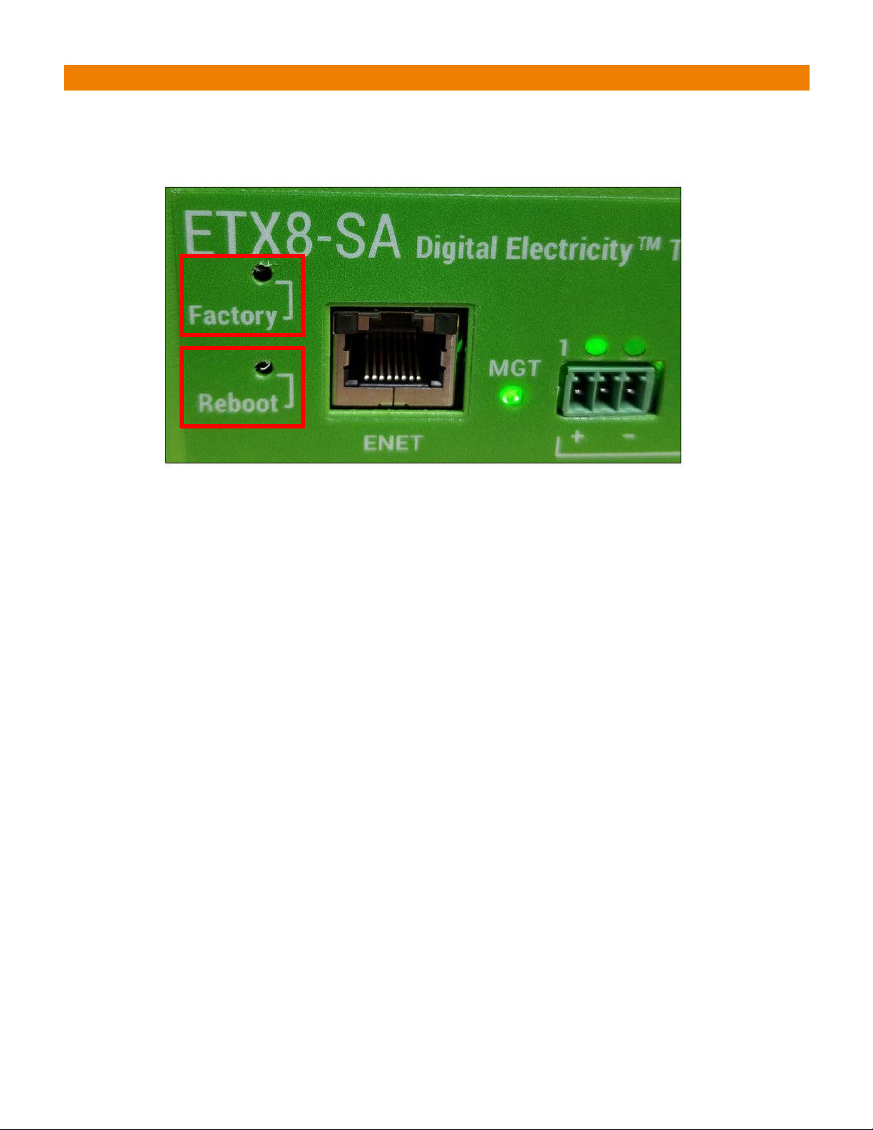
There are 2 recessed buttons on the front of the Transmitter that are used to Clear/Reset the
Transmitter to it’s factory settings, and to Reboot the Transmitter. Press the recessed button once to
trigger the action.
FACTORY RESET & REBOOT
13 of 15

14 of 15
VI. APPENDIX
USER ROLE CAPABILITIES MATRIX

15 of 15
DOCUMENT PREPARED BY SOMFY NORTH AMERICA PROJECT SERVICES
Version 20.04
April 2020
FOR QUESTIONS OR ASSISTANCE PLEASE CONTACT TECHNICAL SUPPORT:
(800) 22-SOMFY (76639)
technicalsupport_us@somfy.com
SOMFY SYSTEMS INC
SOMFY NORTH AMERICA HEADQUARTERS
121 Herrod Blvd.
Dayton, NJ 08810
FLORIDA
1200 SW 35th Ave.
Boynton Beach, FL 33426
CALIFORNIA
15301 Barranca Pkwy.
Irvine, CA 92618-2201
CANADA
5178 Everest Dr.
Mississauga, Ontario L4W2R4
www.somfysystems.com
This manual suits for next models
1
Table of contents
Popular Portable Generator manuals by other brands

Suin
Suin TFG2900A Series user guide

Briggs & Stratton
Briggs & Stratton 40276 Illustrated parts list

Ozone Solutions
Ozone Solutions DR-10 Installation & operation manual

Autopilot
Autopilot CoPilot Ozonator 3 Installation & operation manual

Champion Global Power Equipment
Champion Global Power Equipment 201004 quick start guide

Jackery
Jackery JSG-0304B user manual


